
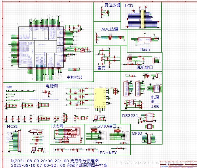
The circuit I drew for the board was based on a lot of schematic diagrams. Here are the links:
https://oshwhub.com/24C02/quan-zhiv3s
https://yuanze.wang/posts/v3s-dev-board-hardware/
There are other things that are difficult to post.
The basic reference for packaging is the first one, which is also the open source project of Lichuang (thank you very much)
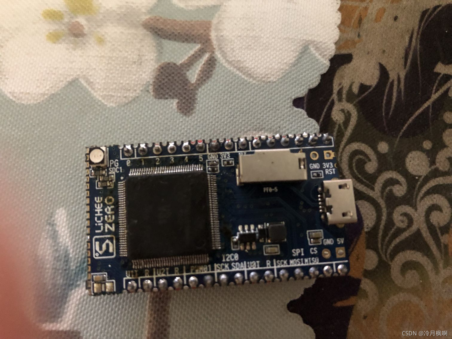
Two days ago, I was going to transplant Linux on the Lychee Pi motherboard I purchased. It took me a while to transplant uboot, zImage, and the root file system, and finally it started successfully.
Because mine is the smallest system board and does not have an Ethernet interface, it is very difficult to develop every time (you need to remove the SD card and then burn the program and start it). This step is very cumbersome.
In view of the above reasons, I plan to connect an Ethernet interface, download the device tree and zImage through the TFTP protocol, and share the root file system through NFS.
Because the V3S chip has EPHY inside, there is no need for an external Ethernet chip. It only needs an Ethernet interface. So, I found an Ethernet port and connected it according to the line sequence corresponding to the schematic diagram.
After constant testing, it finally failed to work (uboot has set up the Ethernet driver and loaded it successfully). After constant welding and testing (a whole afternoon of work), it finally failed to drive.
Given that there is no ability to drive the network. I think the Ethernet interface may be broken, and I don’t have any more. It will take time to buy one, so I might as well draw a board myself and get familiar with the hardware.
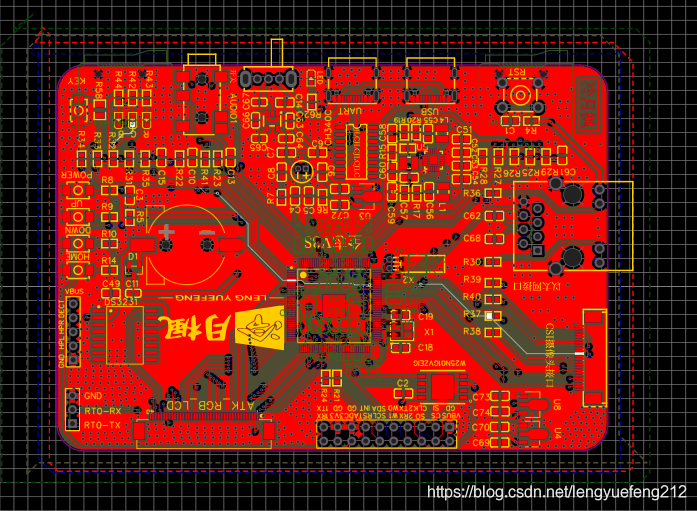
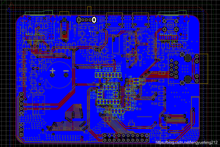
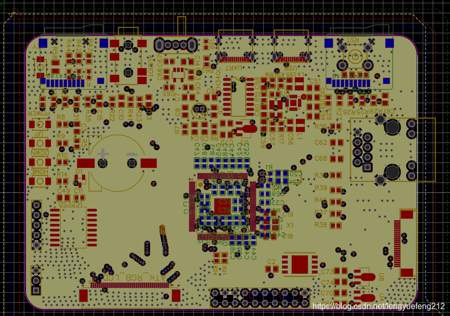
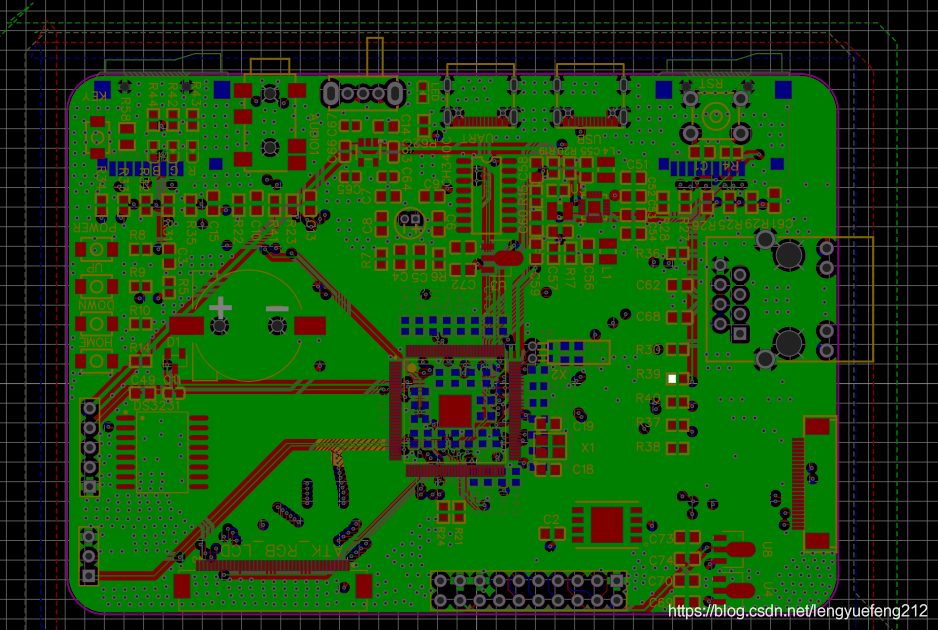
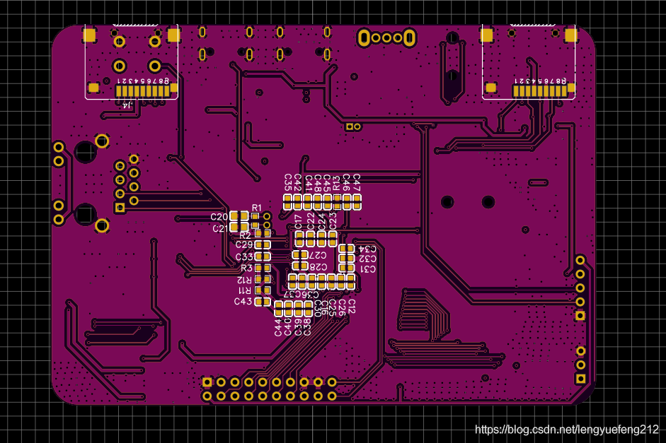
This time I painted a 4-layer board. It was also my first time to paint a 4-layer board.
The drawing board process is long. After two or three days of continuous drawing, I finally completed the final design just now.
Here is the record of the drawing board: It’s really a lot of hard work
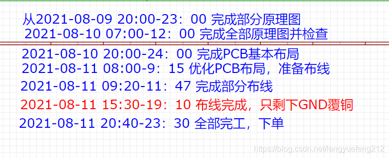
It can be seen that this process is long, and it really makes me exhausted.


I will briefly record it here. After all, it is getting late now and it’s time to go to bed.
Subsequent welding debugging (pit filling)
Previously, I drew a V3S development board and placed an order. Because I drew a 4-layer board, the production progress was relatively slow. I waited for about 6 or 7 days before I received the shipment from Jialichuang. The board was sent (maybe also because of the epidemic). But I didn't solder at this time. Because of the epidemic, other components I bought were not shipped, so they were put on hold.
After waiting for a few more days, my components basically arrived, so I started welding. The first step I soldered was the power supply part, because this part involves many different voltages, which is very important, and because the power supply chip is QFN package is difficult to solder, so weld this part first.
After I soldered the power supply part and tested it, I found that the power supply had no output, not even one output, but there was a 5V input, but all three power supply outputs were 0. This was a big problem. The power supply was not normal, and the chip It won't work even if you solder it on, so the first step is to solve the power supply problem (there is only one chip (more expensive), so don't rush to solder it). So I thought maybe my power chip was not soldered properly, so I removed the chip and replaced it with a new one, but there was still no output.
I thought it couldn't be because I didn't solder it, so I started looking for other problems, such as capacitors, resistors, and inductors. After comparing the data, there should be no problem. The resistors were all 1%, and the inductors were the same as what they used. It’s the same, (very confused)
Later, I couldn't find the reason, so I thought I'd better test it all the way. This should be able to quickly locate the problem and shorten the scope. So, I changed another board and soldered it (Jialichuang has 5 pieces), and only soldered one. The power chip and one voltage output, (the problem is here again, it’s still the same, there is no output on this one), this is,,, difficult to deal with (nothing is soldered)
I really couldn't find the problem, so I had to remove the power chip and replace it with a new one (this was the last one, because I only bought 3 of them because it was more than 1 yuan). I soldered and debugged, but the result was still the same (I was helpless).
I searched a lot online but couldn't find a solution.
Last time, I put it on hold because I didn't have any extra chips. I bought 10 more chips from Lichuang (a bit cheaper, like 9 cents per chip) and they arrived yesterday. Ready to start work,
I removed the power chip from a board that I had soldered before, soldered a new one, and then powered on to test, and the result was unchanged.
I searched for information on the Internet, and also asked an UP owner at Station B who has made a V3S development board. The UP owner enthusiastically answered my questions.

 Say thanks here.
I also searched for information on the Internet, and it was said that a load may be connected before the voltage can be output, so I planned to solder the V3S chip to have a look. So, I soldered it and tested it, but there was still no voltage.
After trying a few more times, it still didn't work. I was very disappointed and planned to replace this QFN packaged power chip with another one (easier to solder).
Redrawing the board is a thing for another time. The first priority is to find a development board with a network port, so I decided to take the power supply of a Lychee Pi development board I bought before and use it to power my board, but I had to use my The power chip on the board was removed, so I connected the two power supplies through the connecting cable. After testing, um, there was no problem. The voltage was normal, but the USB could not be detected.
But I remember that it seemed to have been detected before, so I soldered all the power supply parts that I had removed before. It didn't matter this welding, there was voltage (woc, it's amazing), it was very good, and the three-way voltage was normal. I suspect that there has been a problem with the power chip that was soldered before.
So I powered on the USB and plugged in the USB. The computer only beeped twice but it was not detected. I searched on Baidu and found that the first beep was because it was detected, and the second beep was that it was unplugged.
The test voltages were all normal (1,2V, 1.8V, 3.3V, 3.0V, 5V). Then I suspected that the crystal oscillator was not welded properly (without testing equipment, I couldn’t determine whether it was oscillating), so I re-soldered it. , but it still didn’t work (so I replaced it with a new one (for fear of being damaged), but it still didn’t work). WOC, it couldn’t be that the V3S chip is broken. I only have one of this thing, and it’s very expensive.
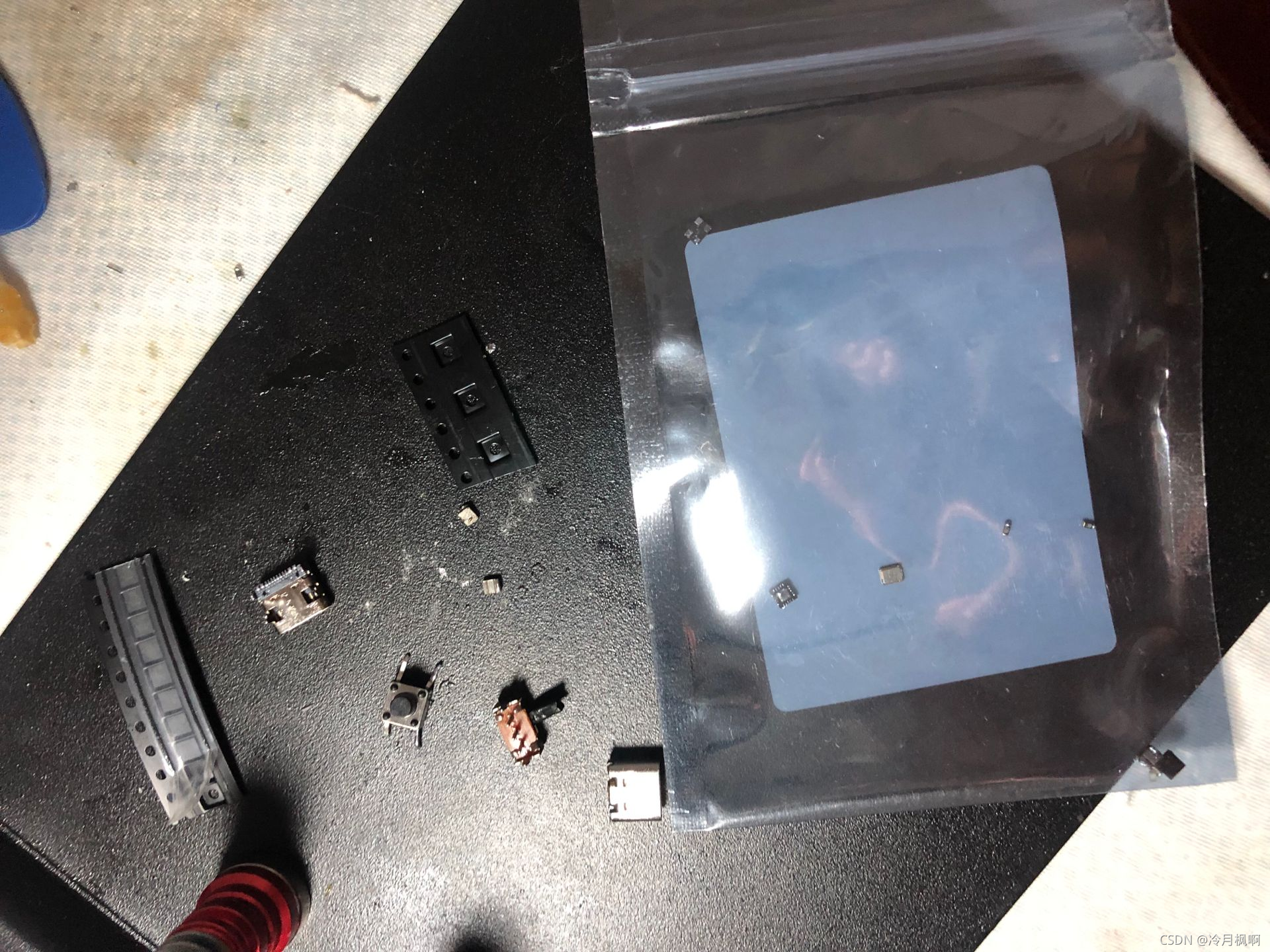
Since there was no problem with the power supply, I thought there would be no major problems with anything else, so I made a decision to remove the chip from the Lychee Pie I bought earlier (because I had an air gun, so it was easier to remove the chip), and said, Just do it, after a series of operations, I replaced the chip, woc, still not working (very helpless, USB cannot be detected, doesn’t it mean that the chip is not working, the chip is not working, check the crystal oscillator, check the voltage, (Looking at the clock), I feel there is no problem. At this point, I feel that the chip should not be broken. After all, the temperature of the chip welding will not burn out. So I soldered the previous chip to the Lychee Pi development board, powered on and tested it. Sure enough, there was no problem and the development board could be detected.
Since it's not a chip problem, what is the problem? I also searched on Baidu and found no good solution. I searched on Waku.com again, and sure enough, there were several problems that were the same as mine, but their problems were different from mine. Finally, when I looked at a schematic diagram, I found the problem. My RTC was not soldered , and the circuit was not soldered. Is such that
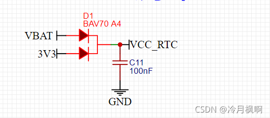 It's because D1 is not soldered, and then VCC_RTC is disconnected, and there is a problem with the clock (because this device is not placed in the power supply, so it is ignored)
So I hurriedly soldered this thing, then powered it on, and tested it. Sure enough, the USB was detected (hahaha). This problem really bugged me (it took a lot of detours).
Lychee Pie board, the chip was removed and re-soldered
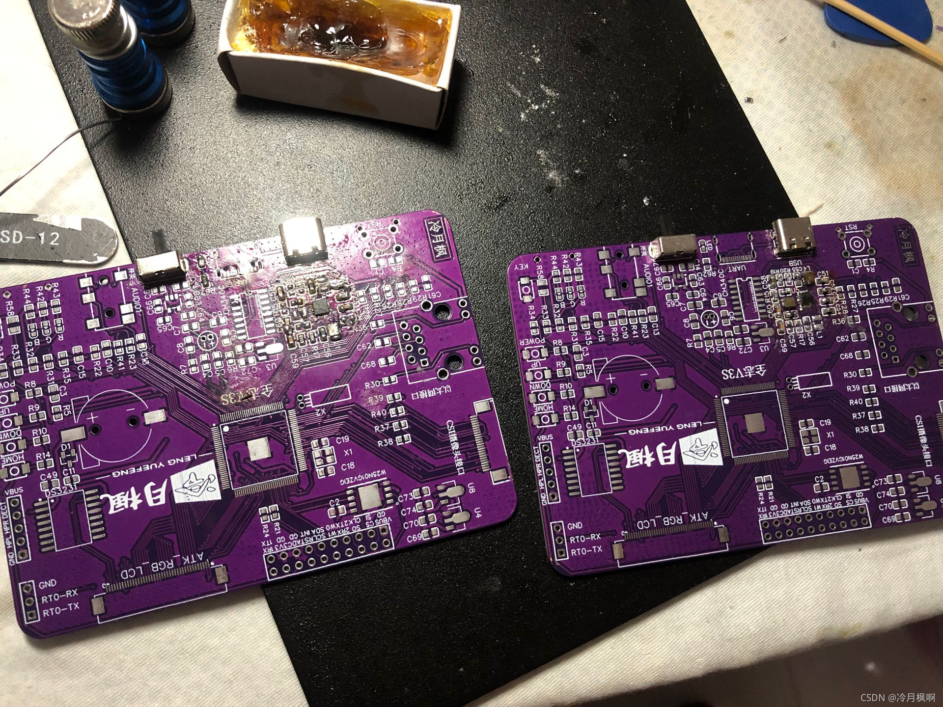
Three welded boards
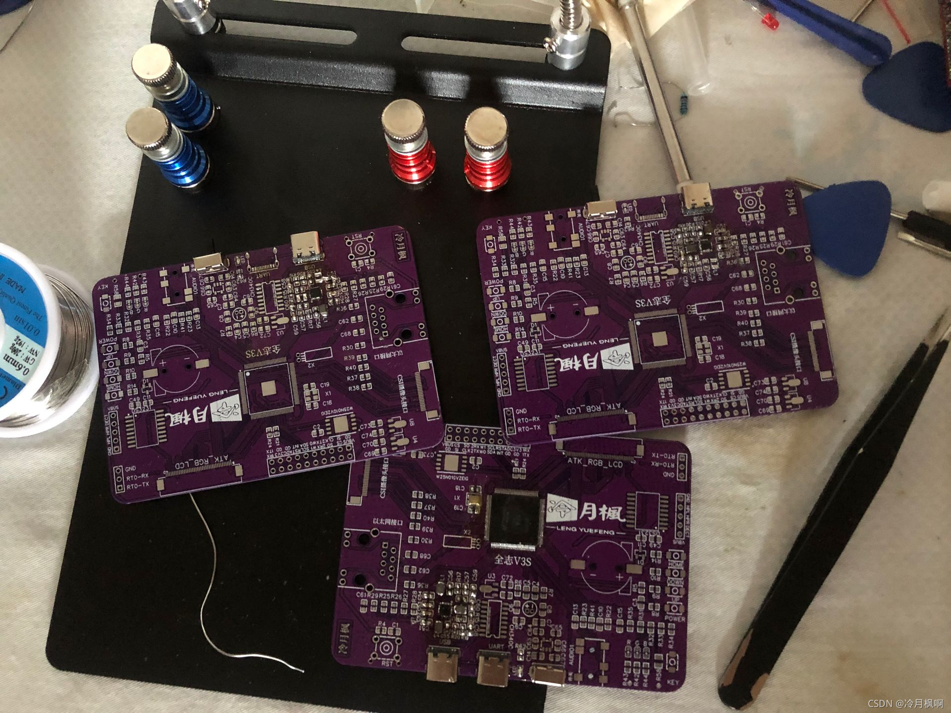
welding process
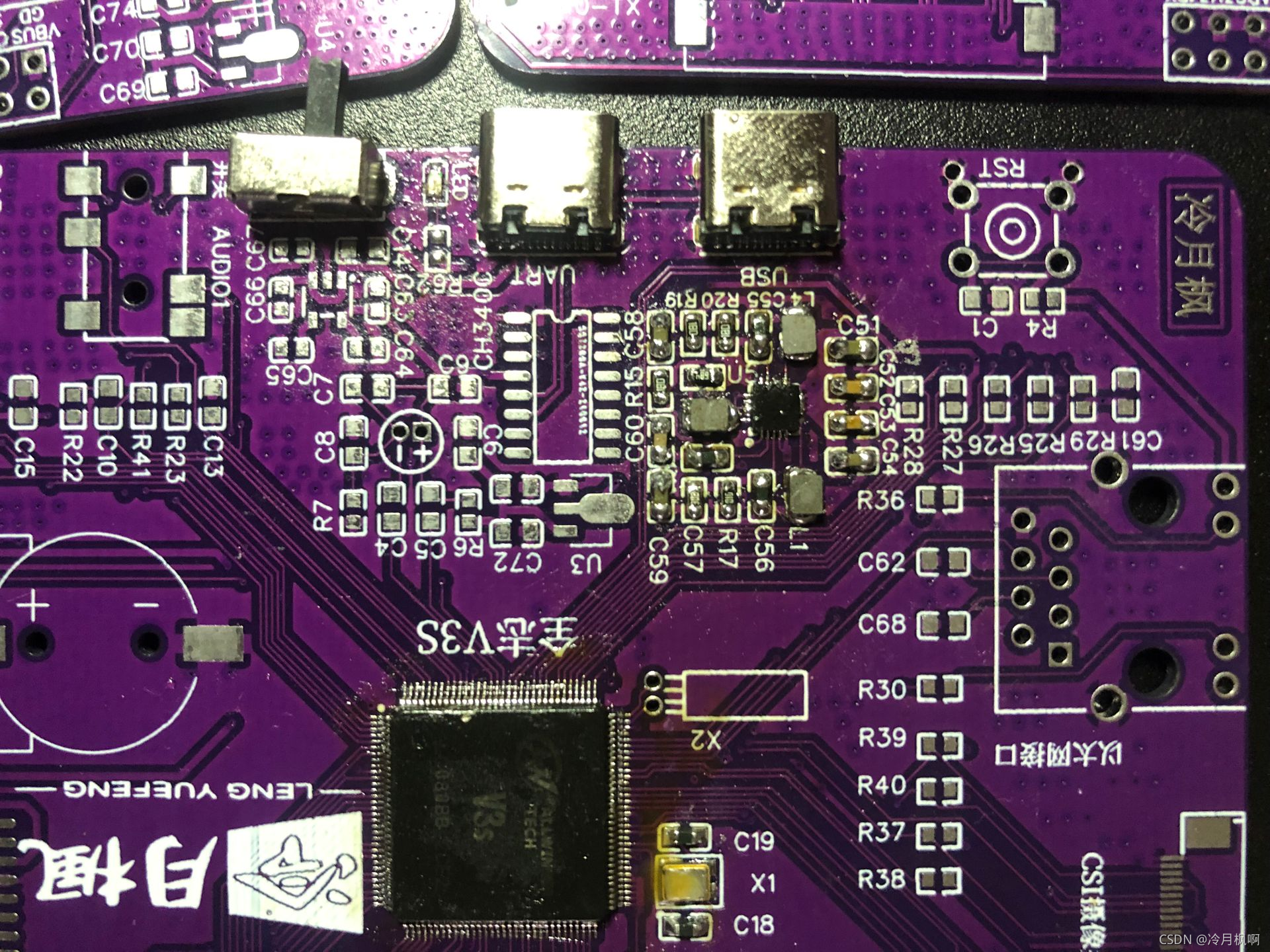
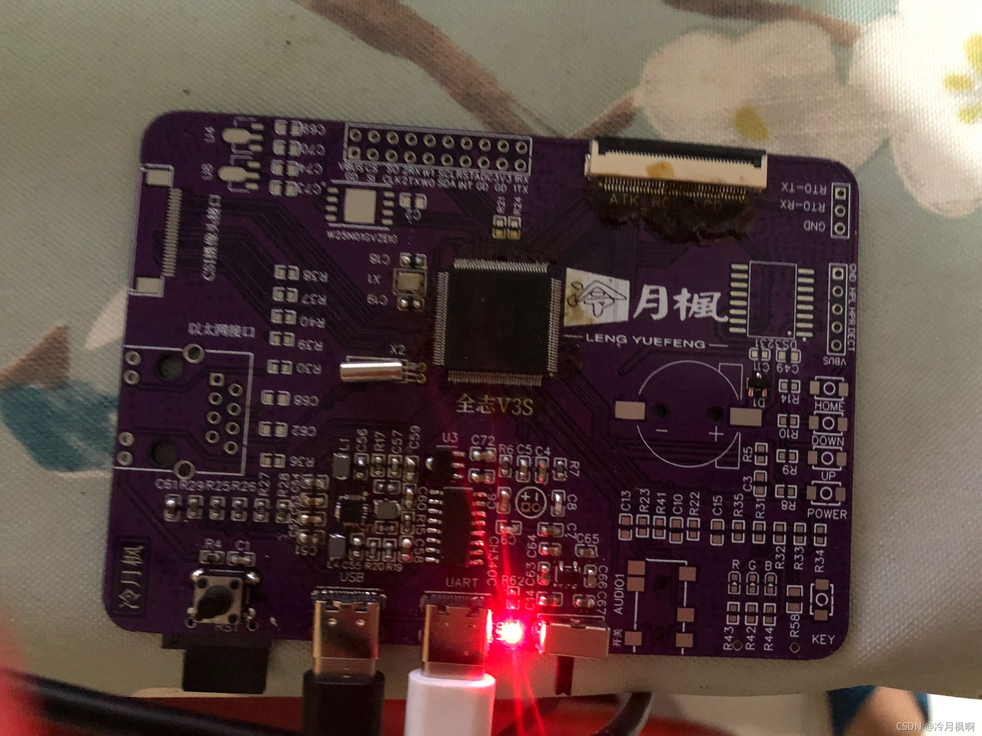
Successfully welded piece
Back:
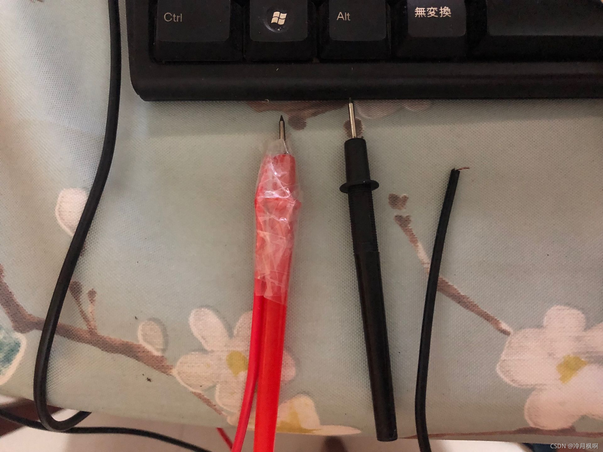
The device after 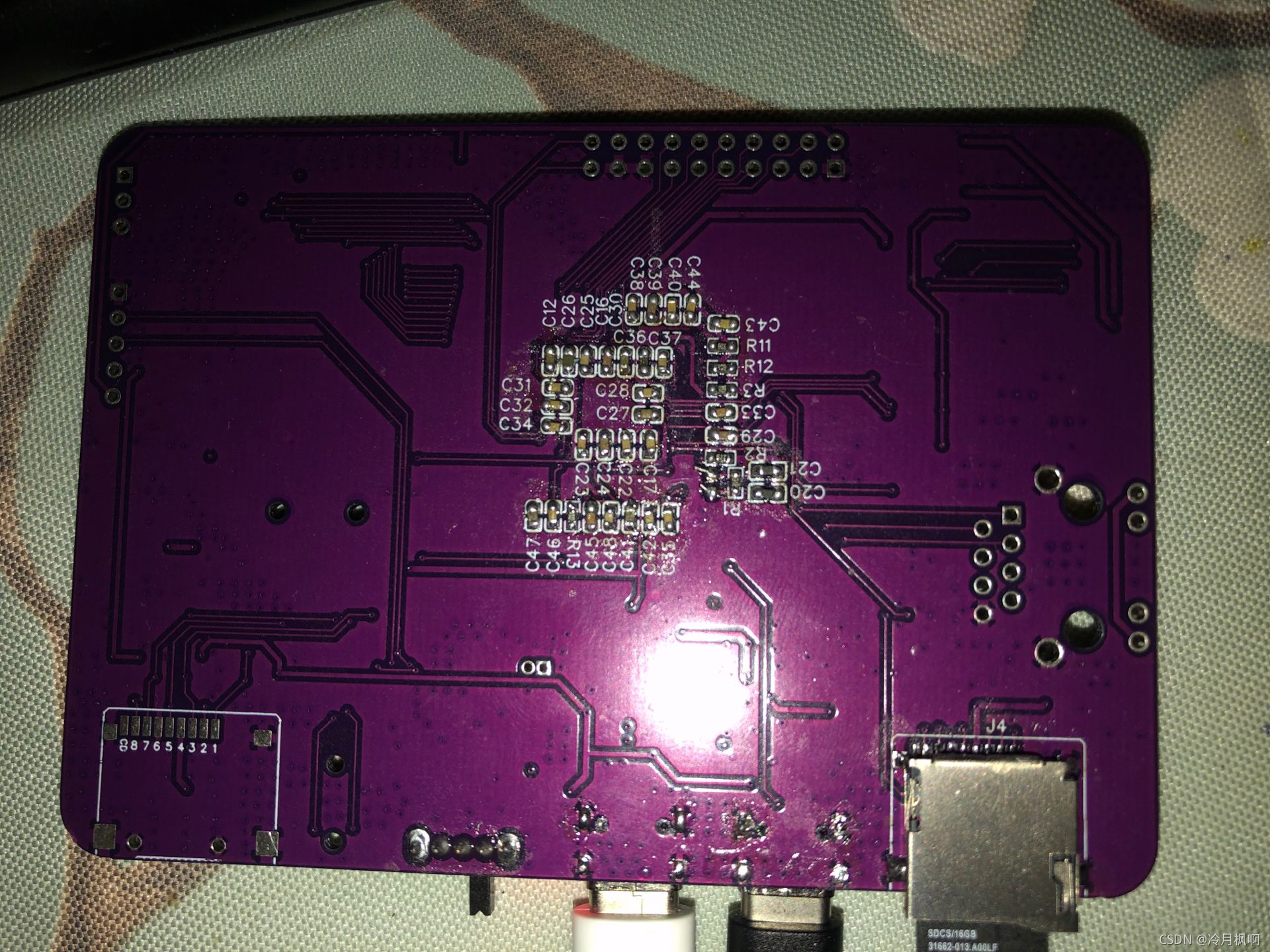 the test lead was broken during the test
USB detection can
print information through the serial port
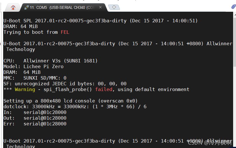
Running uboot can

Welding and debugging took several days, and only those who have experienced it will know how difficult it is. I debugged it today and I was very excited. I wrote this article to record this hard-won success (I wanted to give up several times). come on. (Now that you have taken the most difficult step, the rest of the way will be easy.)
The LED lights, buttons, Ethernet, and punctual atomic interface screens have been tested and all are normal. Other parts are still under testing and it is estimated that it will take some time to complete.
Added on 2021-09-05:
The microphone is available, and the speaker is available (the external 8002B power amplifier is used, please refer to my JQ8900 solution),
The hardware on the board has no driver for the camera (it has no ability to drive)
This part is the serial port part. There is a small design flaw here, but it does not affect the use. The power supply is connected to 3.3V, and the switch must be turned on every time to power on. This causes the serial port connection to be disconnected every time the power is turned off. It is not a big problem and can be left unchanged.
The package of the reset button is wrong, because below the reset button is the TF card slot. This button is packaged with a direct plug, which will cause the TF card slot to be welded and the button to be difficult to weld. Solution:
1. Use pliers to modify the pins of the direct plug-in button and solder them as SMDs.
2. Change the packaging of the buttons (the PCB has not been modified). Please modify it yourself (or not modify it). No other problems have been found yet. If you have other findings, you can comment and we can modify it together. I will update it as soon as I find any issues.
The camera pins I used are not official pins. The official pins should be connected to the pins of the RGB LCD screen. This means that the RGB LCD screen and the camera cannot be shared. I used another pin, but the driver is not available yet. Done, I saw from the pit website that this should be usable (MIPI interface), but it is not guaranteed to work, so be careful if you have camera requirements.

All reference designs on this site are sourced from major semiconductor manufacturers or collected online for learning and research. The copyright belongs to the semiconductor manufacturer or the original author. If you believe that the reference design of this site infringes upon your relevant rights and interests, please send us a rights notice. As a neutral platform service provider, we will take measures to delete the relevant content in accordance with relevant laws after receiving the relevant notice from the rights holder. Please send relevant notifications to email: bbs_service@eeworld.com.cn.
It is your responsibility to test the circuit yourself and determine its suitability for you. EEWorld will not be liable for direct, indirect, special, incidental, consequential or punitive damages arising from any cause or anything connected to any reference design used.
Supported by EEWorld Datasheet
EEWorld
subscription
account

EEWorld
service
account

Automotive
development
community

Robot
development
community

About Us Customer Service Contact Information Datasheet Sitemap LatestNews


Room 1530, 15th Floor, Building B,
No.18 Zhongguancun Street,
Haidian District,
Beijing, Postal Code: 100190
China
Telephone: 008610 8235 0740
 京公网安备 11010802033920号

 CS-2917


