In fact, the main controller accidentally burned down. I had something to do at school and no time...
DIY hot-swappable keypad based on QMK firmware and supports VIA software key modification.
This project is original and is being made public for the first time.
GPL 3.0
The following content is some experience and records of a QMK novice during the trial process. Please correct me if there are any mistakes.
This part only records the Rev1 design process, screenshots, etc. do not represent the final product! Content is for reference only.
QMK (Quantum Mechanical Keyboard) is a community-maintained open source software, including QMK firmware, QMK toolbox, qmk.fm website, and these documents. QMK firmware is a keyboard firmware based on tmk_keyboard, which implements some useful functions in Atmel AVR microcontroller. It was ported to an ARM chip using ChibiOS. It can function in a flying wire keyboard or a custom PCB keyboard.
This project uses QMK MSYSsoftware configuration and compilation environment under Windows system, which is easy and simple to install. The installation process is described below.
If you use other systems, please refer to the official website documentation to set up the corresponding environment.
First, enter the QMK MSYS project page, download the latest version of the software in Release and install it.
Open and run qmk setupthe command, this step takes a long timeBrothers who know magic can just ignore this sentence.. until shown QMK is ready to go.

qmk setupAfterwards, try to compile the keyboard firmware for the first time to confirm that the environment is set up successfully. (To prevent packet loss and missing files from causing subsequent compilation errors)
Can be input
qmk compile -kb dz60 -km defaultTo try to compile the firmware of the dz60 keyboard in the default layout. (Choose any keyboard, of course you can choose other ones to test)
If a string of OK appears and is displayed at the end The firmware size is fine, congratulations, the environment is set up and you have successfully compiled a QMK keyboard firmware for the first time.
If an error is reported, please check whether the command is incorrect, check the error message, complete the file, and try compiling again.
Successful examples (this is not the first compilation, so the number of OKs is very small):

Let's build our own keyboard firmware.
There are three important config.h locations:
keyboard/keyboards//config.h
user space/users//config.h
layout/keyboards//keymaps//config.h
Got it! Although your project does not have to create files according to official requirements.
Enter the Keyboard Layout Editor website. This is a visual keyboard layout editing website that generates keyboard layouts by adding or subtracting keys and adjusting the positions and definitions of keys. After designing your own keyboard layout, download the json file.

Setting the key name as above is to facilitate adding VIA support later. If it is not needed, you can directly name it to the name of the key you need to facilitate checking.
Enter the Keyboard Firmware Builder web page and copy the previous json file.
Wiring interface: edit keyboard connections.

Rows represents the number of rows, and Columns represents the number of columns. At the same time, you can select a certain key, adjust its row and column numbers, and make the connection confirmed, and you can also beautify the wiring.
Pins interface: Set the main control pin corresponding to the row and column.
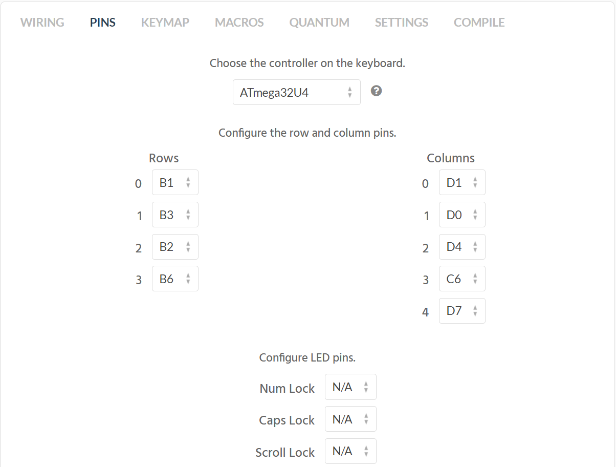
Notice! This article only explains the steps, and the illustrations are not necessarily correct operations! (As shown in the picture above, the pins are different)
Keymap interface: Select a key and edit its function on a certain layer.
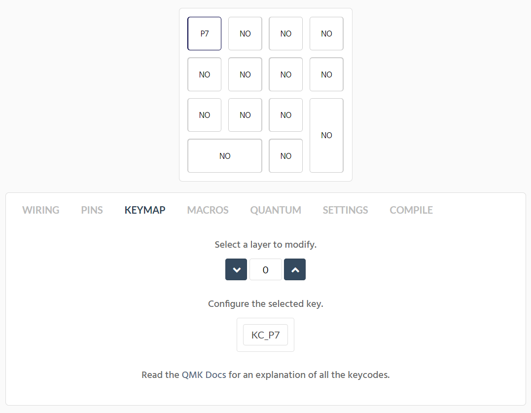
For the specific meaning of the keycode, please go to the Keycodes section of the QMK document to view it.
It should be noted that when more than one layer is used, a layer cutting key needs to be added. For specific settings, please refer to the official documentation.
Macros interface: Keyboard macro related, the author does not understand it yet, please refer to the official documentation.
Quantum interface: Big warning, changes are not recommended.

Settings interface: Modify keyboard name, capacity, number of WS2812, backlight brightness and other settings.
Compile interface: the interface to complete all settings and download firmware
If the required function is relatively simple and can be configured directly after the above steps, you can choose to directly download the .hex file and burn it.
If you need complex functions (such as oled, encoder, etc.), please download the .zip file, which contains the uncompiled QMK firmware automatically generated by this web page. We will modify it to meet your needs.
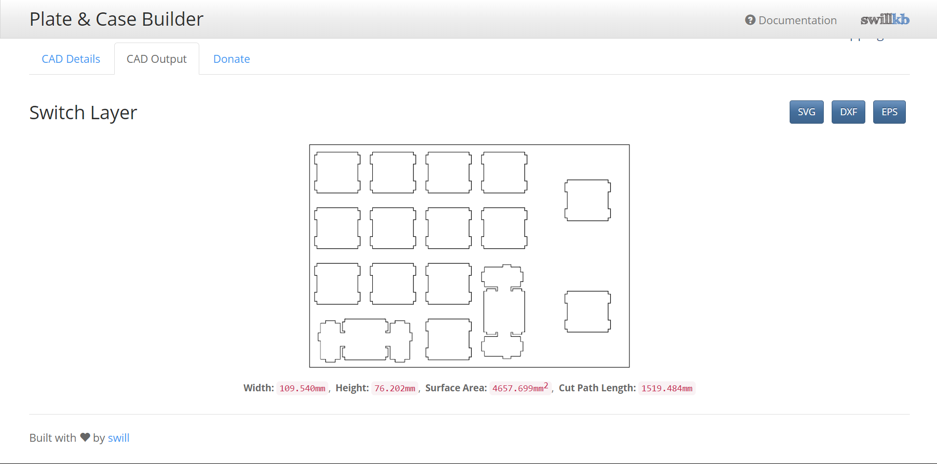
Enter Plate & Case Builder - swillkb and upload the json file of the keyboard configuration. The website will automatically generate a positioning plate suitable for the CherryMX series mechanical keyboard shaft body and steel plate satellite shaft. Just download the dxf file. This file can be used to make positioning plates of various materialsIf you want no steel, just pretend I didn’t say it.
Take my own code as an example.
First look at rules.mkthe documentation.
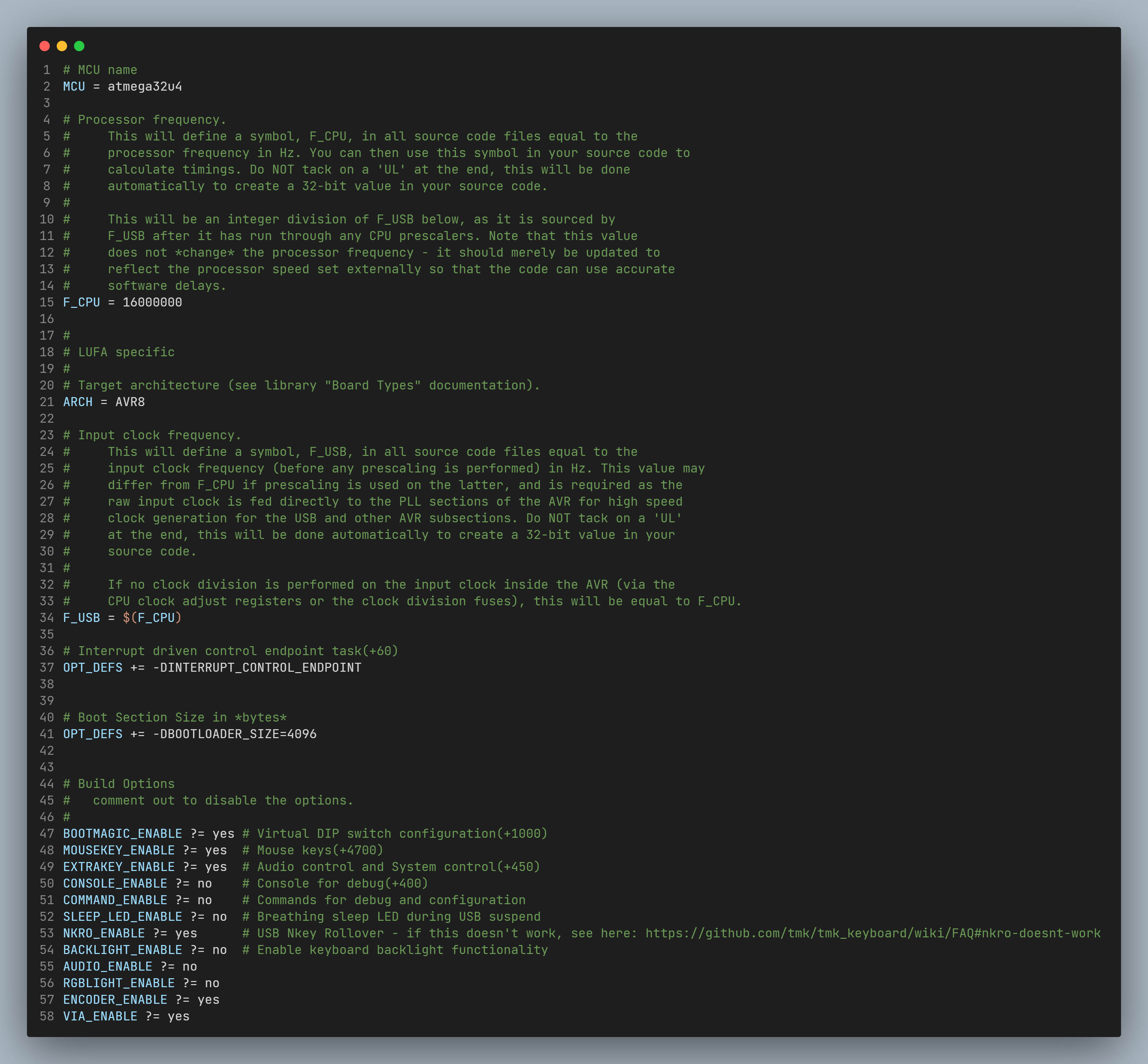
Add at the bottom
ENCODER_ENABLE ?= yes
VIA_ENABLE ?= yes
To implement encoder support and VIA support. (If you do not need VIA key change, please do not enable it)
If you need other functions, please follow the official QMK documentation to add and enable them yourself.
Secondly, nk01.hdocuments. If the initial firmware is generated by a web page, the file name is kb.h. It is recommended to modify it to your own keyboard name. Note: The kb.c and kb.h files need to be modified simultaneously, and the header file names in each file need to be modified.
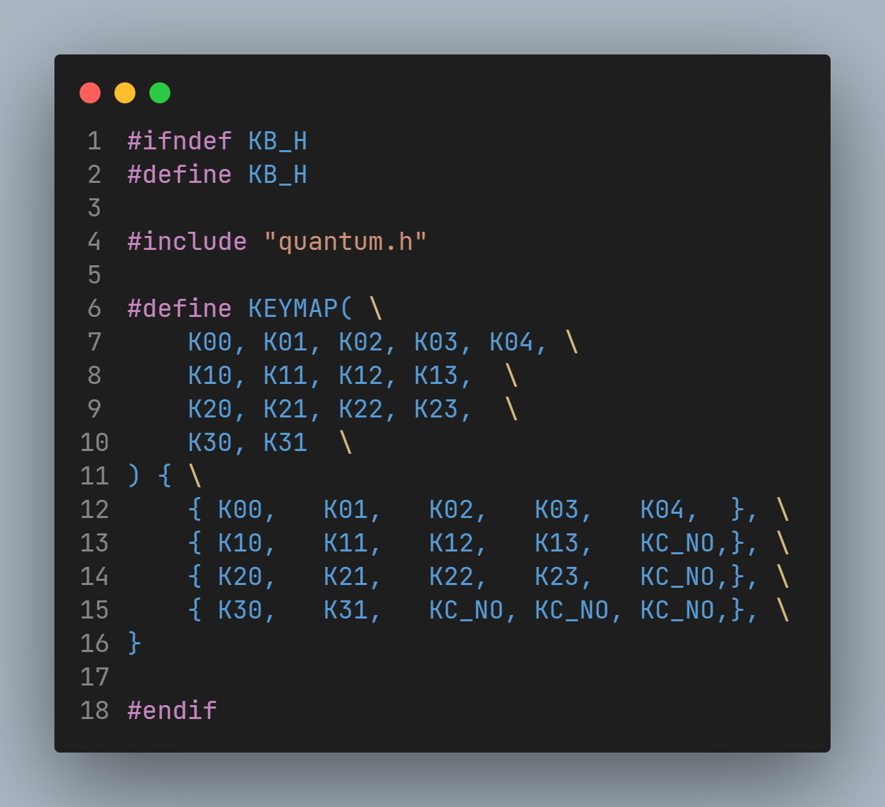
This file defines the row and column numbers of each keyboard key. Theoretically there is no need to modify it, but please make sure it is consistent with the design draft.
Then there are keymap.cthe files. This file defines the functions of the keyboard.
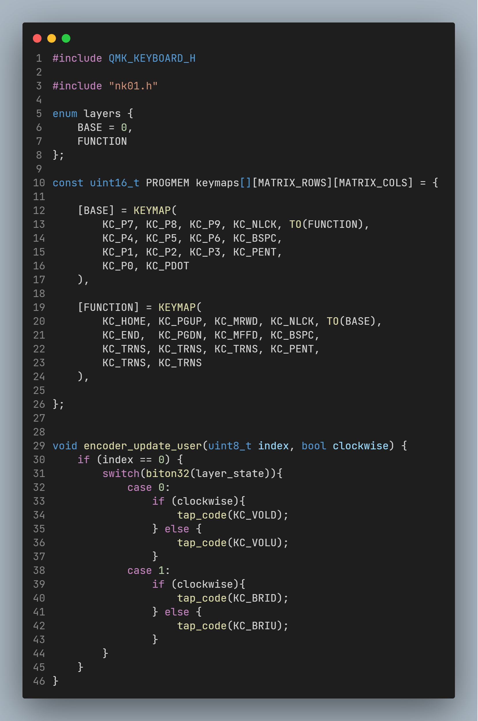
Lines 5 - 8 define the names of each layer.
Lines 10 - 26 define the key values of each layer, which can be modified according to the QMK Keycodes list.
Lines 29 - 46 define the encoder functionality. There is a deeper analysis in the QMK documentation, you can check it out if needed.
Various cutting methods:
MO(layer) Press the trigger layer, you can understand MO(layer) as Fn. When this key is released, the layer is released and restored to the previous layer. If MO(layer) is set to a key, the same key in the layer must be set to KC_TRNS, otherwise it will not return to the previous layer when the key is released. If the ESC of the 0th layer is set to MO(1), the position of the ESC of the first layer can only be set to KC_TRNS. At the same time, the MO(layer) key can only be set to the layer above the layer. For example, MO(1) can be set on layer 0, but M0(0) cannot be set on layer 1.
OSL(layer) temporarily triggers the layer. If a key is set to OSL(1), after clicking this button, only the next clicked button will be triggered from layer 1. Subsequent clicks will immediately return to layer 0 to trigger.
LT(layer, kc) can be understood as MO(layer)+kc, which can be used with one click. When this key is long pressed, the function of the key is MO(layer). When this key is clicked, the function of the key is kc. After testing by the boss, the kc here cannot be set to mod (Ctrl, Alt, GUI, Shift and other keys)
LM(layer,mod) can be understood as MO(layer)+mod, which can be used with one click. When you press and hold this key, the function of the key is MO (layer) + mod taking effect at the same time. In this way, the mod key can be used for two purposes with one click.
TO(layer) Switch to layer with one click. Can be set in any layer. For example, TO(2) is set in layer 0, but remember to finally set TO(0) in layer 2 to restore the default layer.
TG(layer) is similar to TG(layer), but can only switch back and forth between certain two layers. For example, if TG(5) is set at the ESC position in layer 0, it will jump to layer 5 immediately after pressing it. In layer 5, the ESC position can only be set to KC_TRNS. The TG(layer) key can only be set to the layer above the layer. For example, TG(5) can be set on layer 0, but TG(0) cannot be set on layer 5.
DF(layer) The default layer of the keyboard is layer 0. The function of this key is to set the default layer to layer. Do not change the default layer unless necessary.
Finally we come to the most complex config.hfile.
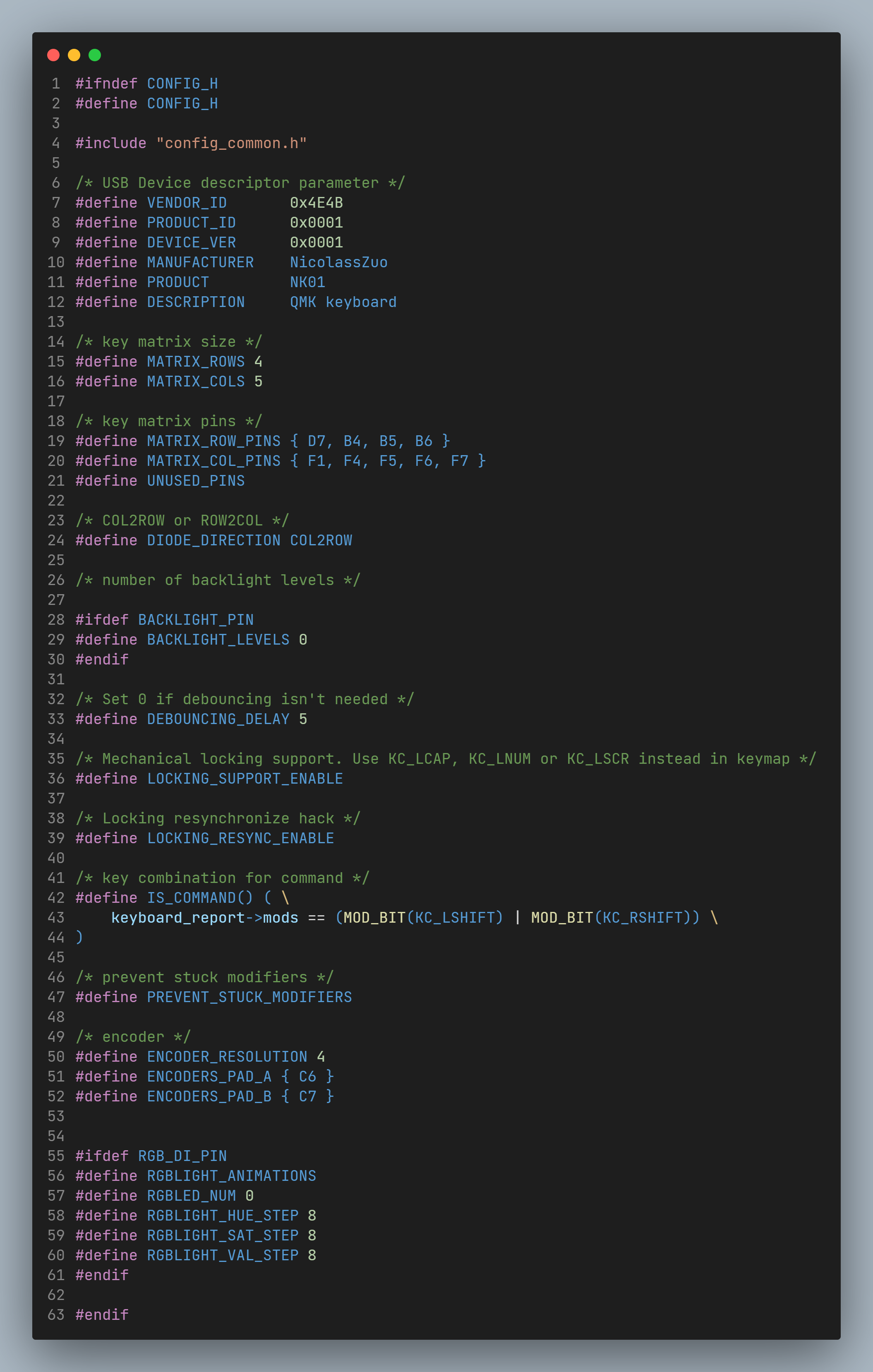
Do not change the main parts.
Lines 7 - 12 are subject to change. (If you plan to use VIA, please check the VIA section and modify it)
15 and 16 represent the number of rows and columns.
Lines 19 and 20 define the corresponding pin numbers for rows and columns.
Line 24 defines the diode direction.
50, 51, and 52 respectively define the encoder resolution and A and B pin connections.
Please consider whether to perform this part by yourself, because most users do not need to change keys frequently. If necessary, please go to the official website to download the VIA software. (The installation package is too large to upload)
VIA official website link: VIA
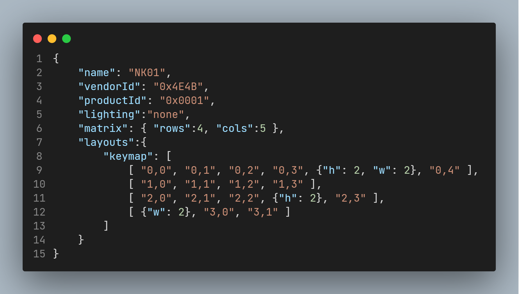
rules.mkAdd toVIA_ENABLE ?= yesstatement to enable VIA support. 2. config.hPrepare via.jsonthe document according to the document. Take my project as an example:
 the format needs to be exactly the same. Save the document.
"name": Keyboard name, which will be displayed in VIA."vendorId": That is, config.hthe VENDOR_ID in the file."productId": That is config.hthe PRODUCT_ID in the file."lighting": Lighting. I choose none because I prefer matte keyboards. If necessary, please refer to VIA official documentation."matrix": Enter the number of rows and columns respectively."layouts": For keyboards with a fixed arrangement (that is, the key length and width positions cannot be changed), just copy the RawData downloaded from the KLE website and modify it to the correct format. If it is a variable arrangement type, please refer to the VIA official documentation.3. Test the feasibility of the json file. - Open the VIA software, enter Settings, and open Design. - Enter Design and upload the edited via.json. - If successful, the following (or similar) interface will appear.
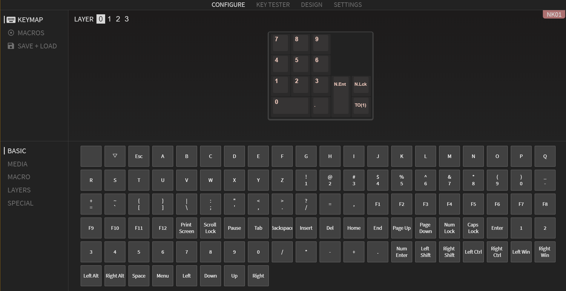
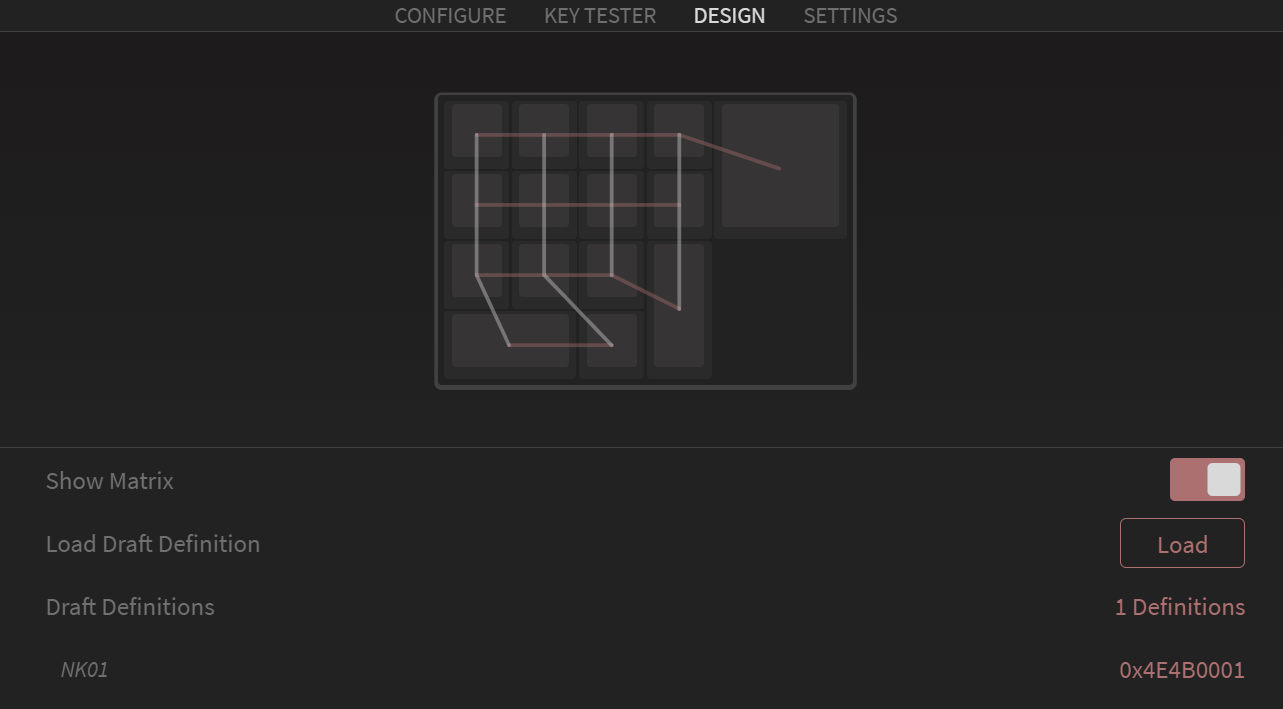 * If it fails or the keyboard layout is weird (overlapping keys, etc.), modify the json file according to the error message. * After the hardware production is completed, the key changing function can be tested. As shown below.
The above parts are all based on Rev1. The basic functions have actually been verified before burning the main control.
Open QMK MSYS, after initialization, enter
qmk compile -kb nk01 -km defaultIf it is another keyboard or other configuration, please change it yourself.
If everything goes well, a similar interface will appear.
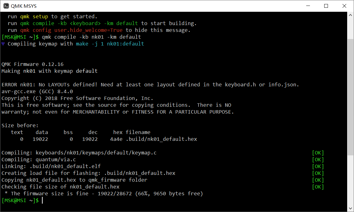
Congratulations! Keyboard firmware completed successfully!
The hardware part includes Type-C input, USB expansion, MCU main control, and control components. Please refer to the attachment to view.
The design uses ATmega32U4 as the keyboard masterThe nonsensical firmware is already written. The shaft body adopts a hot-swappable shaft seat fixation method to facilitate the replacement of the shaft body. The encoder is EC11. FE8.1 is used as a USB expansion chip (the problem is that SL2.1A has burned out many times). The Rev 1 version leads to 1 and 2 USB interfaces on the front and rear sides respectively. The side near the Type C interface is used to connect to the main keyboard.Isn't this a split keyboard?, if you use a wired mouse, you can put 2 USB at the top and 1 USB at the bottom to facilitate the wiring. Due to limited plug-in components, the Rev 2 version can only place the remaining two USB interfaces on the right side (but I have a left-handed keypad).
(The main control burned out, which prevented the completion on time)

Due to time reasons, it was not completed on time. By the end of the competition, only the QMK software part will be shared, so the BOM is not included.
Please upload a project picture containing the competition logo. The logo will be printed on the PCB in the form of silk screen printing.

All reference designs on this site are sourced from major semiconductor manufacturers or collected online for learning and research. The copyright belongs to the semiconductor manufacturer or the original author. If you believe that the reference design of this site infringes upon your relevant rights and interests, please send us a rights notice. As a neutral platform service provider, we will take measures to delete the relevant content in accordance with relevant laws after receiving the relevant notice from the rights holder. Please send relevant notifications to email: bbs_service@eeworld.com.cn.
It is your responsibility to test the circuit yourself and determine its suitability for you. EEWorld will not be liable for direct, indirect, special, incidental, consequential or punitive damages arising from any cause or anything connected to any reference design used.
Supported by EEWorld Datasheet
EEWorld
subscription
account

EEWorld
service
account

Automotive
development
community

Robot
development
community

About Us Customer Service Contact Information Datasheet Sitemap LatestNews


Room 1530, 15th Floor, Building B,
No.18 Zhongguancun Street,
Haidian District,
Beijing, Postal Code: 100190
China
Telephone: 008610 8235 0740
 京公网安备 11010802033920号

 1M1-3P3-R8/2-VS4QE


