Table of contents:
4. Power consumption calculation
6. Summary of steps (tutorial)
(Lichuang currently does not support intra-page jumps. The above hyperlinks are useless and can only be viewed as a directory)
The training objectives of the training camp are as follows:
--------------------------------
Learn circuit design, learn microcontroller embedded, and learn the Internet of Things; through actual project practice, students will be led to understand the networking, communication, and control processes of the Internet of Things; you will get an exercise in thinking about problems from the overall perspective of the project, and learn a way to access Alibaba Cloud IOT Practical methods to obtain a classic routine for transforming existing equipment into IoT equipment.
----------------------------------
This project is an IoT relay, the main control can be powered by 220V/5V;
It can control DC appliances within 30V/90W or AC appliances within 600W, and has a temperature measurement function;
Global Internet of Things, no matter where you are, you can use your mobile phone to control the on and off of the relay.


On August 18, the app interface was modified.

Attached is a detailed tutorial, you will definitely be able to reproduce it after reading it.
The tutorial is in [6. Summary of steps]
Using STM15W4K56S4 as the main controller, the EMW3080WiFi module is controlled to connect to Alibaba Cloud to communicate with smart devices (mobile phones, smart speakers, etc.), and then control the relay to implement a smart IoT device.
An industrial-grade ACDC converter is added, and the EMC design is carried out according to the manual of the ACDC module.
It can directly use 220V AC power supply to output 5V600mA and supply it to the IoT socket control board.
No need to buy additional power supply equipment.


**0809 First version PCBv1: **
----mistake----
The button is placed in the middle of the board and is difficult to press;
The power line is directly connected to the load without a filter capacitor, so the filter capacitor has no effect;
The AC wiring of the relay part is too close, the weak point and the strong current wiring are too close, and no slots are added;
----Correction----
Modified the button position and placed it on the edge of the board;
Slots were added haphazardly;
(Because I didn’t understand why the filter capacitor didn’t work, I made the mistake of not modifying the filter capacitor);
0810 Minor changes to PCBv2:
----Correction----
Pay attention to the safe distance between strong electricity and strong electricity, and between strong electricity and weak electricity (try to 3mm, consider trenching if it is less than 2mm, but the PCB strength issue must be considered);
The trench width is 1mm , and you can right-click to convert it to a slot after laying a 1mm line on the top layer.


Simply modified the positions of a few filter capacitors;
0811 Major changes to PCBv3:
----mistake----
Most filter capacitors are placed in a messy position and cannot be fine-tuned, so they need major changes;
----Correction----
Referring to Zhou Gong's wiring example, the layout of all components was modified and the PCB Layout was redone.
After the power enters the PCB, it must first pass through the filter capacitor and then supply power to the device after filtering . In terms of physical location, the power line must first pass through the capacitor and then to the device; if the device is connected first and then the capacitor is connected, the capacitor will not play a big role.

The power supply of LDO and microcontroller should also pay attention to the above mentioned, first pass the capacitor and then supply power.
(The picture below shows the input power supply of LDO)

(The picture below shows the power supply of the microcontroller, and the H key highlights the network)

USB cables do not need to be of equal length when running short distances.

Ground holes were added when laying copper to increase the reliability of grounding, and several more ground holes (vias) were added at necessary locations.

0811 PCB proofing and component ordering:
This PCB was reviewed as a puzzle. The boarding fee was 40 yuan, the coupon was 20 yuan, and the postage was 14 yuan. The total cost was 34 yuan.
I would like to remind all my friends not to make puzzles. Below are the words of Li Chuang Zhou Gong.

When I was drawing the board, I first selected the components in the Lichuang Mall, and then placed the components according to the material numbers, so I didn't encounter any problems when placing the BOM order, and the order was placed smoothly.
I hope that friends will not directly drag the resistor package from the component library to use, otherwise it will be very uncomfortable when placing orders (unless you do not order).
The 100 yuan discount coupon is just right, thank you Lichuang.

Because I have to go back to school on the 16th. Today is the 11th, and it’s hard to bring things with me, so I filled in the delivery address to the school, and the welding and debugging work will not be carried out until I return to school on the 16th.
The output parameters of the 220V power supply are 5V/600mA/3W (peak value 4.5W), and the output power is 2W greater than the sum of the above powers, which is sufficient for this project.
(The power consumption of the device is generally in the "Electrical Characteristics" category. I would like to remind those who don't know how to check the power consumption.) (I don't understand the specific parameters. I can only judge by feeling. What I read above I don’t know if the data is what I want, I hope someone can give me some advice)
Figure 1 (below)

Figure 2 (below)

Figure 3 (below)

I returned to school on August 16, and got the PCB board and components under heavy epidemic prevention obstacles from the security guards. I went back to the dormitory and soldered. This was the first time I used solder paste and a heating plate to solder.
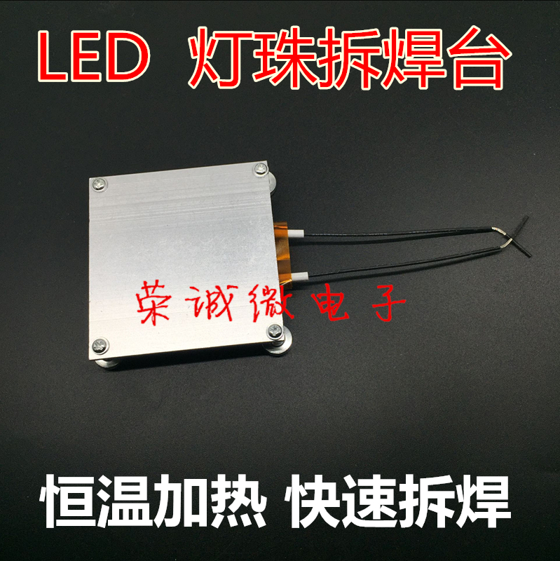
Due to the power limit in the dormitory, when I was using the heating plate shown in the picture below, the power in the dormitory was cut off and I was almost punished.

Back to the topic, the PCB that was soldered for the first time, its 51 minimum system part was very normal, and then the firmware was updated for the EMW3080 (how to update the firmware? https://www.yuque.com/lingyao/jing/isdnec ). But at 23:00 in the evening, the test found that the TX and RX of the serial port 2 of the 51 (the serial port that communicates with the EMW3080) were short-circuited. I tried to repair the soldering countless times, but the error was not corrected, so I soldered a second board (below). The picture above is newly welded), I didn’t sleep all night.

At 4 o'clock in the morning on August 17, there was actually no big problem when soldering the second piece. I didn't use solder paste. I used a soldering iron and solder wire, but the small USB interface was a big problem. [ I applied too much tin, and the tin entered the inside of the USB connector, causing the data cable to be unable to be inserted] , and the serial port download program became impossible. This mistake is very fatal. The components on my hand are only enough to solder two boards. If I can't solve it, it will be equivalent to losing the qualification of outstanding students.
The micro USB interface is difficult to remove. I spent a lot of effort to remove the micro USB connector with a red soldering iron tip, but this also caused some damage to the printed circuit. Fortunately, the TX and RX lines are still there. With trembling hands, I reconnected the micro USB connector several times, and finally successfully connected it. Finally, with the addition of external power supply (pay attention to the common ground), the second board was successfully resurrected and the program can be downloaded normally. I downloaded the program (universal) provided by Song Gong.
Stayed up all night, so exhausted. I took a short nap before configuring the network. I still don’t quite understand the principle.
At 6:30 in the morning on August 17, I found where to connect the network. It turned out to be here. Scan the QR code in the picture below for the first time to download the app. Then scan it again in the discovery device and you will be prompted. You enter the password for the WiFi you are connected to.

At 12:11 on August 17, after the PCB is powered on, send the triplet information through the serial port in the following format. You can get {"CMD":"OK"}, indicating that the writing is successful.

Then send {"CMD":"Read"} through the serial port to get the written triplet information and check whether it is correct.

8月17日晚20点,听了宋工的讲解,发现这里要设置为一键配网,如下图,修改后,参考直播课的演示,即可正常配置此设备连接阿里云生活物联网平台。
配置好后,测试继电器通断的控制,发现继电器没有反应,依次测试51引脚输出电压,反相器和继电器驱动器的各引脚连接情况,发现是驱动器接地引脚虚焊(下图),补焊之后,继电器控制功能回复正常。

至此,实物制作告一段落。

第一步
图1如下


图2如下

图3如下

下图是创建好自定义功能后的功能列表,

第二步
注意1,设备面板可进行自定义设计,是傻瓜拖拽式的,大家自己尝试。
注意2,填写配网引导时,应选择自定义配网,选择一键配网(图5)
图4.1如下,

图4.2如下,

图5.1如下,

图5.2如下,这里的“2”点击之后直接点保存即可。

第三步
图6.1如下

图6.2如下

图6.3如下

平台部分设置完成,下面介绍嵌入式部分。
这里默认你已经焊好板子,硬件没问题。
先对EMW3080进行固件更新,固件在附件有,刷固件的步骤参考后面连接(如何更新固件?https://www.yuque.com/lingyao/jing/isdnec)
首先给51单片机下载程序,程序在附件【STC15W4K_阿里云物联继电器_宋工代码】。
注意下载器的配置,注意点如下图,

下载好后通过串口连接单片机,通过串口助手(波特率115200)按如下格式发送刚刚记下的信息,此操作只能进行一次,若要进行第二次,可重新下载宋工程序,下载时勾选图7所示选项。
{ "CMD":"Write", "ProductKey":"a1FJkYjvol1", "DeviceSecret":"bdc0f8db84bb3b2e18f302a7035b2084", "DeviceName":"4cDKZBRVV6pkZWiPs2S3", "ProductSecret":"7eMpbHjKjkd2oHiq" }//到此为止,不包括此注释,没有换行
图7

串口发送操作的部分截图,如下
发送后会得到单片机返回的**{"CMD":"OK"}。
再通过串口发送{"CMD":"Read"},可得到已写入的三元组信息(下图),可进行检查是否正确。
以上操作正确完成后,即可进行配网。
【配网操作】如下:
让你旁边的朋友给你开一个热点(最好是2.4GHz的),你用手机连接,之后去生活物联网平台,在之前的人机交互设置处-产品展示页得到下图所示二维码。手机第一次扫码会下载APP(可以不用你朋友的热点下载,用自己流量下载完之后再连回朋友热点),安装好APP后,点击APP首页右上角的加号,再点击右上角的扫码图标,扫描之前你取得的二维码(不会有人扫我的吧不会吧不会吧)。

之后长按PCB板上的程序按键至三个LED快速闪烁。
之后手机端则输入Wifi密码,选中“我已完成以上操作”,开始连接,等待片刻即可连接成功,PCB上的LED,3灯慢闪、1灯快闪,表示连接正常。
此时可以通过手机控制PCB上的继电器,同时PCB上的程序按钮短按也可控制继电器,手机端同步显示继电器通断状态。
手机端可离开WiFi热点区域,只要有网(数据连接或者其它Wifi或者其它任何联网方式)即可控制PCB继电器;而继电器需保持在原Wifi的范围内才可受到控制,继电器离开Wifi区域后再返回,会自动重连,无需用户操作,重连后即可恢复受控。
以上就是本项目的全过程。
若要更换控制继电器的手机,长按PCB的程序按键至三个LED快速闪烁,重复前面的【配网操作】即可。
这里列出BOM表里立创买不到或者太贵的东西,需要的话直接点链接。
其它的通过BOM表一键下单,精准匹配,没错的,我放置元件都是按料号放的(除了保险丝座)。
① STC15W4K56S4-30I-LQFP48 ( STC15W4K56S4 贴片48脚 ):淘宝网-芯龙信电子-全新原装STC15W4K56S4-30I-LQFP48 单片机 STC15W4K56S4 贴片48脚;
③ 庆科阿里云IOT-EMW3080v2-P(板载天线),前面连接是零妖推荐的,我买的是这个12块钱的。12块钱的需要自己刷固件,附件里有【EMW3080配套固件.zip】,零妖的语雀有写EMW3080刷固件的教程;
本工程的两块PCB(主控板和ACDC)都已经过实物测试,可以正常工作。
程序功能包括物联网开关功能和温度测量上报功能都已实现。
1.串口不断返回ERROR,这可能是由于EMW3080的固件版本不对,请按照本文【7.元器件购买】中③的说明。重新刷写固件。

ROM 56KB,RAM 4KB,供电3.3V。简单易用,省去晶振,ROM、RAM空间够用,还可以使用IAP命令擦写内部Flash(省去外加EEPORM);
(ROM = 56KB > code = 14372 byte ≈ 14KB)
(RAM = 4KB > data + xdata = 9.2 + 1674 byte ≈ 2KB)

优点体积小,缺点不好焊。
The common blue relay on Taobao is Songle's [ SRD-05VDC-SL-C ] model, with AC power of 2500W and DC power of 300W;
This project uses Huike’s [ HK4100F-DC5V-SHG ] model, with an AC power of 750W and a DC power of 90W;
The control voltages are all 5V. The latter is smaller in size and has sufficient power, so the latter is chosen;
The [ NUD3105LT1G ] produced by ON Semiconductor is highly reliable, easy to use, and the circuit is simpler than the traditional triode driver.
【05】indicates the withstand voltage value. This driver can be replaced by the following chips
【NUD3112LT1G】
【NUD3124LT1G】
【NUD3160LT1G】
When the STC microcontroller is powered on, the pin will output a short high level, and then it will change to the level set by the user;
In order to ensure the reliable reset of the relay (which itself is turned on at a high level) and prevent the relay from being turned on accidentally when powering on;
Add an inverter and use the microcontroller to output a high level (low after inversion) to turn off the relay, and a low level (high after inversion) to turn on the relay.
Two voltage regulators are used, namely [ AMS1117-3.3 ] and [ ME6215C33M5G ];
[ AMS1117-3.3 ] The power supply current reaches 1A>400mA, which can supply power to WiFi modules that consume large amounts of power;
[ ME6215C33M5G] The power supply current reaches 350mA>10mA, which supplies power to the main control part that consumes less power. It also has an enable terminal that can be connected to a button to reset the MCU after power failure;
Select the [ EMW3080V2P ] model module produced by Qingke ;
Comes with MiCO-AT transparent transmission firmware, users can easily and quickly add wireless communication functions to embedded devices, greatly shortening the development cycle;
The firmware used in this project is in the attachment. It is best to flash the firmware before using it after buying it;
[ DS18B20 ] Temperature sensor is a commonly used temperature sensor that implements temperature measurement function.
Finally, I would like to write a sentence. The code given by Song Gong is really good, so I should study it carefully.

All reference designs on this site are sourced from major semiconductor manufacturers or collected online for learning and research. The copyright belongs to the semiconductor manufacturer or the original author. If you believe that the reference design of this site infringes upon your relevant rights and interests, please send us a rights notice. As a neutral platform service provider, we will take measures to delete the relevant content in accordance with relevant laws after receiving the relevant notice from the rights holder. Please send relevant notifications to email: bbs_service@eeworld.com.cn.
It is your responsibility to test the circuit yourself and determine its suitability for you. EEWorld will not be liable for direct, indirect, special, incidental, consequential or punitive damages arising from any cause or anything connected to any reference design used.
Supported by EEWorld Datasheet
EEWorld
subscription
account

EEWorld
service
account

Automotive
development
community

Robot
development
community

About Us Customer Service Contact Information Datasheet Sitemap LatestNews


Room 1530, 15th Floor, Building B,
No.18 Zhongguancun Street,
Haidian District,
Beijing, Postal Code: 100190
China
Telephone: 008610 8235 0740
 京公网安备 11010802033920号

 57-21SUGC-B013-TR8


