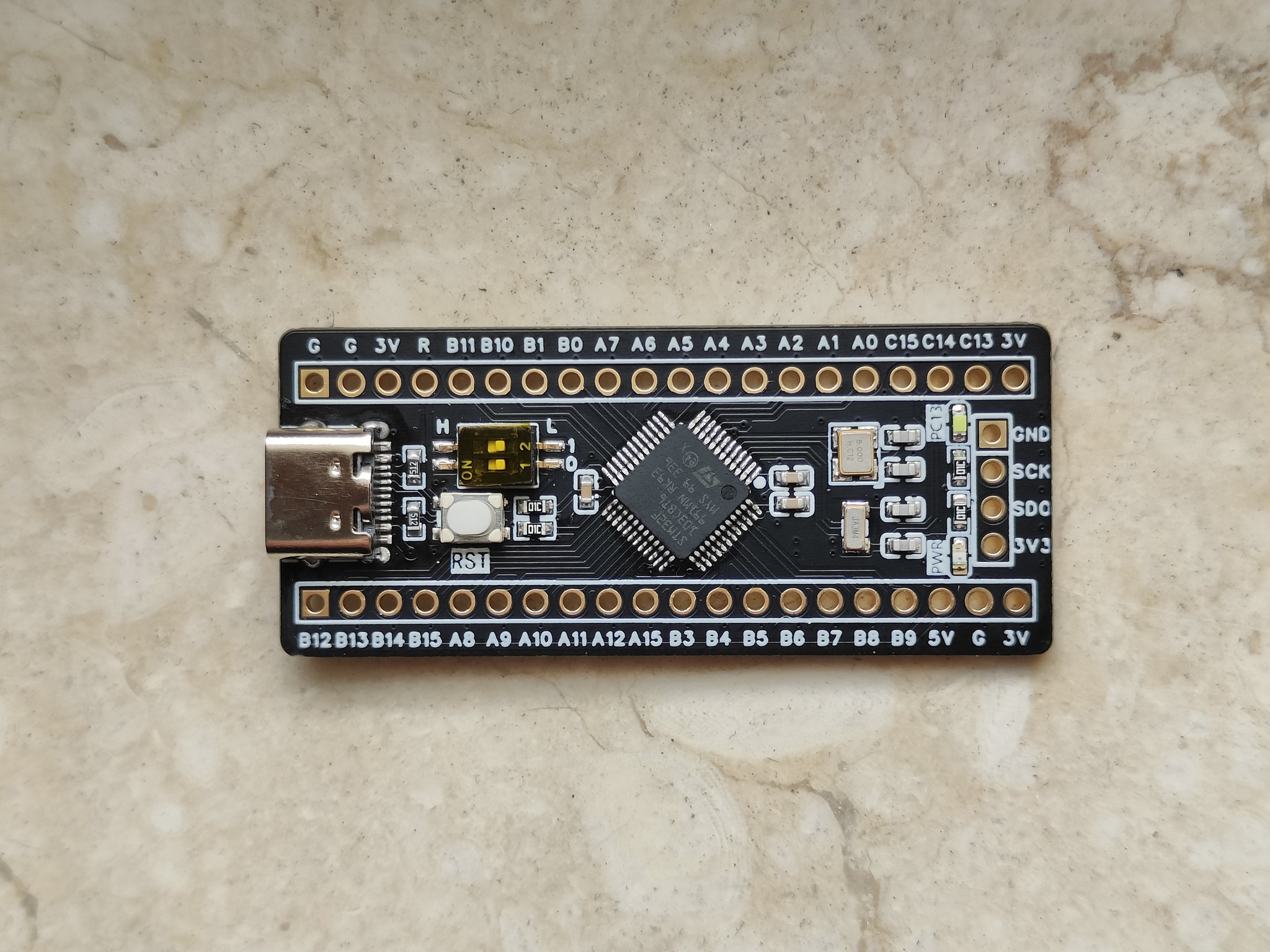
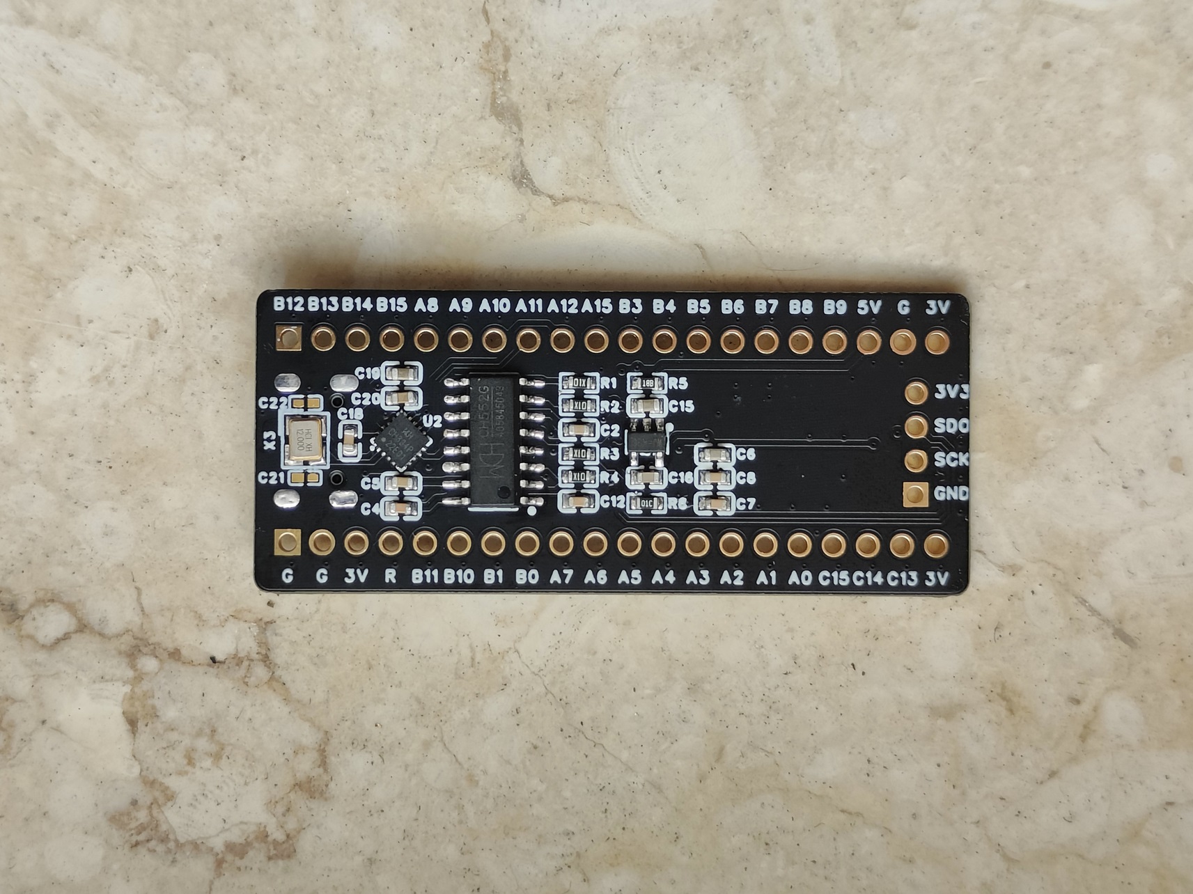
the STM32F103 development board, whose layout is consistent with common STM32 minimum system boards.
A hub chip (CH334P) is used to expand to two USB 2.0 ports: one for the STM32's internal USB controller and the other for a DAPLink (with serial port).
A single USB interface can handle programming, serial communication, and USB peripherals.
A simple little design, nothing special, just for fun.
Video link:
Attached, same as the Bilibili video:
https://www.bilibili.com/video/BV1BP2qYZEYL/?spm_id_from=333.337.search-card.all.click&vd_source=6e36cb5877fc1084cf9aefe8f240bd03
Project Introduction:
A very simple PCB design,
focusing on something useless but aesthetically pleasing.
Project Functionality
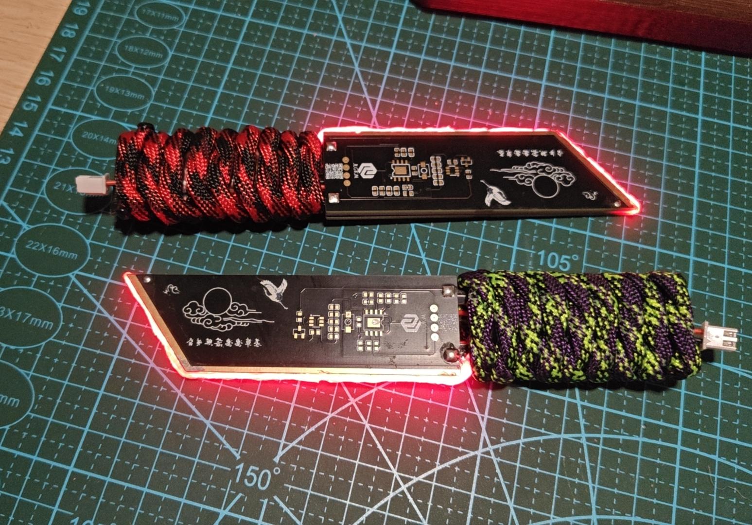
: Functions include only lithium battery charging/discharging and a touch switch, using a flexible ceramic filament as the blade.
Principle Analysis:
1. The lithium battery charging and discharging circuit

uses the classic IP5306 circuit. You can directly copy the chip datasheet. Some minor modifications were made for the design.
Testing showed that the tactile button doesn't require soldering, and
LED1 is unnecessary after assembly; it's practically invisible after assembly.
2. The tactile switch
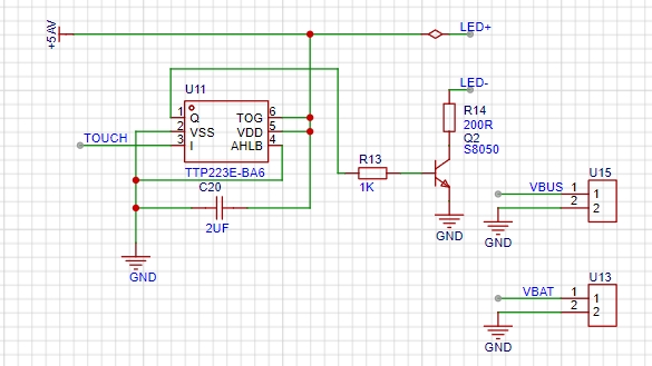
is a typical touch switch circuit. The TOUCH switch uses the touchpad. Upon triggering, it outputs a high level, turning on Q2 and supplying power to the positive and negative terminals to light the filament.
The value of C20 can be adjusted according to actual conditions; I personally found 2uF sufficient. Besides touch, proximity also triggers, creating a somewhat entertaining effect (lol).
Note:
To reduce the number of PCB fabrications, two identical circuits are symmetrically designed on the board. Only one side needs to be soldered
. Buy two flexible filaments on the same side without soldering wires. The purchase list is attached. The nominal voltage is 3.7V, but testing showed that 5V works after adjustment. This is
a special version for IP5306 power banks; the regular version may not be compatible. There may be instances where the output power is insufficient, causing automatic shutdown.
The resistance of R24 in the touch circuit needs adjustment based on the actual situation. Adjusting the filament brightness and
ensuring the frame is oversized can be addressed by exporting to a JP manufacturer to save on board making costs. However, I personally feel that JLC boards have a better build quality (perhaps due to familiarity).
If only one side of the touch circuit works after assembly, it's likely due to insufficient soldering; simply add more. Assembly process:
Take one outer shell board, solder components on any side, and connect the wires and battery according to the PCB layout .
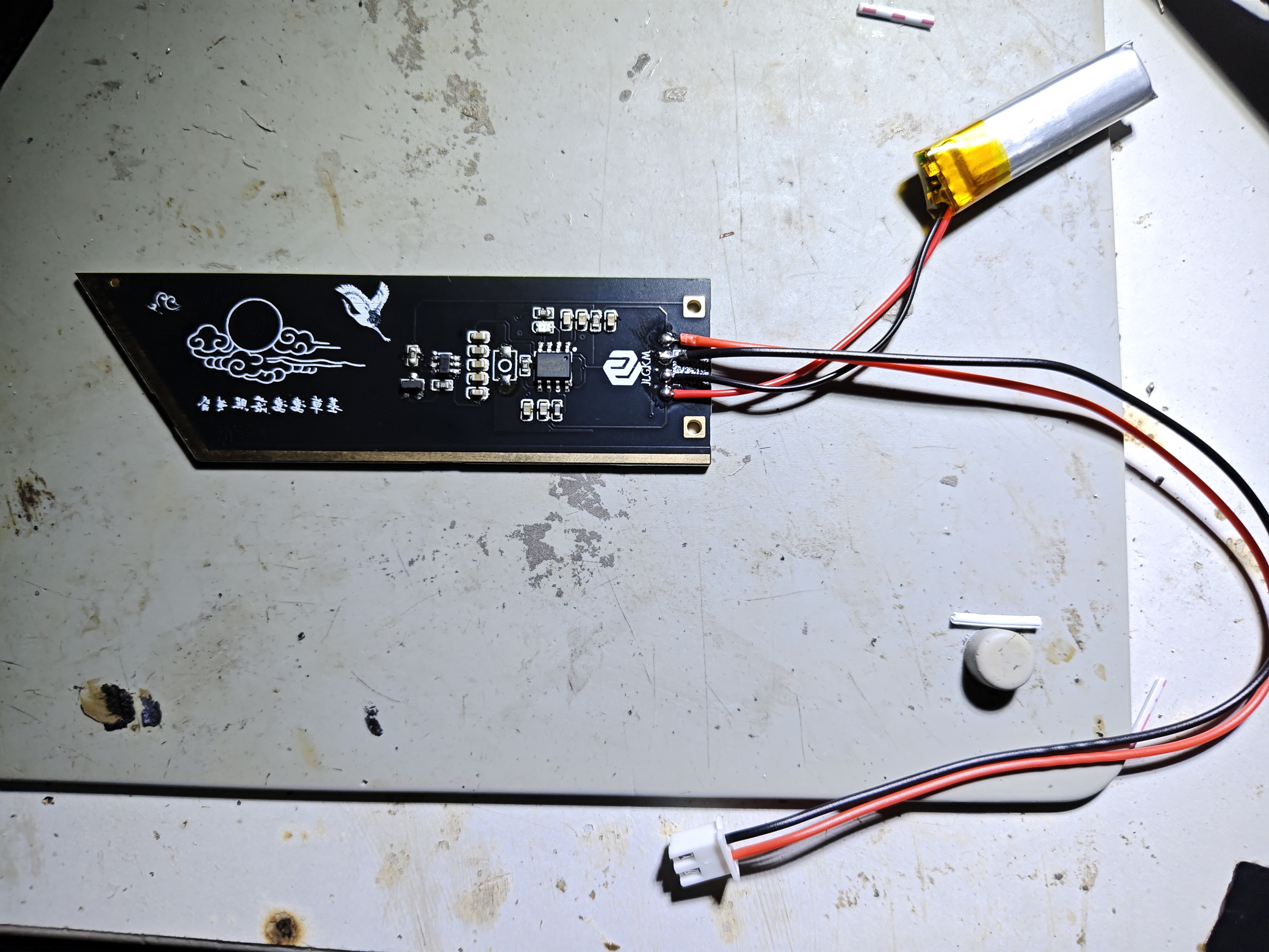
Take another frame board and solder the filament according to the actual situation (paying attention to positive and negative).

Align the two soldered boards and solder the three holes.
If the soldering is correct, the filament should light up.
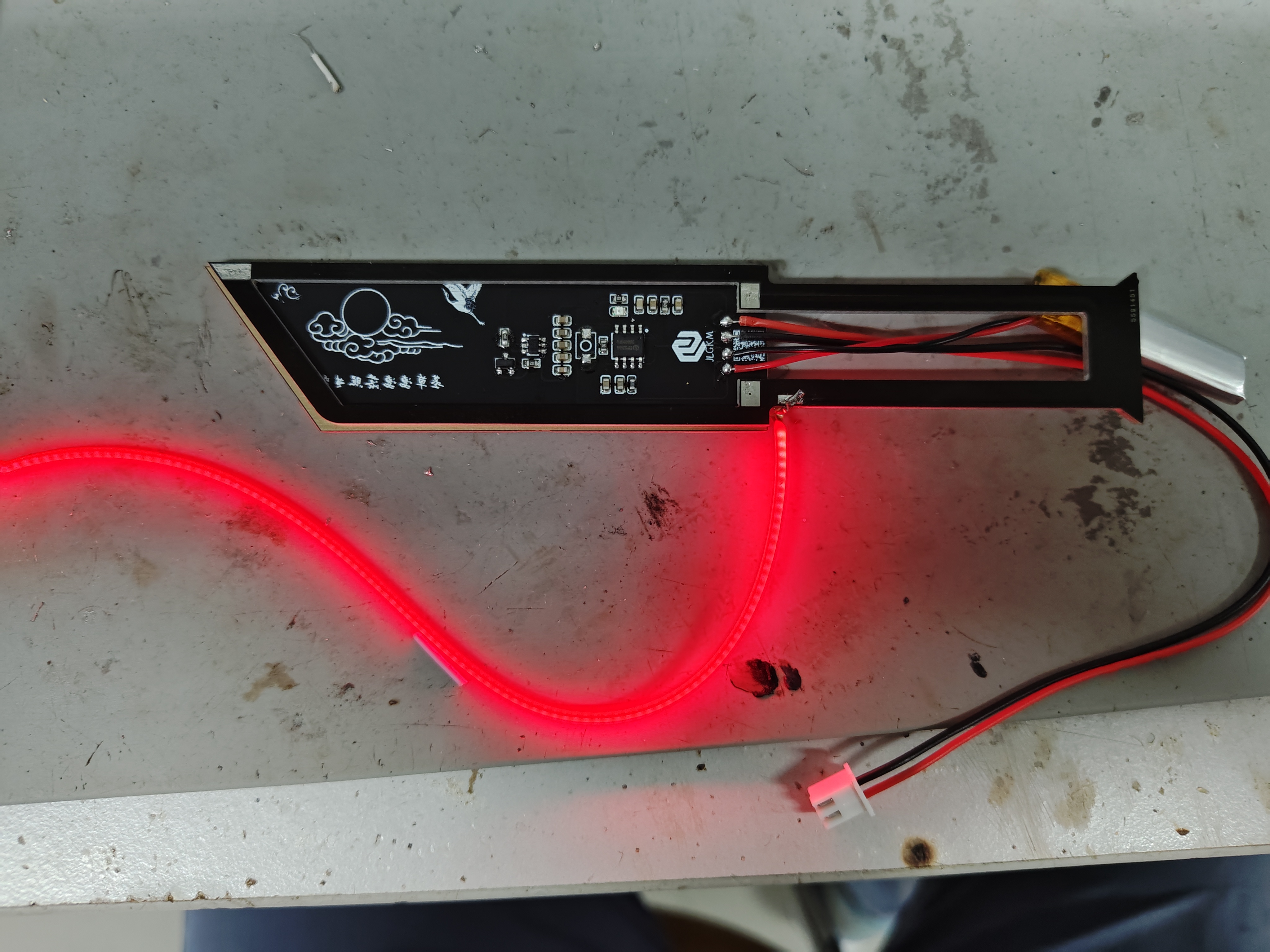
After confirming the filament brightness is correct, take another outer shell board, without soldering any components, and directly solder it to the other side. Embed
the filament into the blade's groove and secure it with hot glue. Secure
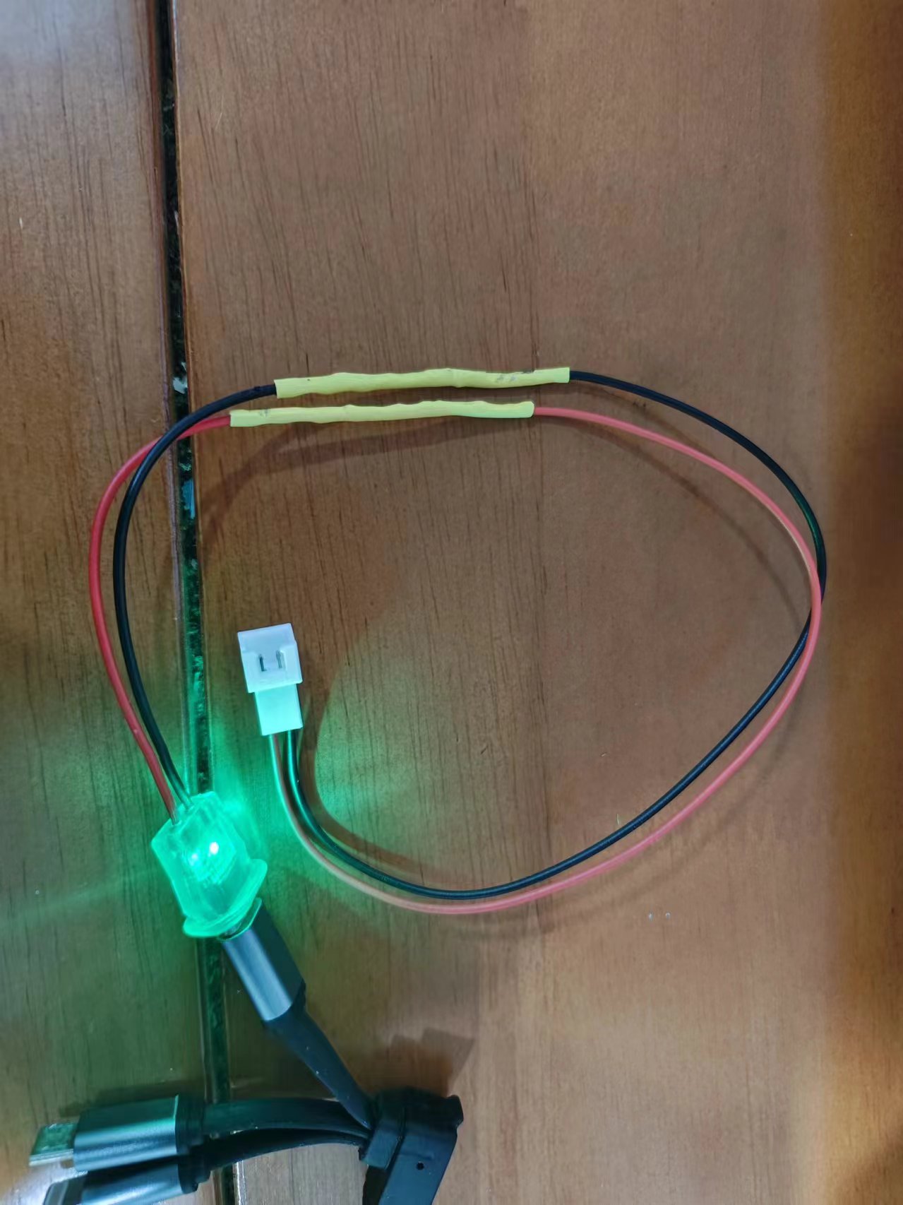
the battery and charging cable in the handle's groove, wrap it with tape, and then wrap the handle with paracord (refer to a paracord wrapping tutorial).
This link (https://www.bilibili.com/video/BV1kM4m1Q7U1/?spm_id_from=333.337.search-card.all.click&vd_source=6e36cb5877fc1084cf9aefe8f240bd03
) demonstrates how to make a matching Red Knife charging cable using a 2-pin USB-C cable.
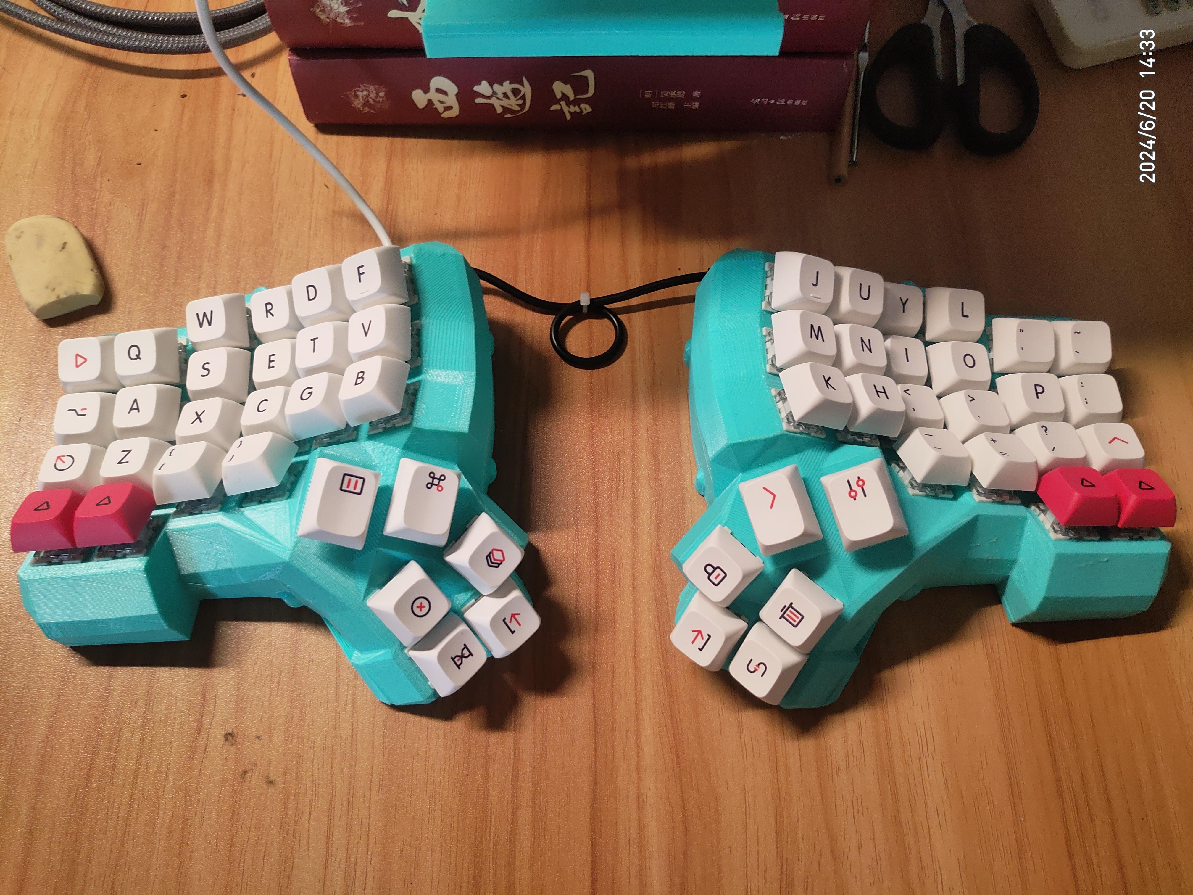
Dactyl Manuform Ergodone Keyboard with Flying Cable Reel Board for Redox STM32 VAIL
Dactyl_Manuform_Flying Wire Switch Board - V2.0
is an optimized version based on anyiyao 1.0:
It fixes a bug where vias leak solder to the back. It uses pads instead of vias
to fix a bug where row and column vias are too close together, easily causing solder bridging. It optimizes the arrangement of row and column pads, reduces the number of pads, and changes the pad shape to square.
Dactyl_Manuform_Flying Wire Switch Board - V2.1 (not tested with prototypes)
merges the middle two column pads
and changes the diode cathode connection to the left pad of the switch seat.
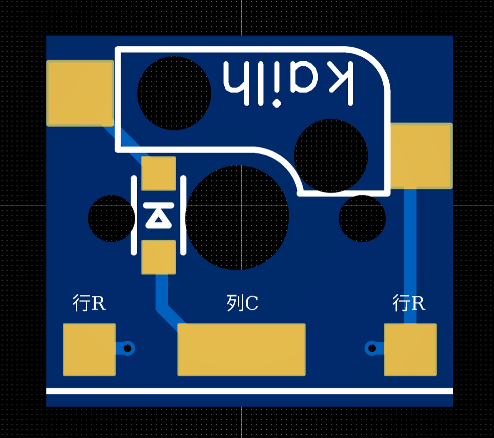
Note that
the diode is an SOD123 package, model 1N4148.
To avoid conflict between the keycap of the bottom key in the middle finger row and the housing, the switch board hole for the top key in the thumb area has been reduced. The switch board for this hole needs to be cut: cut along the white indicator line on the switch board (a file or sandpaper is recommended for polishing). Note that the placement direction of the shaft plate at this hole position is different from others. The cut side needs to be close to the inner wall of the thumb area of the shell, otherwise it will not fit.
It is recommended to make a 1.2mm thick sample board
and V-cut panel (no process edge, 6 rows and 6 columns). The sample price for 5 panel boards (180 single shaft boards) is estimated at 41.53 (excluding postage). Since the original version was drawn using the standard version of LCEDA and the shaft seat components in LCSC no longer have data, SMT placement cannot be used. The price for placing SMT on 5 panel boards is more than 250 yuan (excluding component price, only engineering fee), which is not cost-effective, so the shaft seat will not be redrawn.
Dactyl-APM
has optimized the shell interface of the dactyl manuform, drawn the bracket of APM32F103, and adapted the code simply. Currently, only the 4x6v6 layout model has been verified.
The specific bill of materials is also available in the project
: https://github.com/Byvm815/Dactyl-APM
PDF_Dactyl Manuform Flying Cable Reel Board - V2.1.zip
Altium_Dactyl Manuform Flying Cable Reel Board - V2.1.zip
PADS_Dactyl Manuform Flying Cable Reel Board - V2.1.zip
BOM_Dactyl Manuform Flying Cable Reel Board - V2.1.xlsx
91715
LM2596 module
This project was initiated due to the failure of a Newland 4G communication terminal (3.3V power supply).
This project is a modification of the LM2596S_ADJ Adjustable Power Module - LCSC Open Source Hardware Platform (oshwhub.com).
I. Chip Introduction:
The LM2596S is a step-down switching regulator integrated circuit widely used in various power conversion scenarios. It can provide up to 3A of output current and has excellent line and load regulation performance. The LM2596S includes internal compensation and a fixed 150kHz oscillator, reducing the number of external components and simplifying the design. This chip is available in fixed output voltage versions (3.3V, 5V, 12V) and adjustable output voltage versions, with an adjustable output voltage range from 1.2V to 37V.
II. Chip Parameters
: - Output Type: Provides fixed or adjustable voltage output.
- Voltage - Input (Max): 40V.
- Voltage - Output (Adjustable Range): 1.2V to 37V.
- Voltage - Feedback (Typical): 1.23V.
- Current - Output (Max): 3A.
- Current - Static (typical): 80μA (standby mode).
- Efficiency (typical): Over 80% at 12V input and 3A load.
- Package/Case: TO-220 (T) and TO-263 (S).
- Mounting Type: Through-hole or surface mount.
- Operating Temperature: -40°C to 125°C.
III. Application Areas
The LM2596S is suitable for a variety of applications, including but not limited to:
- Battery-powered devices.
- Home appliances.
- Grid infrastructure.
- Power conversion for electronic products.
IV. Chip Physical Structure
The LM2596S chip has 5 pins, including input (VIN), output (OUTPUT), ground (GND), feedback, and enable/disable (ON/OFF). The chip integrates an oscillator, regulator, comparator, and protection circuitry.
V. Package Size
The LM2596S is available in two different package types:
- TO-220 (T): Suitable for applications requiring higher power output and a larger heat dissipation area.
- TO-263(S): Surface mount package, suitable for space-constrained or automated assembly environments.
VI. Relevant Parameters
- Maximum Input Voltage: 45V.
- Feedback Voltage Range: -0.3V to 25V.
- Static Output Voltage: -1V.
- Storage Temperature: -65°C to 150°C.
- Operating Temperature: -40°C to 125°C.
- Efficiency: Varies with different loads and input voltages, but is typically between 70% and 90%.
VII. Typical Application Circuits
The LM2596S can be configured with a fixed or adjustable output voltage. For adjustable output, the desired output voltage is set using an external resistor divider, calculated as
Vout = Vref * (1 + R6/R3), where Vref is the internal reference voltage of 1.23V.
Note: Here, LED1 is closer to the Vout interface, and LED2 is closer to the input interface.
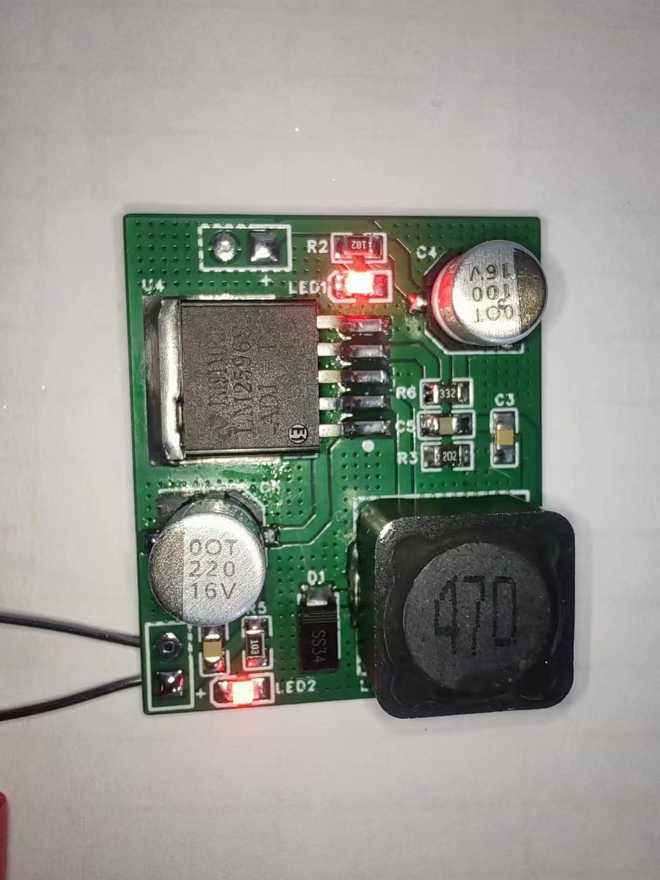
This is a repair example of a Newland device 3.3 power supply failure.
The 100uf capacitor is optional; it can be a tantalum capacitor (it seems to be more efficient) or an electrolytic capacitor.
If anyone needs a fixed voltage version or how to configure the resistors, please leave a comment.
Hand soldering is not recommended for this project due to the high component density. Unless you are an expert, disregard this.
PDF_LM2596 module.zip
Altium_LM2596 module.zip
PADS_LM2596 module.zip
BOM_LM2596 module.xlsx
91716
SmartKnob Intelligent Knob
Thanks to ran-pang for open-sourcing this.
It's a programmable haptic feedback SmartKnob smart knob, modified from ran-pang's FOC haptic feedback smart knob project, and uses the ESP32S3 module for easy soldering.
Reference Project:
FOC Haptic Feedback Smart Knob: https://oshwhub.com/ran-pang/knob
SmartKnob Original Address: https://github.com/scottbez1/smartknob
FOC Explanation Snippet: https://blog.csdn.net/K_O_R_K/article/details/123546950
Haptic Principle Reference: https://zhuanlan.zhihu.com/p/397682247
Project Description :
This project mainly originates from the domestic open-source project FOC Haptic Feedback Smart Knob. Based on the original, I modified the structure and hardware to make it as easy to solder and further develop as possible.
Software Description:
The development environment used is VS Code + Platform.io, including LVGL, SimpleFOC, etc.
Printable Description:
The 3D model is in Model.zip; adjust it according to your actual situation. For detailed
assembly instructions
, please see the knob assembly instructions v1.0.pdf file.
Open-
source materials are all in SmartKnob.zip:
1. Complete BOM, including structural and electronic components, in Hardware.zip;
2. 3D model in Model3.0.zip
; 3. Software in SmartKnob_firmware.7z
; 4. Uploaded 3MF print files and print settings instructions;
5. Knob assembly instructions v1.0.pdf
Hardware.zip
SmartKnob_firmware.7z
Demo video.mp4
Exploded view of knob assembly.mp4
knob.3mf
Print Setup Instructions.docx
Knob Assembly Instructions v1.0.pdf
Model3.0.zip
PDF_SmartKnob Intelligent Knob.zip
Altium_SmartKnob intelligent knob.zip
PADS_SmartKnob intelligent knob.zip
BOM_SmartKnob Intelligent Knob.xlsx
91718
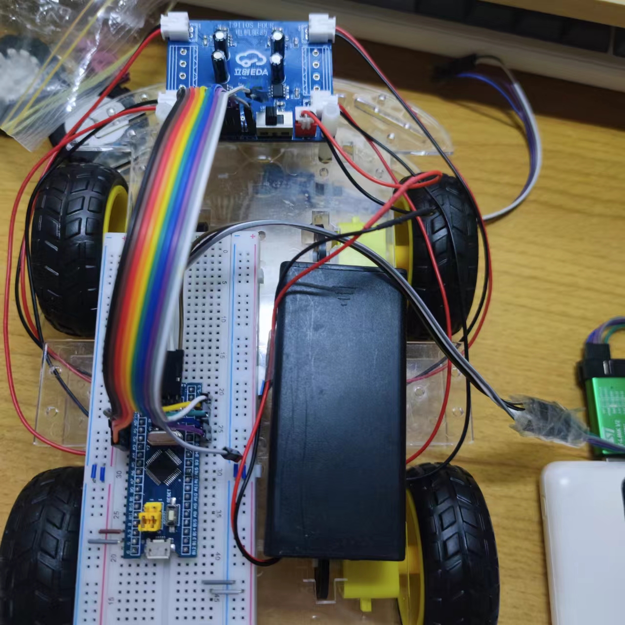
L9110S_FOUR Four-way Motor Drive Module
This project is a motor drive module based on the L9110S chip, which has four functions: direct drive for forward rotation, reverse rotation, stop, and braking.
Project Overview:
This project is a motor drive module based on the L9110S chip, featuring four functions: direct drive for forward/reverse/stop/brake.
Project Functions:
① The L9110S_FOUR has four input control terminals, which can control four output terminals to directly drive the motor's forward and reverse rotation.
② Reverse connection protection.
③ Three motor interfaces suitable for various motors.
④ The chip integrates over-temperature protection and undervoltage lockout protection functions.
Project Parameters
: Supports a maximum operating voltage of 12.0V, continuous current of 1.2A, and peak current of 2.0A.

Principle Analysis (Hardware Description):

The project was
successfully tested with an 8.4V input voltage, and the L9100S chip did not overheat.
C19272815_Stepper Motor Driver Chip_L9110S-MS_Datasheet_WJ1200821.PDF
WeChat_20241013161500.mp4
2. PWM Drives Four Motors.zip
PDF_L9110S_FOUR Four-way Motor Driver Module.zip
Altium_L9110S_FOUR Four-way Motor Driver Module.zip
PADS_L9110S_FOUR Four-channel motor driver module.zip
BOM_L9110S_FOUR Four-channel motor drive module.xlsx
91720
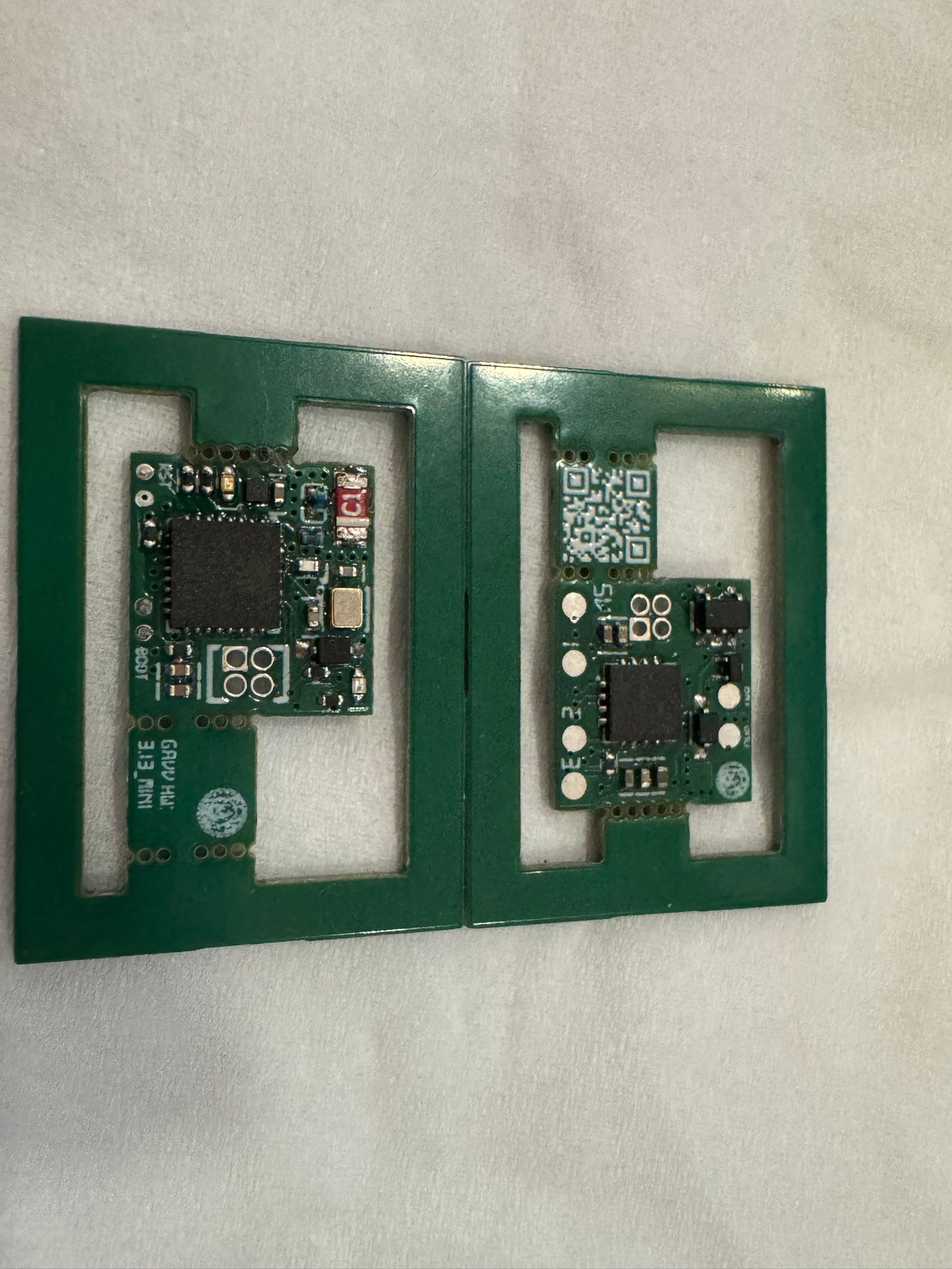
[Kamen Rider Gavv] All-Purpose Treasure Trove
A versatile, fully-equipped design based on MCP4661+ESP32C3!
Video Link:
Bilibili Video -- [Kamen Rider GAVV] Universal Open Source GAVV Battery~
Project Introduction
This project is a universal battery design based on MCP4661+ESP32C3! Very low cost~
QQ Group: 827536876
Project Functionality
Universal! Open Source! It's actually very simple; it uses a digital potentiometer to change the value of the identification resistor in real time, thus achieving universal functionality~ A 256-bit 100k resistor is just enough to achieve a recognition range from 5.6k to 62k.
Project Parameters
MCP4661 Digital Potentiometer
ESP32C3 as the main controller
TP4056 for battery charging
Software Code
GAVV_Custom_Gochizo
Please
like, comment, and subscribe! The project is complete and currently supports WebBLE network configuration. APP/mini-program development is underway!
Update Log
V3.13 Replaced the chip with MCP4661-104E, optimized some layouts for greater accuracy.
V2.11 moved the wake-up function to the charging location, ensuring it's always awake while charging. Extremely power-efficient during normal use, perfect!
V2.10 fixed instability caused by excessive capacitor removal, optimized circuit routing, and added new contacts at the charging point.
V2.6 removed the magnet wake-up function and added GPIO10 to G01 to switch between insertion and removal states (no need to remove the capacitor).
V2.4 added GPIO4 as the wake-up source connected to G02, so it wakes up simply by inserting, eliminating the need for a magnet. ~
Finished product image

PDF_[Kamen Rider Gavv] All-Purpose Collection.zip
Altium_[Kamen Rider Gavv] All-Purpose Collection.zip
PADS_[Kamen Rider Gavv] All-Purpose Collection.zip
BOM_[Kamen Rider Gavv] Omnipotent Collection.xlsx
91721
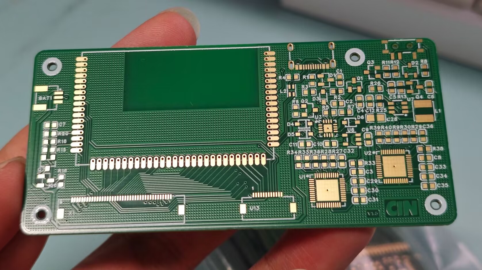
Logitech G913 schematic and modifications (verified)
The project has been verified, and the v1.5 prototype can recognize it. Some individual chips were not found or were replaced with better alternatives. The BOM (Bill of Materials) can be exported from the PCB itself.
A new project group chat has been created. Materials will be uploaded and group purchases will be organized in the group if needed: 907854382.
Updated August 29, 2024: Re-layout v1.5 and prototyped, placing the LED controller next to the main controller. The v1.5 prototype has passed recognition testing. To avoid wasting resources, it is strongly recommended to make a prototype and test it yourself first.
Introduction: This project is a schematic diagram drawn by myself based on reverse engineering of the G913, including a main controller verification board and modified reference routines. I hope everyone can make a keyboard that meets their expectations.
Estimated cost: 80 RMB per board with the main controller, 120 RMB per receiver, and multiple sets of various components can be purchased for under 100 RMB.
Tips: Main controller startup is conditional, peripheral circuit enable conditions are complex, and successful LED controller communication is required for recognition in ghub. Pay attention to the I2C pull-up resistor position and communication lines when drawing the PCB. Verify the current-limiting resistors for the LEDs yourself. The uploaded project is a backup and has some minor issues (such as component packaging). Please feel free to leave feedback in the comments section. I will gradually upload other resources later.
File tree description: The modified example is a three-piece set: main control board + axis board + encoder board, with a special 98-key layout. A CNC shell model is available; please request it from the group. The key layout of the modified example is still being verified; implementation will take a few days. The main control daughterboard is used to adapt the original main control board to a smaller keyboard space, but the packaging is very difficult to solder.
PDF_Logitech G913 Schematic & Modified (Verified).zip
Altium Logitech G913 schematic & modified (verified).zip
PADS Logitech G913 schematic & modified (verified).zip
BOM_Logitech G913 Schematic & Modified (Verified).xlsx
91722
JLink-V9-Mini-V1.0
The mini version of JLink V9 is only 1.5 x 4 cm. It features a JTAG interface with 12MB SWD and 15MB JTAG bandwidth.
The schematics and firmware are from the internet. I only modified some component packages and redrawn the PCB.
Replacing the JLinkARM.dll file in the JLink installation location will not trigger piracy warnings, and you can use JLink-related tools such as jflash and ozone.
bootloader.bin
JLinkARM.dll
Instructions.txt
PDF_JLink-V9-Mini-V1.0.zip
Altium_JLink-V9-Mini-V1.0.zip
PADS_JLink-V9-Mini-V1.0.zip
BOM_JLink-V9-Mini-V1.0.xlsx
91723
GD32F407VET6 Expansion Board
Skystar GD32F407VET6 Expansion Board
I participated in the design call for an expansion board. Previously, I'd been learning about LEDs and digital tubes, so I took this opportunity to design a communication board, including Ethernet, RS232, and RS485.

I chose the W5200 Ethernet chip, which, according to the datasheet, has the same pinout as the W5100 and W5500. The main reason was its lower price on Taobao. I'll just post a picture for reference; I
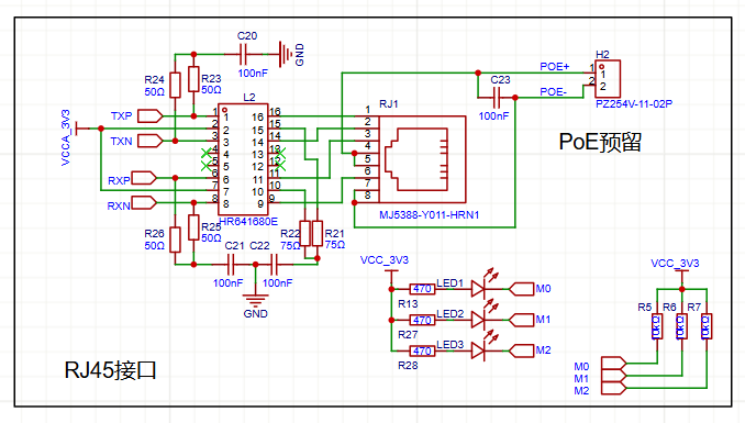
already had the interfaces and transformers on hand, so I didn't use an integrated one. Since it's a 100M chip, pin 4578 isn't needed. I also brought out the PoE power supply.

The RS232 and RS485 circuits were built according to the datasheet. Components were from the Taobao store 16-15; thanks to LCSC!

Soldering complete. I used a board from the Open Source Plaza, modified to black and white silkscreen, and tested it after soldering; it works perfectly.
LCSC has abundant resources, and the LCSC development board provides learning materials, which will keep me entertained for a long time.
PDF_GD32F407VET6 Expansion Board.zip
Altium_GD32F407VET6 Expansion Board.zip
PADS_GD32F407VET6 Expansion Board.zip
BOM_GD32F407VET6 Expansion Board.xlsx
91724
electronic


 京公网安备 11010802033920号

 ELM99302303BW-S


