[MFT] Multifunctional Touchscreen Soldering Station

This project is a multifunctional experimental tool that can be divided into two parts: a multifunctional soldering station and a multifunctional meter. Due to the extensive content, it is presented in two separate chapters.
Video Link: [Open Source] 4-inch Touchscreen Soldering Station, a somewhat strange design!!!
Through this project, what knowledge did I reinforce (and what can you learn)?
The use of Arm core CortexM4 related peripherals, the use of GD32F470 series and AT32F403A series basic libraries. Practical use of the FreeRTOS
embedded system software layered design framework
.
Design of an Android-like interface using LVGL.
Commonly used hardware circuits (op-amps, MOS, DC-DC, etc.).
[WARNING] This project involves 220V AC power; please operate with caution!!! For those who want to replicate this project, it is not recommended to do so without relevant basic knowledge!!!
Open Source License
This project is licensed under the "CC-BY-NC-SA 4.0" Creative Commons License. Please do not use it for commercial purposes. Please indicate the source when reprinting.
Open source code: https://gitee.com/yllff/fl_aio_welding_station [Subsequent code updates can be viewed at this link]
Project Attributes:
This project is being publicly released for the first time and is my original work. This project has not won any awards in other competitions.
Project Updates:
2024/10/03 Project released.
2024/10/06 Fixed known hardware issues, released V2 version, not yet board-tested.
2024/10/24 V2 version verified, IO pins have changed, latest adaptation code: https://gitee.com/yllff/fl_aio_welding_station
Project Upcoming Updates
- Fixed known hardware issues, [Currently, hardware issues are resolved using jumper wires, pending the next version update. Those who want to replicate this should not rush to board-test!!] [
Multi-function Meter UI Optimization,
SD Card Reader Function,
Heating Platform with Multi-segment Adjustable Mode]
[Multi-function Meter]
Project Introduction:
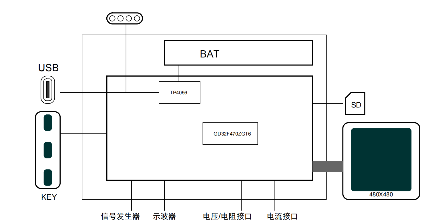
The multi-function meter integrates four functions: oscilloscope, multimeter, and signal generator. It uses a GD32F470ZGT6 main controller and is equipped with a 4-inch capacitive touchscreen with a resolution of 480x480. It has a built-in 1100mAh lithium battery. The overall dimensions are 86mm x 86mm x 15mm (L x W x H).
Project parameters
: Interaction method: 4-inch TFT LCD screen, 480x480 resolution, 3 tactile switches;
Power input interface: Type-C connector, 5V1A, magnetic socket;
Oscilloscope parameters: MCX interface, sampling rate 2MSa/s, bandwidth 10MHz;
Signal generator parameters: MCX interface, output frequency 1KHz-100KHz (software conflicts exist above 50KHz, to be resolved), peak-to-peak value 0-10V, supports sine/square/triangle/sawtooth waves;
Multimeter parameters: XT30*2, resistance range 0-40MΩ ±1%, voltage range ±200V ±1%, voltage range ±2000mV ±1%, current range ±10A ±1%, supports continuity and diode measurement.
1. Hardware:
To make the multi-function meter (hereinafter referred to as the meter) as thin as possible, it is designed with only one PCB board, and the interface also uses relatively flat plug-in connectors. The main controller is a GD32F470ZGT6. Because it needs to drive a 4-inch RGB screen, an SDRAM chip, model W9825G6KH-6I, 32MB 16bit, was added. The screen is connected via an FPC connector. Voltage and current measurements are switched via relays, then transmitted to the CS1237 chip after passing through an operational amplifier. The CS1237 is a high-precision, low-power, 24-bit Sigma-Delta analog-to-digital converter chip, commonly used in electronic scales and portable devices. The CS1237 communicates with the GD32F470ZGT6 via an SPI interface. The firmware programming port is located on the back, labeled V[VCC]D[DIO]C[CLK]G[GND]. The power
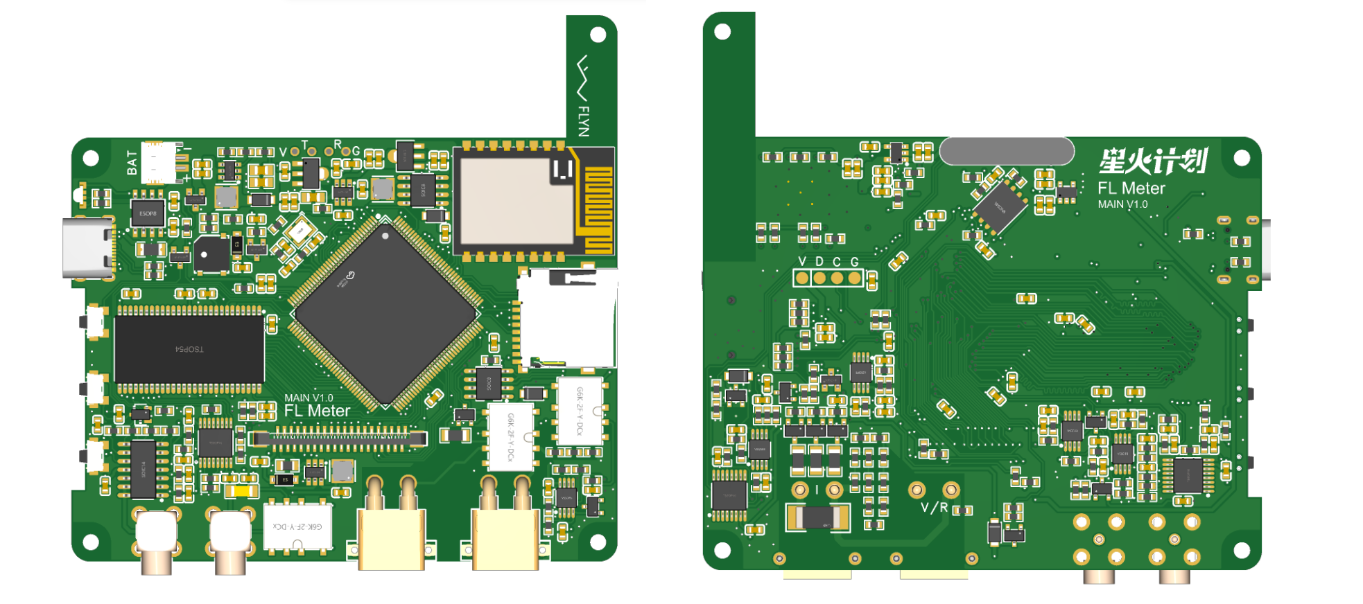
supply
can be connected via a Type-C port or a magnetic socket. The lithium battery charging chip is a TP4056, supporting a maximum current of 1A.
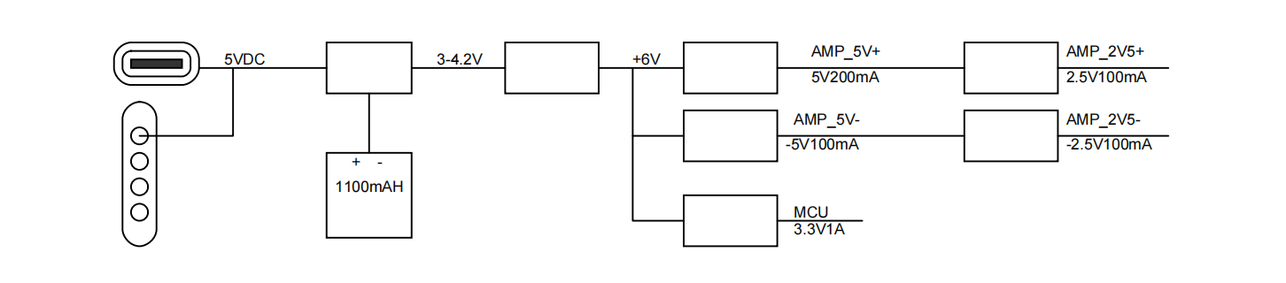
The internal power supply framework is shown in the diagram below, which boosts the battery voltage to 6V and then converts it into multiple voltages for the measurement circuitry.
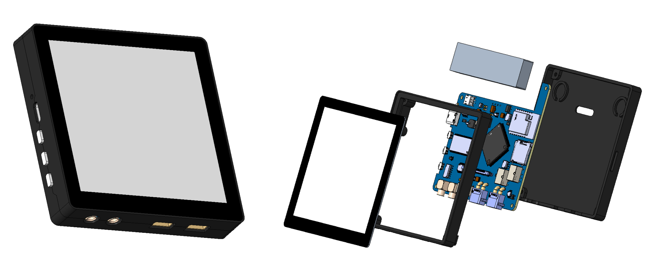
1.2 Structure
The structure of this meter is relatively simple. The capacitive touchscreen is directly glued to the upper frame, and the back cover is fixed with four M2 screws. The oscilloscope and signal generator probes are both XMC type, and the voltage and current measurement interface is XT30 type. Using these two types of interfaces can reduce the thickness of the whole device to a certain extent.
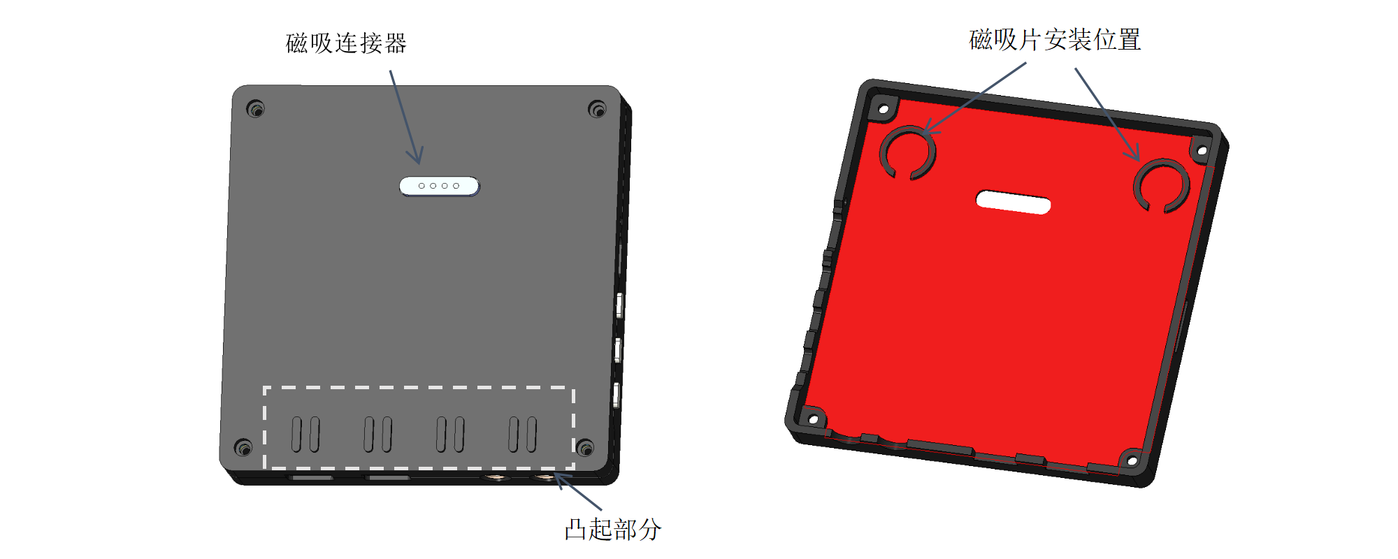
There is a 4-pin magnetic connector (pogo pin) on the back, which is used to communicate with the soldering station and can also charge the meter through the soldering station. In addition to the magnetic connector, I also added two 10mm diameter magnetic plates to the back cover and the inside of the side of the soldering station to enhance the attraction. The protrusion on the back cover can be locked with the heat dissipation holes on the side of the soldering station to bear part of the weight.
1.3 Principle Analysis
1.3.1 The power
meter has a built-in battery and needs to be turned off when not in use. MOSFET Q2 is used to disconnect the power supply. As can be seen in the figure, the MOSFET is controlled by the IO pin marked PWEON. When the SW1 button is pressed, Q2 conducts and powers on the MCU. The MCU will pull the PWRON pin low. After releasing the SW1 button, Q2 is still in the conducting state. During operation, press and hold the SW1 key to enter the shutdown interface. The MCU controls the PWRON pin to pull high, disconnecting Q2. Note that the Vbat voltage is generally between 3.7-4.2V, the PWRON pin must be set to open-drain output, and a 5V rated I/O pin must be selected.
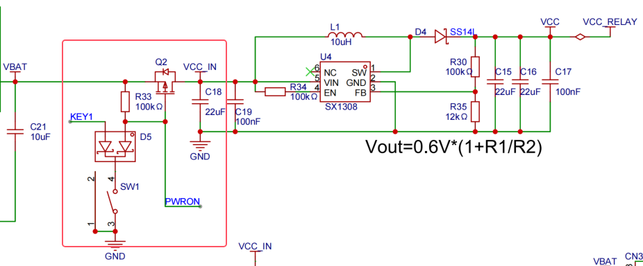
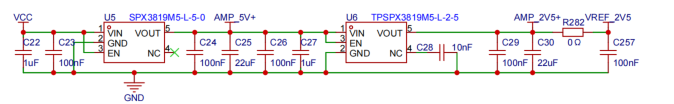
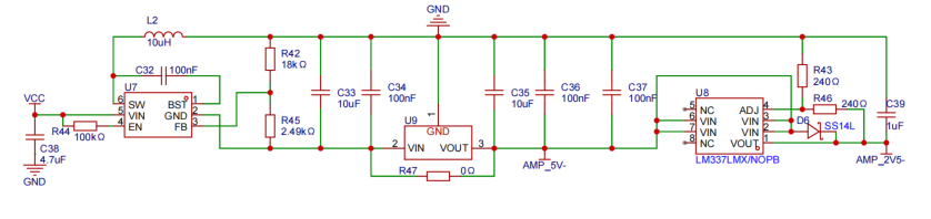
The battery voltage is boosted to 6V by the SX1308, then converted to 5V, 2.5V, -5V, and -2.5V for the measurement circuit, and 3.3V for the core circuit power supply.
1.3.2 Oscilloscope Principle
This section references the official oscilloscope expansion board, which provides a detailed explanation of its principles.
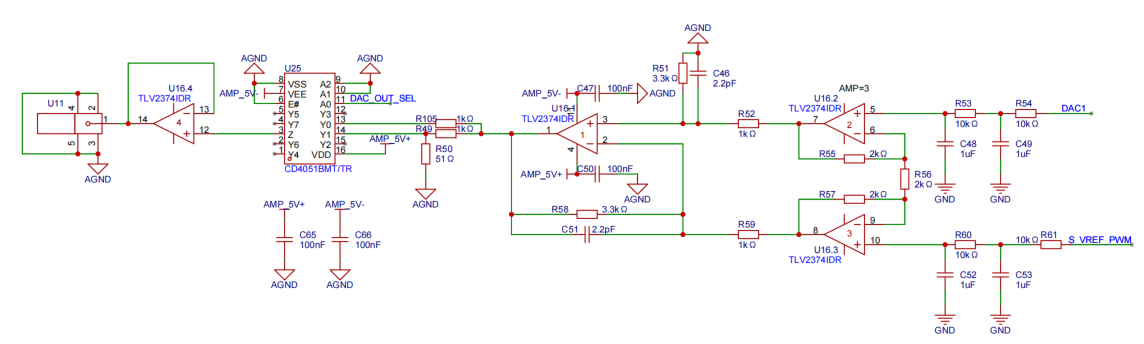
1.3.2 Signal Generator Principle
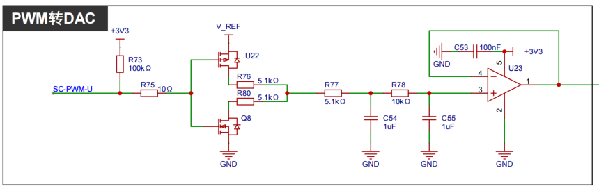
The signal generator first generates periodic analog signals, such as "triangle wave," "sine wave," and "rectangular wave," through the MCU's DAC. The signal is between 0-3.3V, then amplified to -5V to +5V by an instrumentation amplifier circuit, with a maximum amplitude of 10V. S_VREF_PWM is a PWM-to-DAC converter used for biasing and pulling the signal down. U25 can be used to select 1x and 1/20 attenuation channels.
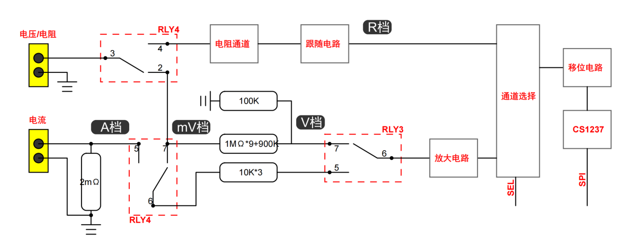
1.3.3 Resistance,
Voltage, and Current Measurement Switching: Two relays are used to switch measurement channels. Voltage and resistance measurements use the same interface, while current measurement uses a separate interface. Channel selection is as follows:
Voltage V range: [RLY4] [2, 3] are on, [RLY3] [6, 7] are on.
Voltage mV range: [RLY4] [2, 3] and [6, 7] are on, [RLY3] [6, 5] is on.
Voltage A range: [RLY4] [6, 5] is on, [RLY3] [6, 5] is on.
Voltage R range: [RLY4] [4, 3] is on.
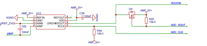
The CS1237 communicates with the MCU via an SPI interface. The CS1237 is powered by 5V, requiring a level shifting circuit. The CLK pin is set as an open-drain output and pulled up to 5V. The DOUT pin is also set as an open-drain output, and the DIN pin is pulled down. When the DOUT output level is low, the CS1237's DOUT pin is pulled high; when the output level is high, the CS1237's DOUT pin is pulled low by the pull-down resistor on the DIN pin. When reading from the CS1237's DOUT pin, pull DOUT high to open-drain, and read data from the DIN pin. All these I/O pins require a 5V withstand voltage.
2. Software
: As is customary, FreeRTOS + LVGL is used here, with Keil 5.38 as the IDE.
2.1 GUI Design:
SquareLine Studio + CodeBlocks is recommended for GUI development. First, use SquareLine Studio to quickly design the initial UI, then import it into CodeBlocks for simulation and debugging on the PC, and finally import it into Keil for compilation and download to the MCU for debugging. This saves a significant amount of time.
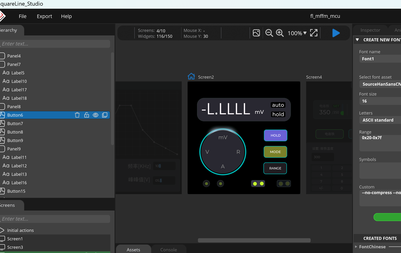
We can roughly set up multiple interfaces first. If you are a free user and need to design more than 5 interfaces, you can create multiple projects. [Also, if you don't know how to use some functions or animations, you can set them up here and generate .c files to view them.]

CodeBlocks can directly simulate code. If some code needs to be adjusted, you can use CodeBlocks to simulate and adjust it first, saving compilation time.
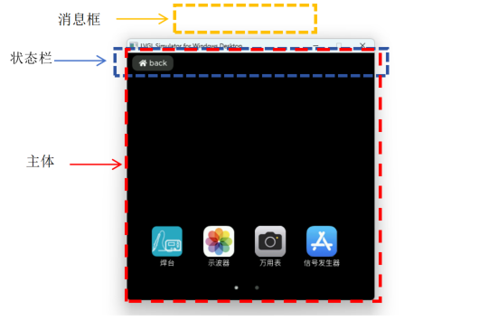
2.1.1 The UI framework interaction
table uses a capacitive touch screen. I plan to design a UI framework similar to the Android system. Currently, it only implements the app's click-to-jump function to enter the application. This screen is divided into 3 parts: the main screen, the status bar, and the message box. To save RAM, the updates for interface switching are all in the main screen. When entering a new application, the controls in the previous main screen will be deleted. The status bar contains a back button, which will exit the application and return to the main screen when clicked.
//--ui_statusbar.c
static void btn_homeback_click(lv_event_t *e)
{
if(ui_main_screen.app_close!=NULL) {
ui_main_screen.app_close();
ui_main_screen.app_close = NULL;
}
lv_obj_del(ui_main_screen.current_desktop);
ui_main_screen.current_desktop = lv_homepage_load();
}
//-- ui_homepage.c
static void homepage_icons_click(lv_event_t *e)
{
lv_obj_t *screen;
ui->page_select = lv_tabview_get_tab_act(ui->tabview);
app_icons_data_t * app = (app_icons_data_t *)(e->user_data);
if(app->open!=NULL) {
lv_obj_del(ui->screen);
ui_main_screen.current_desktop = app->open();
ui_main_screen.app_close = app->close;
}
}
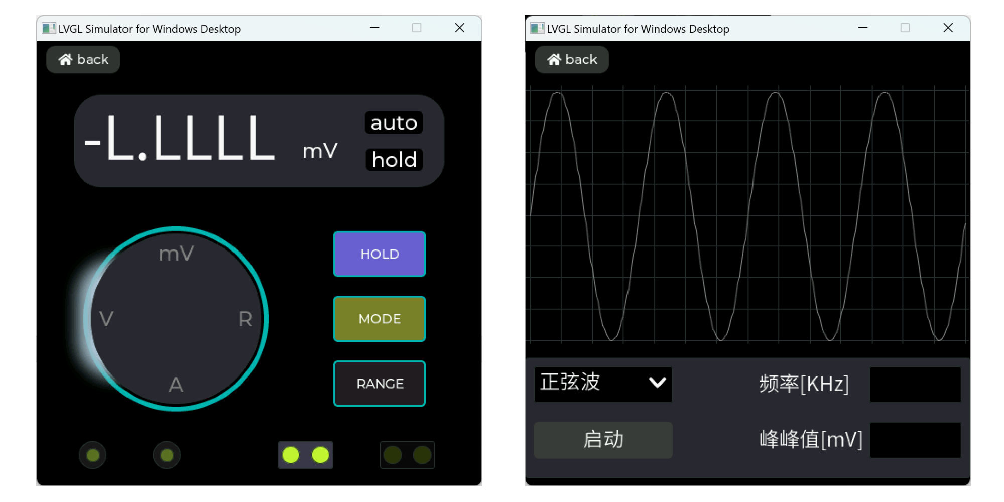
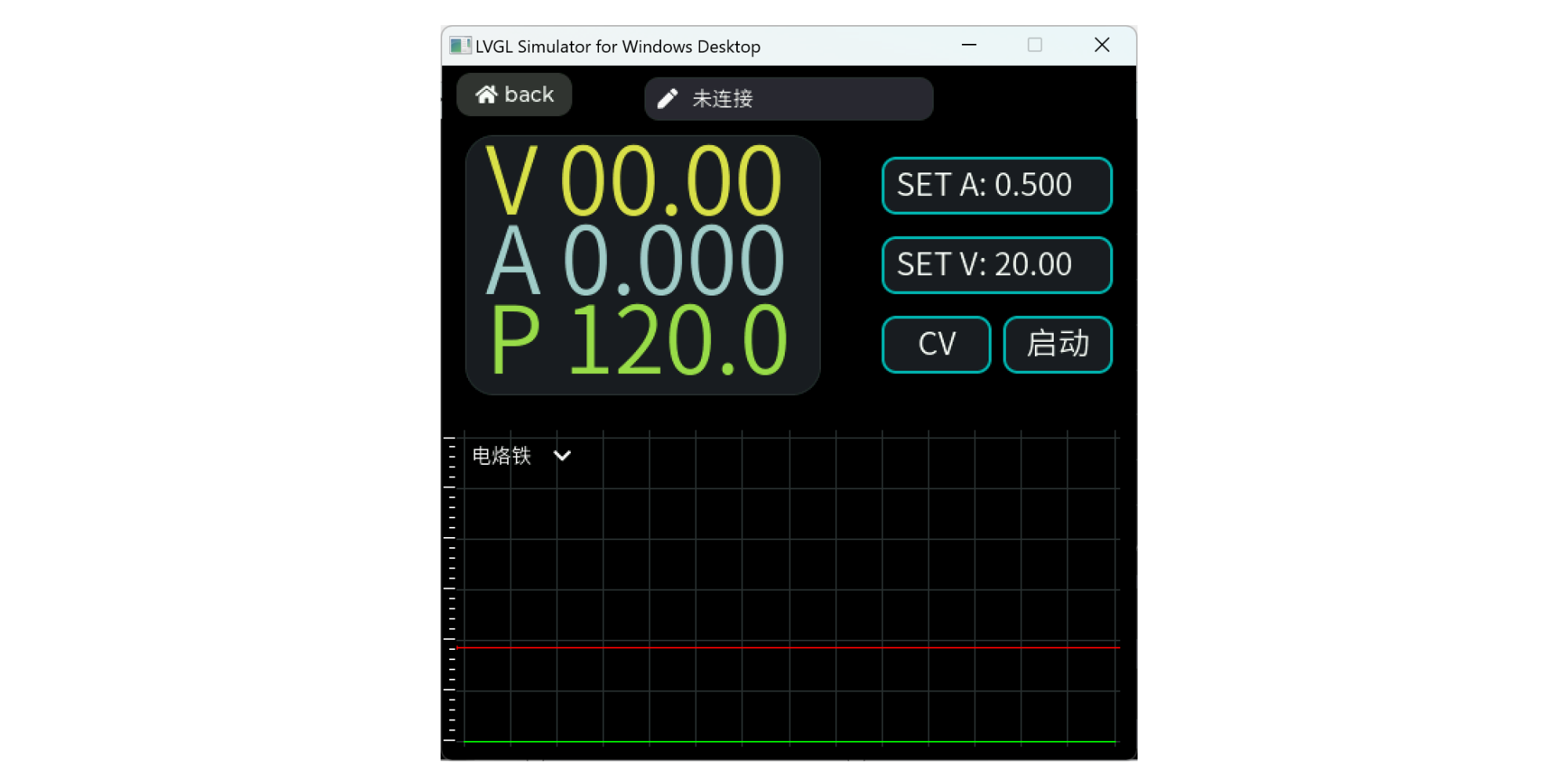
2.1.2 The app
currently only has 4 applications designed: soldering station, oscilloscope, multimeter, and signal generator. The interfaces of each application are as follows:
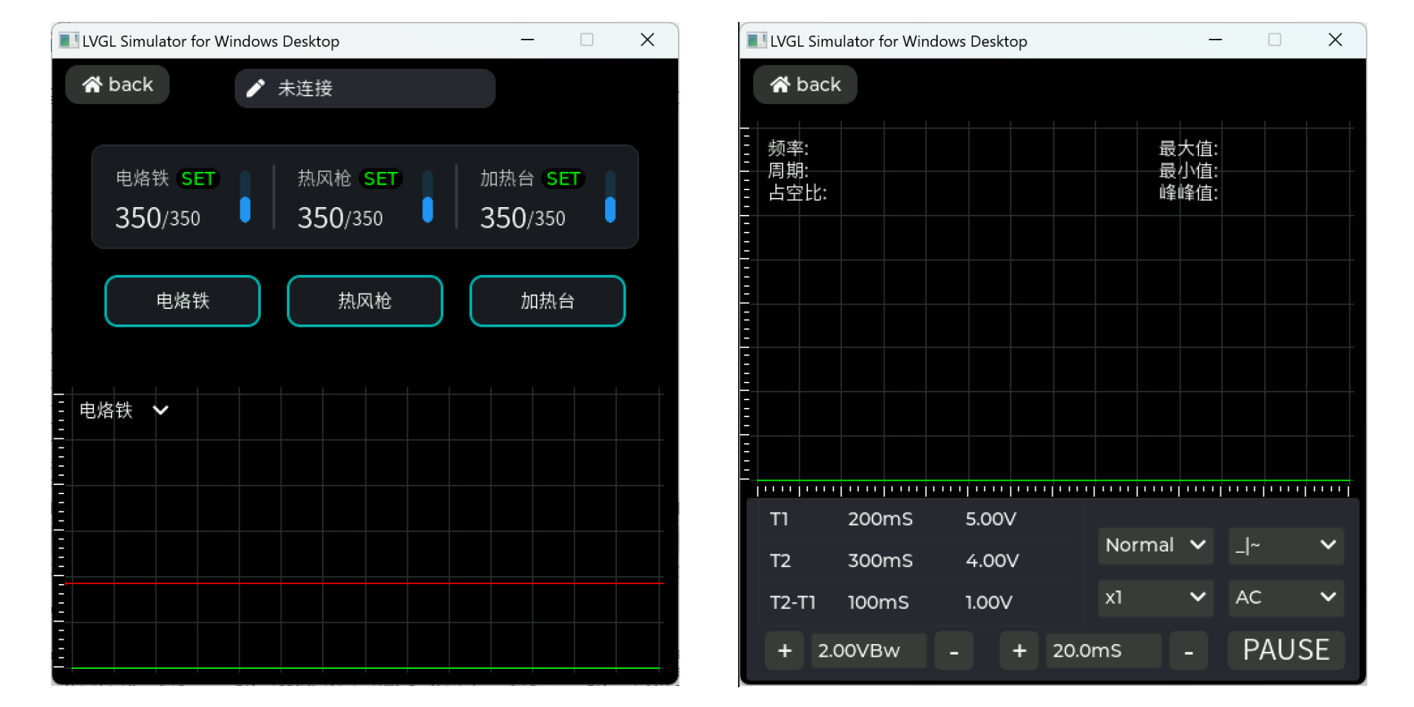
The soldering station application can only be operated effectively after the soldering station is connected. When the application is first entered, it displays some parameter status of heating devices such as soldering irons. Swiping left will take you to the CNC power supply interface. Other operations can be viewed in the attached test video.
2.2 Layered Design Framework
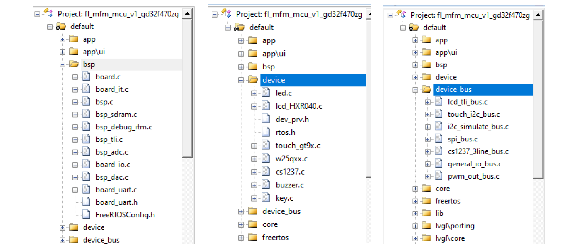
In order to improve the maintainability, reusability, and stability of the code, we need to design the code architecture in layers. Reusability here does not mean copying a piece of code to another application, but rather not modifying the entire source file. For example, we will basically not modify the basic library provided by the official website. A source file can only guarantee the maximum stability when it is not modified. In the design, we follow the principle of low coupling and high cohesion. Calls should be made from the upper layer to the lower layer as much as possible, and cross-layer calls should be avoided. Of course, in the actual writing process, the complexity should also be considered, and the excessive layering should not make the code more cumbersome. Here, I've divided the entire project into the application layer, board-level layer, middleware layer, device layer, and MCU driver layer. The device layer is further divided into the device application layer and the device driver layer. For ease of viewing, some layers in the diagram are not hierarchical; for example, the device application layer and middleware layer call each other.
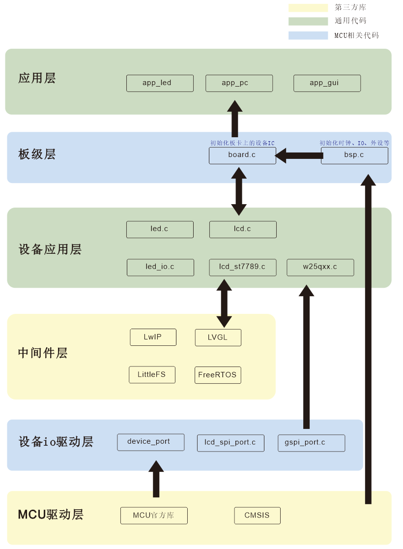
Based on reusability, I've categorized these layers into three parts: the middleware layer and MCU driver layer belong to third-party libraries; the application layer and device application layer do not depend on specific hardware; and the board-level layer and device I/O driver layer depend on specific hardware and boards. If the MCU or peripherals change, generally only the device I/O driver layer and board-level layer need to be replaced.
A device can be divided into hardware-related drivers and application drivers. The hardware-related driver part can be separated out; this part is related to the specific MCU driver. For example, in the CS1237 driver, hardware-related functions are designed as a structure:
`typedef struct
{
void (*init)(void *base);
void (*clock)(void *base, uint16_t time);
void (*set_dir)(void *base, uint8_t dir);
void (*write_bit)(void *base, uint8_t bit); uint8_t (
*read_bit)(void *base);
void (*int_enable)(void *base, uint8_t enable);
}cs1237_bus_t;
` Within the `cs1234_t` structure, a `cs1237_bus_t` pointer and a `void *` handle pointer are declared. Before use, the corresponding driver can be bound. This way, the device application code doesn't need to worry about the specific hardware implementation. If the MCU is changed, only a new `cs1237_bus.c` implementation of the functions within `cs1237_bus_t` needs to be written.
typedef struct
{
void *bus_handle;
cs1237_bus_t *bus;
CS1237_REG reg;
uint8_t initial;
int32_t data;
}cs1237_t;
//--board.c, void board_init(void)
cs1237_handle.io_clk.port = hal_port(PB, 3);
cs1237_handle.io_in.port = hal_port(PB, 4);
cs1237_handle.io_out.port = hal_port(PB, 5);
cs1237_handle.irqn = EXTI4_IRQn;
dev_connect(&board.adc_dev, &cs1237_handle, &cs1237_3line_bus);
cs1237_init(&board.adc_dev, kCS1237_SPEED_40Hz, kCS1237_PGA_1);
3.1 The instruction
manual is equipped with three buttons: power button, up button, and down button. Press the power button to turn on the meter, and click the interface icon to enter the application. Press the power button for 3 seconds to bring up the shutdown interface, where you can select "Shut Down" or "Restart". In the multimeter application, pressing the button will reset the meter to zero. See the attached video for detailed usage.
【All-in-One Soldering Station】
Project Introduction
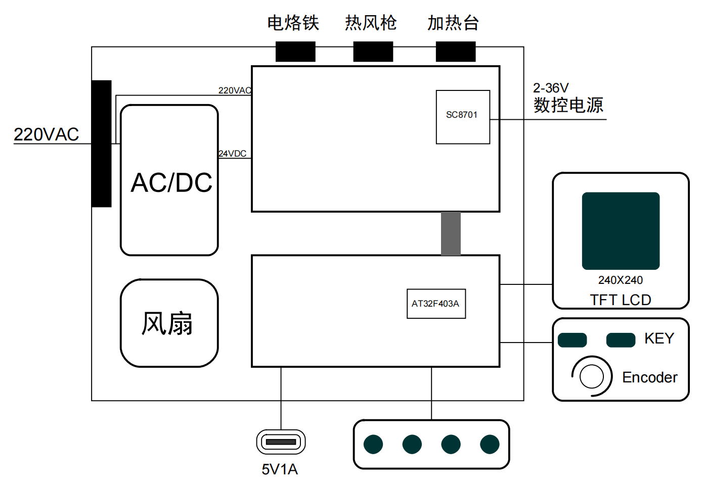
The soldering station integrates four functions: soldering iron (T12|JBC210|JBC245), hot air gun, heating table, and CNC power supply. It uses 220VAC power supply and has a built-in 200W switching power supply. The soldering iron and hot air gun are connected via an aviation connector, and the heating table is connected via an XT30PW(2+2)-M interface. The CNC power supply is connected via a 3mm banana plug. The overall structure is vertical and comes with an easily replaceable base. The overall dimensions are 92mm x 52mm x 132mm (length x width x height).
Project Parameters
and Interaction Method: 1.54-inch TFT LCD screen, 240x240 resolution, 3 tactile switches, 4 illuminated buttons.
Power Input Interface: Three-prong plug [220VAC].
Power Output Interface: Banana socket (adjustable power output), Type-C socket (5V1A output).
Temperature Control Interface: 5-pin aviation connector (soldering iron), 8-pin aviation connector (hot air gun), XT30PW(2+2)-M (heating station).
Adjustable Power Output Range: 1-36V, 0-7A.
1. Hardware
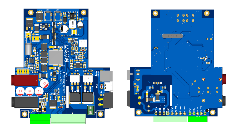
Soldering Station: There are two PCB boards, which I will refer to as the display board and the power board. The main controller uses AT32F403ARGT7, and the CNC power control IC uses SC8701. The circuit principle is relatively simple and is basically based on previous designs, and there are also many open-source projects available. Here, I mainly integrate these circuits and then make some new structural designs to make the internal structure compact and the wiring simple. The 3D diagram of the PCB board is as follows:

1.1 Frame
: Because 24VDC and 220VAC power supplies are required, a 200+W switching power supply is built-in. PD power supply is not used here. The power supply was purchased as a ready-made product; the link on Taobao (no advertising): 24V8A9A225W Wide Voltage Switching Power Supply Board PFC+LLC Medical Industrial Control Voltage Stabilizer Module H225S24.
This was chosen mainly due to power and size considerations. The same store also has a 180W power supply with compatible size; this option can be chosen if you are not using a soldering iron while simultaneously turning on the CNC power supply for high-power output.
1.2 Structure:
As this is a Spark project, I still prefer CNC for the casing. Mounting the switching power supply on the side also facilitates heat dissipation. The base was 3D printed with resin (because the panel has a Bluetooth chip, which will be developed later). The top cover is made of acrylic material.
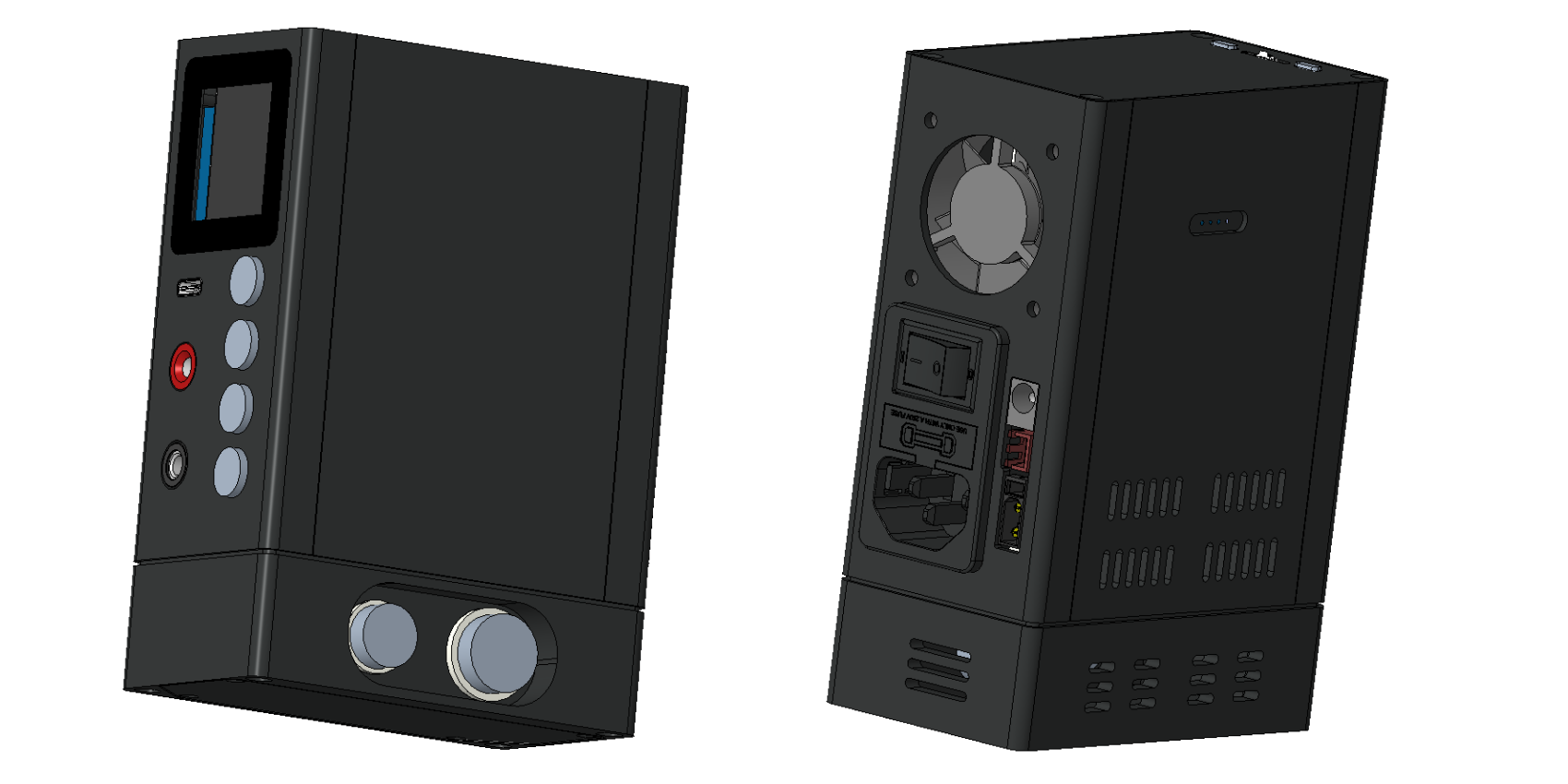
The overall structure is vertical. To make efficient use of internal space, all interfaces are led out through the front, back, and bottom sides. All interfaces are on-board plug-in, thus saving internal wiring.
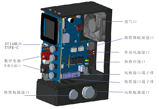
The base primarily serves for fixation, counterweight, and interface conversion. As shown in the image above, the soldering iron and hot air gun interfaces are actually led out through the 3.5mm pitch terminal block on the board, and then converted to the aviation connector inside the base. You can design the base according to your personal preferences, moving the aviation connector to other sides, or directly using the terminal plugs on the board, which can reduce the height of the base.

Soldering Iron Connector Definition
| Pin | Definition |
| --- | --- |
| 1 | Heating V- |
| 2 | ID | |
3 | Sleep |
| 4 | Temperature Sensing temp |
| 5 | Heating V+ |
Hot Air Gun Connector Definition
| Pin | Definition |
| --- | --- |
| 1 | Temperature Sensing temp+ |
| 2 | Temperature Sensing gnd |
| 3 | Fan+ |
| 4 | Fan- |
| 5 | Magnetic Control sleep |
| 6 | Heating L |
| 7 | Heating N |
| 8 | Ground EGND |
1.3 Principle Analysis
1.3.1 Power Supply Design
The power supply to the power board has two paths: 24VDC and 220VAC. The 24VDC is used to power the entire circuit board and the outputs of several fans and the soldering iron. The 220VAC is used for the outputs of the heating table and the hot air gun. The 24V power supply is connected through the soldered terminals on the board. The internal design shows that the power lines are very close together from the switching power supply to the board terminals. However, there's a design flaw: VCC and GND cross.

There's also a pair of 220VAC power lines that need to be connected to the switching power supply, so there are only six wires required internally.

The image above shows the power board's power circuitry. U7 is a TVS diode placed at the power input to suppress transient overvoltages. Q6 is a PMOS transistor for reverse connection protection; when the power is connected correctly, the VGS biased MOS is turned on, and it's turned off when reversed. This effectively reduces power consumption compared to using diodes directly. Since the input voltage is known not to exceed 27V, a Zener diode is not added to prevent damage from excessive MOS gate voltage. U6 is a step-down DC-DC chip that can continuously output 3.5A of current, converting 24VDC to 5V to power the entire core, output through an external Type-C port, and charge a touchscreen multifunction meter via a magnetic connector. The maximum charging current is 1A, with the Type-C output limited to 1A, and the remaining capacity used for the internal core.
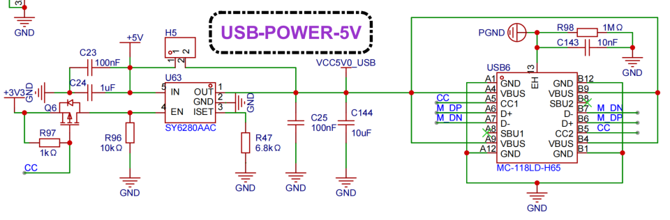
The 5V power supply is connected to the panel via an FPC flexible cable, and then output to the Type-C port via the SY6280AAC. When an external powered device is detected, Q6 conducts to enable the output. R47 is used for output current limiting, $Ia=6800/R47$.
1.3.2 PWM Output
A separate section on PWM is written because this project uses a large number of PWM IO pins. PWM stands for Pulse-Width Modulation, which is a periodic square wave with key parameters including frequency and duty cycle. In the AT32F403A, pins labeled TMRX_CHX can be used as PWM outputs, but you need to be careful about conflicts with other peripherals. For example, if the SPI4 peripheral is enabled and multiplexed as SPI4_GMUX_0010, then PB6 will be multiplexed as SPI4_CS and cannot be used as TMR4_CH1. Also, when you use multiple channels in the same timer to output PWM, their frequencies point to the same register.
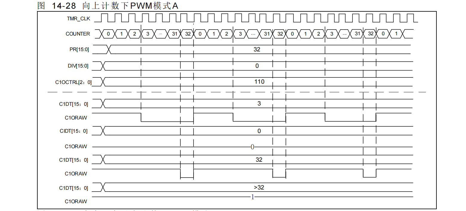
Most commonly used ARM core MCUs have two PWM output modes (A and B) and two counting methods (up and down). Different PWM output logics can be designed by combining these modes. Here, I'm using mode A (up counting), which outputs a high level when CXDTT > CVAL, and a low level otherwise. During use, you'll find that the PWM output isn't completely off or on when the duty cycle is 0 or 100%. This is due to the selected mode and internal logic. You can check in the code whether the duty cycle is 0 or 100 and set the I/O pin to normal GPIO mode to output a high or low level. Alternatively, you can use the forced output mode of the AT32F403A to directly set the corresponding register to output high or low levels.

PWM is a common function in timers, and there are many other interesting uses such as encoder mode and input capture; you can refer to the corresponding user manual for details. In this project, PWM is used to drive a buzzer, LED, analog DAC, and MOSFETs.
For driving LEDs
, we generally use the I/O port directly. The design logic is such that the LED lights up when the I/O output is 0, and turns off when it's 0. To change the brightness of an LED, you can drive it using PWM. Adjusting the PWM duty cycle controls the power output, and at a certain frequency, the human eye perceives the change in LED brightness. If the duty cycle is periodically changed from low to high and then back to low, it creates the common breathing light pattern. Compared to simple on/off behavior, PWM-controlled LEDs can represent more parameters, such as the output duty cycle of a soldering iron, temperature, etc. The board has three PWM-controlled LEDs corresponding to the soldering iron, hot air gun, and heating pad. The
buzzer
board uses a surface-mount external driver, requiring a PWM-driven transistor to drive the buzzer. Refer to the manual; it's typically 4kHz. Changing the frequency adjusts the buzzer tone, and changing the duty cycle adjusts the volume. For
analog DAC outputs
, when you need to output a single analog signal with extremely low frequency changes, you can use the PWM I/O pins. The PWM signal is converted to a more precise amplitude PWM signal, then passed through a second-order low-pass filter. The output signal is equivalent to a certain analog quantity, and then a follower is used to reduce the output impedance.
The MOSFET is driven
by PWM to control the output power. It's important to ensure that the VGS voltage does not exceed the MOSFET's operating voltage. In the diagram, R2 and R6 divide the voltage to keep Q1's VGS around 13V.
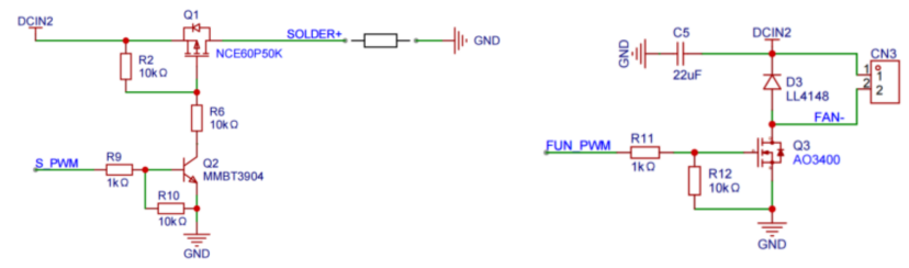
The temperature of the soldering iron, hot air gun, and heating plate is collected by converting the temperature into a small voltage signal via a thermocouple, then amplifying this signal through an operational amplifier circuit before feeding it into the MCU's ADC pin for sampling. Note that if using a T12 soldering iron, its temperature sensing element is connected in series with the heating element. Heating must be stopped and the signal stabilized before sampling. D1 is also needed to limit the 24V voltage input to the operational amplifier during heating. An

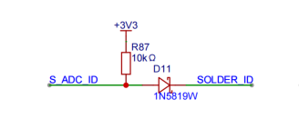
ID pin is added to the soldering iron wiring to detect the soldering iron type. Different resistors can be connected to different types of soldering iron handles, and the MCU identifies the soldering iron by sampling the voltage on the ID pin.
1.3.4
The principle of the CNC power supply is similar to the previous mini CNC power supply project, so it will not be discussed in detail here. Compared to the previous version, the output feedback resistor and capacitor voltage rating have been modified, increasing the output upper limit to 36V.
1.3.5 The heating circuit
is as shown above.
2.
As is customary, the software used here is FreeRTOS+LVGL, the IDE is Keil 5.38, and the host computer tools are written in Qt 5.14.1.
2.1 GUI Design:
See the [Multi-Function Tables] section.
2.2 Layered Design Framework:
See the [Multi-Function Tables] section.
2.3 PID Control Adjustment
: PID control calculates a new control value based on the system error using proportional (P), integral (I), and derivative (D), and then performs control. The control value is updated periodically by calculating the error value. Heating devices generally use incremental PID, which means that the required increase in control quantity is calculated based on the error value each time and added to the previous control quantity.
Formula: $Δu =
There are many online resources for Kp((e0-e1)+Kie0+Kd(e0-2e1+e2)$. I recommend watching this uploader's video tutorial, which explains PID from scratch in great detail.
If you, like me, are not very familiar with calculating PID parameters, then adjust them step by step according to the actual situation. I wrote a host computer software to view the real-time waveform, various error values, and PID value adjustments. First, set the I and D values to 0 and only set the P value, adjusting it until it is close to the set value and does not drift upwards. You will then see that the actual temperature may be lower than the target value. The following image shows the temperature waveform when P=30, I=0, D=0.
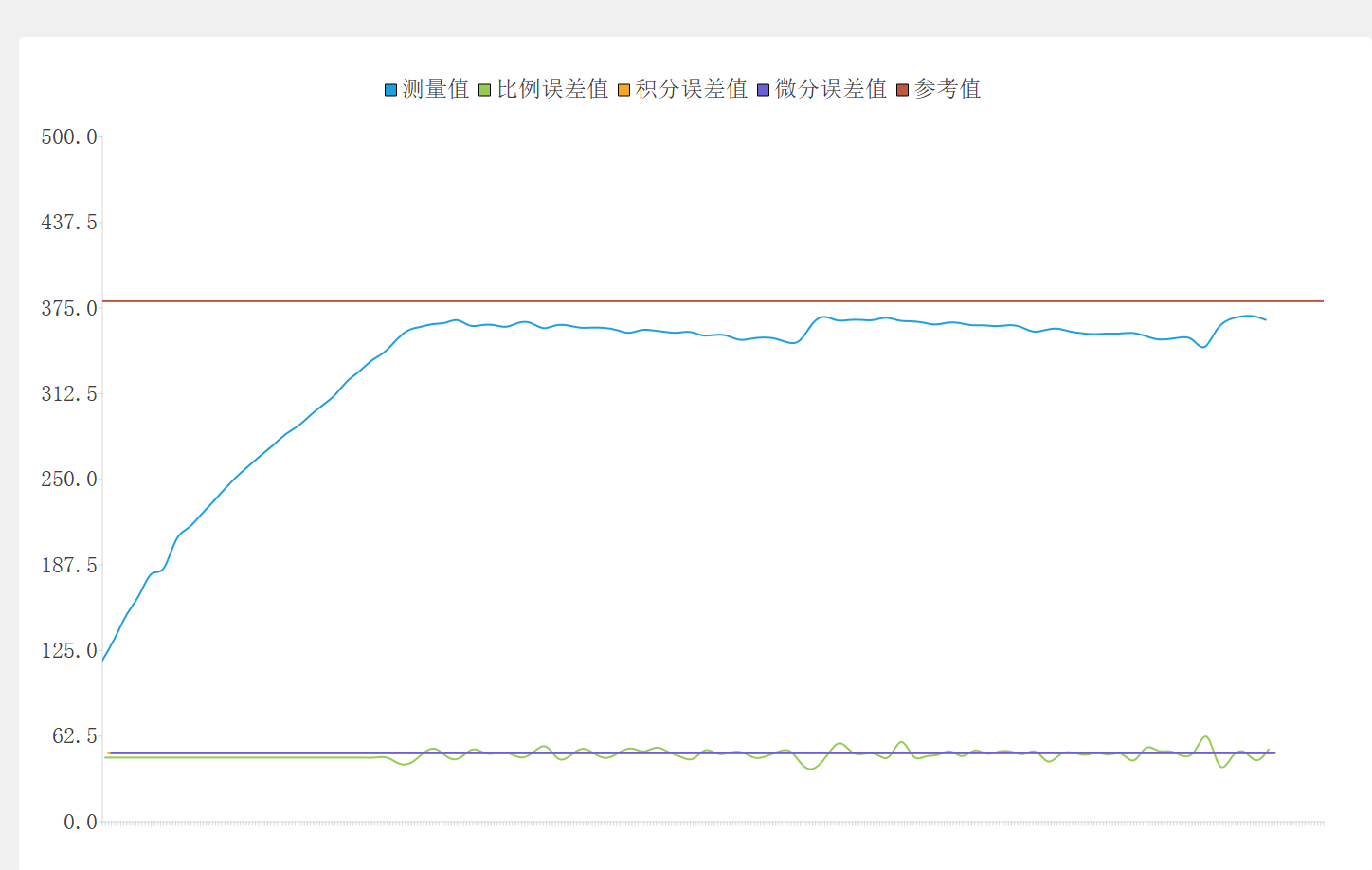
Adjust the I value to eliminate steady-state error and stabilize it to the target value, then slightly increase the D value. Cool it down again and then raise it up again to see if there is overshoot and whether it is acceptable. If not, slightly adjust the PID controller. The following image shows the temperature waveform when P=30, I=0.015, D=0.05.

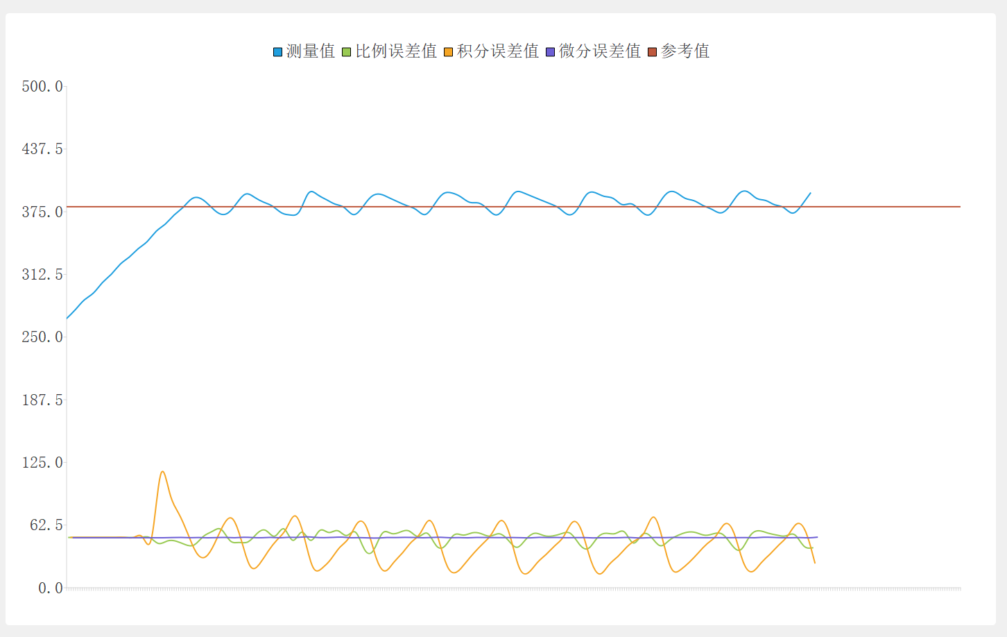
When the waveform is unstable, refer to the waveforms of the error values for each channel. The following image shows the temperature waveform when P=30, I=0.008, D=0.05.
2.4 FreeRTOS Tasks
FreeRTOS is a commonly used embedded operating system. As a lightweight operating system, it includes basic functions such as task scheduling, time management, memory management, and semaphore passing. Most MCUs currently have sufficient clock speeds and ROMs to run FreeRTOS.
I created several tasks, with the GUI task having the lowest priority, using idle time to refresh the GUI.

Additionally, the output control for the soldering iron and hot air gun is placed in an interrupt, which will be explained later.
Event groups are used in the code to trigger events. Tasks waiting for events are suspended, and the scheduler runs other tasks to avoid wasting time. For example, in the Task_Comm task, we can wait for the serial port data reception completion event to occur before proceeding to the next step.
void task_comm(void * para)
{
int32_t received = 0;
int32_t result;
commApplyInit(&commApply, tx_master_data);
commApply.send = task_comm_send;
while(1)
{
board_uart_IdleReceive(0, rx_master_data, 280, &received, pdMS_TO_TICKS(50));
if(received>0) //process data
{
result = protocol_decode(&commApply, rx_master_data, received);
}
}
}
The task calls the board_uart_IdleReceive() function, which calls xEventGroupWaitBits() to wait for the event to occur, and the event is set in the serial port interrupt function.
int board_uart_IdleReceive(uint8_t com_num, uint8_t *buffer, uint32_t length, int32_t *received, TickType_t xTicksToWait)
{
EventBits_t ev;
uint32_t bytesCurrentReceived = 0;
board_uart_handle_t *handle = &board.serial[com_num];
if (NULL == handle->base)
{
*received = 0;
/* Invalid handle. */
return kHalStatus_Fail;
}
ev = xEventGroupWaitBits(handle->rxEvent, RTOS_UART_IDLELINE, pdTRUE, pdFALSE, xTicksToWait);
if(ev&RTOS_UART_IDLELINE)
{
bytesCurrentReceived = ring_buff_read(&handle->rx_ring_buff, buffer, length);
if (bytesCurrentReceived > 0)
{
*received = bytesCurrentReceived;
return kHalStatus_Success;
}
}
*received = 0;
return kHalStatus_Fail;
}
2.5 The ADC acquisition
project requires acquiring multiple ADC channels. I use sequential mode for single sampling, software-triggered, meaning that each manual trigger performs a sequential acquisition and then stops. Because the T12 soldering iron needs to shut down its output before acquiring the temperature ADC, using a wait-and-go approach would waste MCU time. Therefore, I use TIM4 and DMA in conjunction. When the TIM4_OC4 counter overflows, the soldering iron is shut down; when TIM4 overflows and interrupts, the ADC is enabled; when the DMA transfer completes and interrupts, it indicates that the ADC acquisition is finished, and the relevant calculation functions can be called. Timers are not used to trigger the ADC because all triggerable timers are used for PWM output. The logic sequence diagram is as follows:
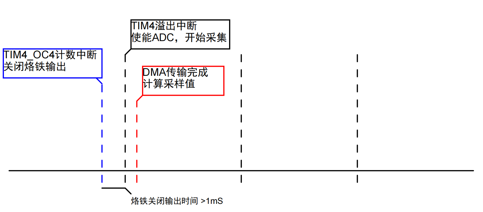
This interrupt method can save as much MCU time as possible, which can then be used for other tasks.
void TMR4_GLOBAL_IRQHandler(void)
{
if(tmr_interrupt_flag_get(TMR4, TMR_C4_FLAG) != RESET)
{
/* clear tmr2 channel1 interrupt pending bit */
tmr_flag_clear(TMR4, TMR_C4_FLAG);
board_pwm_out(kBoardPWM_Solder, 0);//Turn off the power of the soldering iron
}
else if(tmr_interrupt_flag_get(TMR4, TMR_OVF_FLAG) != RESET)
{
/* clear tmr2 channel1 interrupt pending bit */
tmr_flag_clear(TMR4, TMR_OVF_FLAG);
adc_ordinary_software_trigger_enable(ADC1, TRUE);//Start ADC sampling
}
}
//ADC DMA
void DMA1_Channel1_IRQHandler(void)
{
if(dma_interrupt_flag_get(DMA1_FDT1_FLAG) != RESET)
{
dma_flag_clear(DMA1_FDT1_FLAG);
board_pwm_out(kBoardPWM_Solder, app_dev.out.solder.value);//Restore soldering iron PWM output
task_solder(10);
task_gun(10);
device_wave_cnt();
}
2.6
Simulating EEPROM
Some data needs to be retained even after power failure, which is usually done using an external EEPROM or flash memory. If the amount of data to be stored is relatively small and the erasure and write operations are not particularly frequent, we can simulate a portion of the MCU's internal flash memory as an EEPROM. Generally, we take the last segment of the flash memory for simulation. The reading code is relatively simple; we just need to read the pointer to the absolute address.
void board_memory_read(uint32_t read_addr, uint8_t *p_buffer, uint16_t num_read)
{
uint16_t i;
for(i = 0; i < num_read; i++) {
p_buffer[i] = *(uint8_t*)(read_addr+BOARD_EEPROM_BASE);
read_addr++;
}
}
When erasing or writing, the flash memory needs to be unlocked first, and then the segment containing the address needs to be read. If it is 0xff, it can be written directly; otherwise, it needs to be erased first and then written.
hal_status_t board_memory_write(uint32_t write_addr, uint8_t *p_buffer, uint16_t num_write)
{
uint32_t offset_addr;
uint32_t sector_position;
uint16_t sector_offset;
uint16_t sector_remain;
uint16_t i;
flash_status_type status = FLASH_OPERATE_DONE;
flash_unlock();
offset_addr = write_addr;
sector_position = offset_addr / BSP_FLASH_SECTOR_SIZE;
sector_offset = offset_addr % BSP_FLASH_SECTOR_SIZE;
sector_remain = BSP_FLASH_SECTOR_SIZE - sector_offset;
if(num_write <= sector_remain)
sector_remain = num_write;
while(1)
{
board_memory_read(sector_position * BSP_FLASH_SECTOR_SIZE, flash_buf, BSP_FLASH_SECTOR_SIZE);
for(i = 0; i < sector_remain; i++)
{
if(flash_buf[sector_offset + i] != 0xFF)
break;
}
if(i < sector_remain)
{
/* wait for operation to be completed */
status = flash_operation_wait_for(ERASE_TIMEOUT);
if((status == FLASH_PROGRAM_ERROR) || (status == FLASH_EPP_ERROR))
flash_flag_clear(FLASH_PRGMERR_FLAG | FLASH_EPPERR_FLAG);
else if(status == FLASH_OPERATE_TIMEOUT)
return kHalStatus_Fail;
status = flash_sector_erase(sector_position * BSP_FLASH_SECTOR_SIZE + BOARD_EEPROM_BASE);
if(status != FLASH_OPERATE_DONE)
return kHalStatus_Fail;
for(i = 0; i < sector_remain; i++)
{
flash_buf[i + sector_offset] = p_buffer[i];
}
if(memory_write_nocheck(sector_position * BSP_FLASH_SECTOR_SIZE, flash_buf, BSP_FLASH_SECTOR_SIZE) != kHalStatus_Success)
return kHalStatus_Fail;
}
else
{
if(memory_write_nocheck(write_addr, p_buffer, sector_remain) != kHalStatus_Success)
return kHalStatus_Fail;
}
if(num_write == sector_remain)
break;
else
{
sector_position++;
sector_offset = 0;
p_buffer += sector_remain;
write_addr += sector_remain;
num_write -= sector_remain;
if(num_write > BSP_FLASH_SECTOR_SIZE)
sector_remain = BSP_FLASH_SECTOR_SIZE;
else
sector_remain = num_write;
}
}
flash_lock();
return kHalStatus_Success;
}
2.7 Host Computer Software
I wrote a host computer software using Qt, mainly used for setting parameters and calibration, and can also read measured values and draw real-time waveforms.
Currently, the host computer communicates via serial port. The front of the soldering station has a Type-C port to provide 5V 1A power. I reused this Type-C port and used a virtual serial port via USB in the MCU side code to communicate with the host computer. Then I defined a custom communication protocol for sending and receiving data, so that other devices that use this communication protocol can also directly use this host computer software.
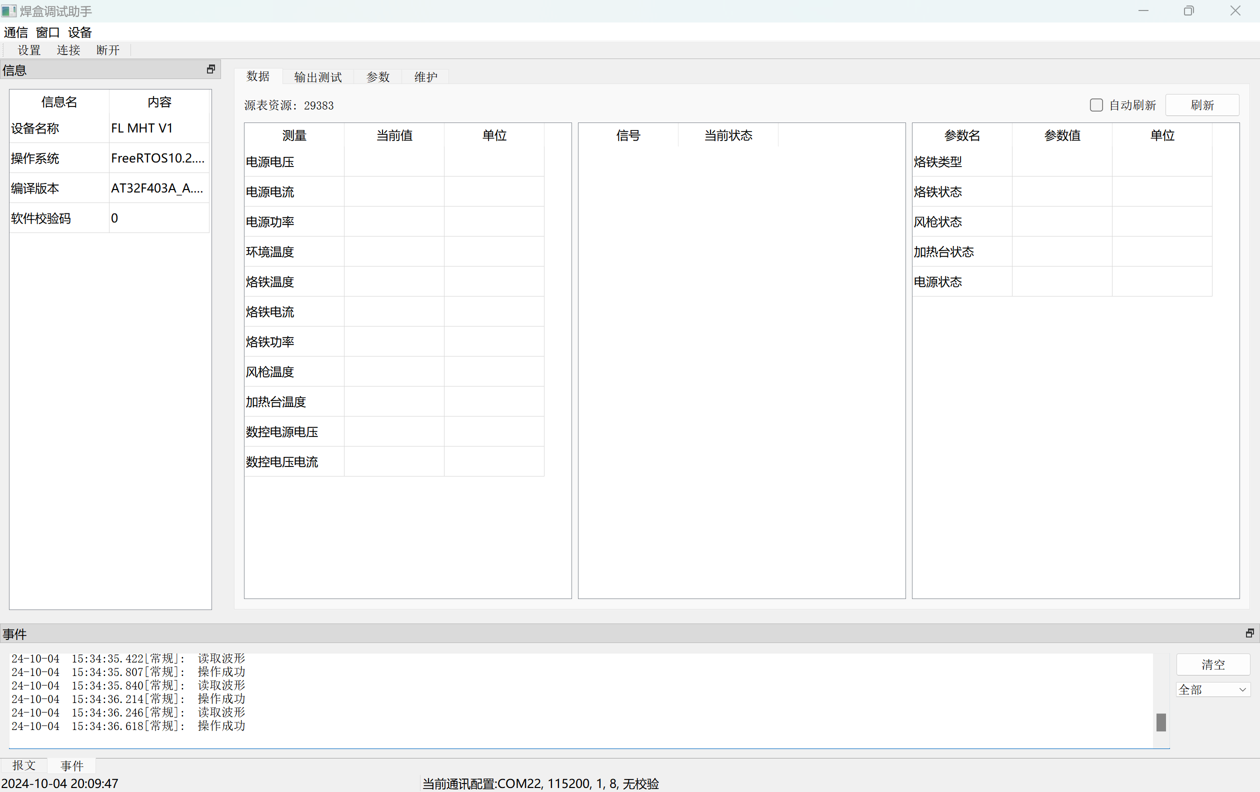
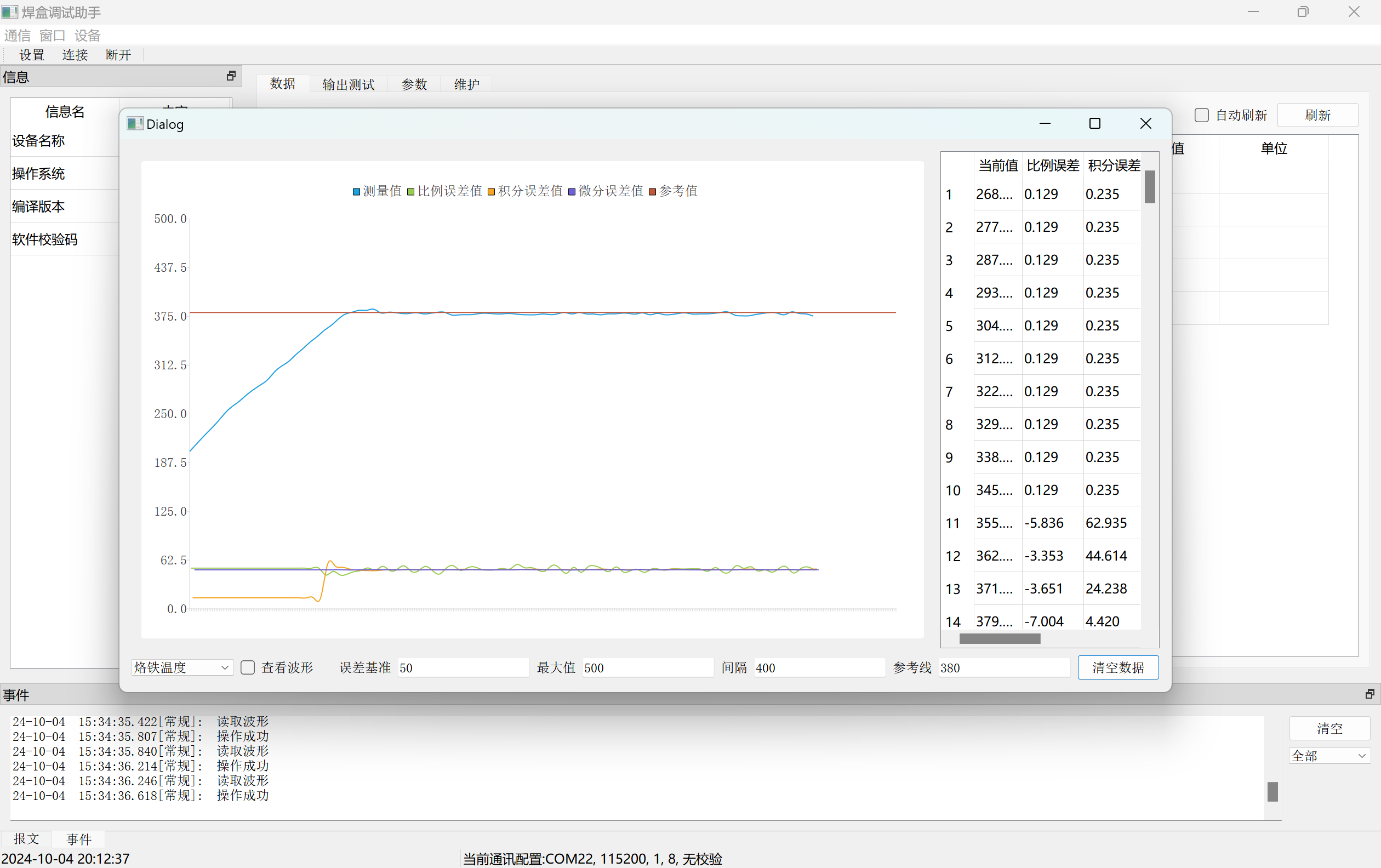
After selecting the serial port number, click "Connect" to proceed with subsequent operations. Below are the waveform and calibration interfaces.

The host computer software also provides complete source code, but I'm not particularly proficient in C++, and the writing style leans towards procedural programming. If there are many interested students, I can write a more detailed user manual.

3.1 Instructions for Use
The soldering station has four illuminated buttons, corresponding to the soldering iron, hot air gun, heating platform, and CNC power supply. Click once to activate the corresponding function, and click again to deactivate it. The soldering station retains a rotary switch and buttons for individual parameter settings, but I haven't written the code for this. Currently, I attach the multi-function meter to the soldering station and operate it using the soldering station app.

Project References
The project referenced the following materials; many thanks to the following authors! I may have forgotten some of them; if you see them, please send me a private message to add them. Thank you again!
Open source author Hardwood Classroom AFE03 Oscilloscope Signal Source Expansion Board
open source author zyqsdv 【LCSC*Liangshanpai】Portable Multifunctional Oscilloscope/Instrument open
source author LCSC Development Board 【Oscilloscope Expansion Board】
CSDN blogger PegasusYu STM32 Configuration for Reading Dual-Channel 24-bit Analog-to-Digital Converter (24-bit ADC) Chip CS1238 Data
Bilibili UP Equiangular Helix PID Zero-Based Introduction Tutorial
Others
The first version had some hardware issues, so I did some wire bonding myself. The second version has been released but not yet board-tested. Those who want to replicate it can try to build the V2 version!
The main code will be updated and submitted to Gitee. The project will be maintained irregularly.
Open source code: https://gitee.com/yllff/fl_aio_welding_station
QQ discussion group: 334607120


 京公网安备 11010802033920号

 177-714-5-25GP4K5-24FDG


