I. Design Background
An ADC (Analog-to-Digital Converter) is an indispensable key component in electronic systems. It converts continuous analog signals into digital signals, enabling digital processing and analysis. ADCs play a crucial role in signal conversion, measurement and data acquisition, control system input, and communication and signal processing. Their widespread application promotes the intelligent and precise control of electronic equipment across various industries, and is one of the key factors driving modern technological progress.
Digital voltmeters and ammeters combine ADC technology with circuit measurement principles, accurately converting analog voltage and current signals into digital displays for easy reading and analysis by electronic engineers. This device not only improves the accuracy and efficiency of circuit measurements but also helps engineers better understand circuit behavior, serving as a powerful tool for electronic design and troubleshooting, and playing a vital supporting role in the work of electronic engineers. In product applications, digital voltmeters ensure the accuracy and safety of circuit design, while also providing strong support for product quality control and subsequent maintenance.
II. Hardware Design
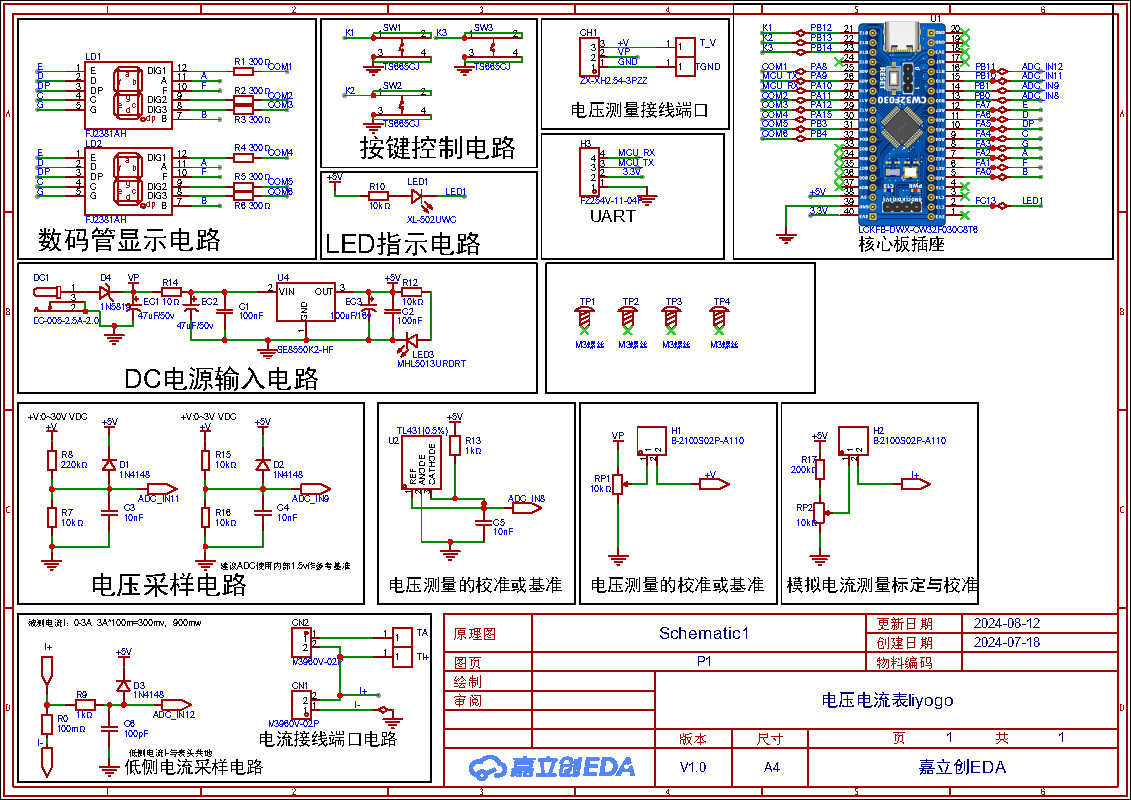
1. Schematic Diagram
An LDO (Low Dropout Linear Regulator) is used as the power supply. Considering that most voltmeter products are used in industrial scenarios with 24V or 36V power supplies, this project selected the SE8550K2 with a maximum input voltage of up to 40V as the power supply. The main reason for not using a DC-DC step-down circuit to handle the large voltage drop is to avoid introducing DC-DC ripple interference during the design process; a secondary reason is to reduce project costs.
The voltage divider resistor in this project is designed to be 220K + 10K, therefore the voltage division ratio is 22:1 (ADC_IN11).
is designed to measure the maximum voltage value. For safety reasons, this project uses 30V (the actual maximum display can be 99.9V or 100V).
The ADC reference voltage is 1.5V in this project, and this reference voltage can be configured through the program.
To reduce the power consumption of the sampling circuit, the low-side resistor (R7) is usually chosen as 10K based on experience.
Then, the high-side resistance of the voltage divider resistor can be calculated using the above parameters.
The required voltage division ratio is calculated, i.e., the ADC reference voltage. The input voltage is designed; using known parameters, 1.5V/30V = 0.05 can be calculated.
The high-side resistance is calculated as the low-side resistance/voltage division ratio; using known parameters, 10K/0.05 = 200K can be calculated.
A standard resistor is selected: a resistor slightly higher than the calculated value of 200K is chosen. We usually choose E24 series resistors; therefore, in this project, 220K, which is greater than 200K and closest to the calculated value, is selected.
If, in actual use, the voltage to be measured is lower than 2/3 of the module's design voltage (66V), the voltage divider resistor can be replaced and the program modified to improve measurement accuracy. The following example illustrates this:
Assuming the measured voltage is no higher than 24V and other parameters remain unchanged,
calculations show 1.5V/24V = 0.0625, 10K/0.0625 = 160K. 160K is a standard E24 resistor and can be directly selected, or a higher value 180K can be chosen with some redundancy.
If, in actual use, the voltage to be measured is higher than the module's 99V design voltage, a different resistor can be selected. To achieve a wider voltage measurement range, one can choose to replace the voltage divider resistor or modify the reference voltage. The following example illustrates this:
Assuming the measured voltage is 160V, the solution is to increase the voltage reference to expand the range.
Given that the voltage division ratio of the selected resistor is 0.0145, we can calculate 160V * 0.0145 = 2.32V using the formula. Therefore, we can choose a 2.5V voltage reference to achieve the increased range (increasing the range will reduce accuracy).
Considering the potential fluctuations in the measured power supply, a 10nF filter capacitor is connected in parallel with the low-side voltage divider resistor to improve measurement stability.
uses digital tubes as the display unit.
Two 0.28-inch three-digit common-cathode digital tubes are used as the display devices. Compared to a display screen, digital tubes have better visibility in complex environments. Depending on the actual usage environment, smaller current-limiting resistors can be used to achieve higher brightness. Furthermore, digital tubes have better mechanical properties and are not as easily damaged by external forces as display screens. They are widely used in industrial and other applications requiring stable and reliable operation. From a development learning perspective, it's easier to learn electronic measurement principles and related development in a more targeted way.
In this project, after actual testing, the current-limiting resistors (R1~R6) of the digital tube were configured to 300Ω. The corresponding brightness, whether for red or blue digital tubes, showed good legibility and was soft and not glaring.
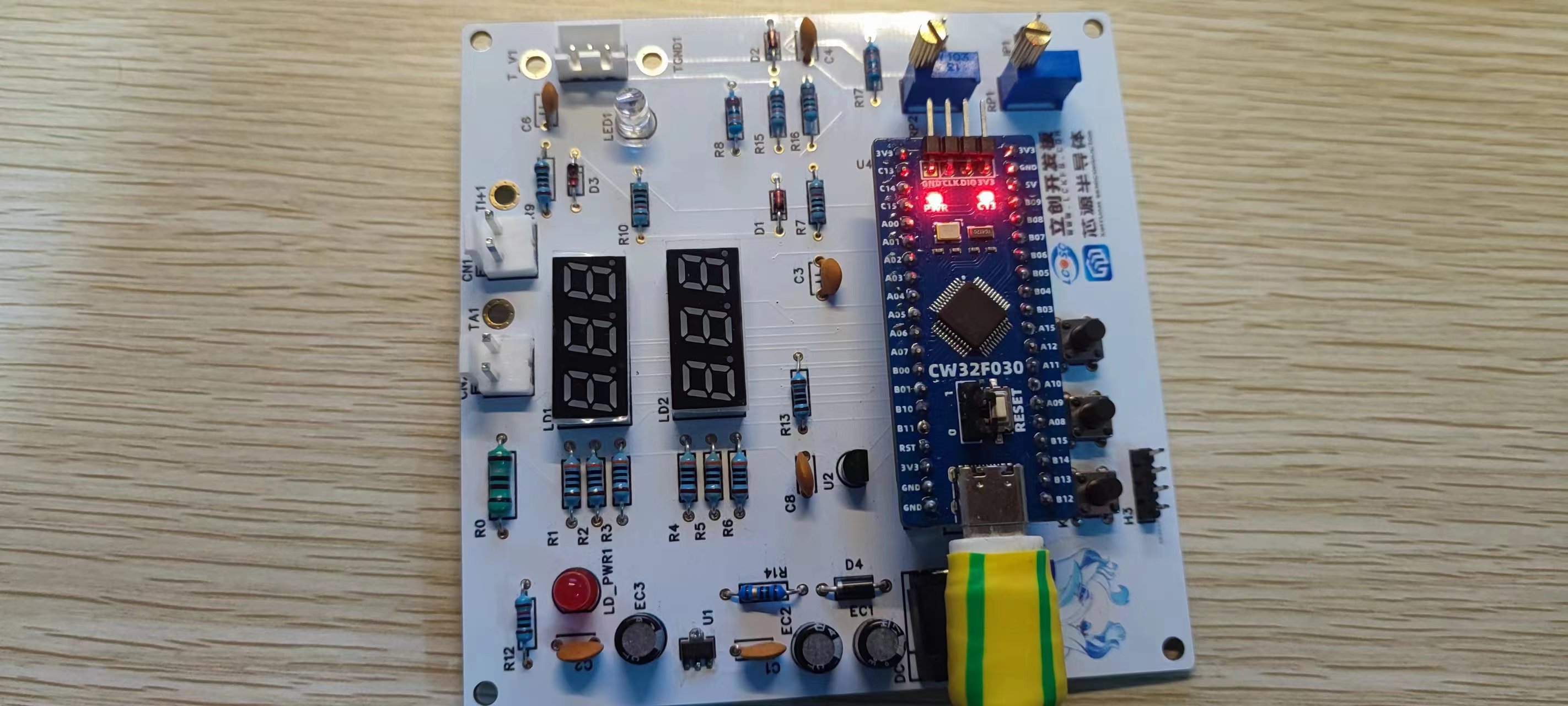
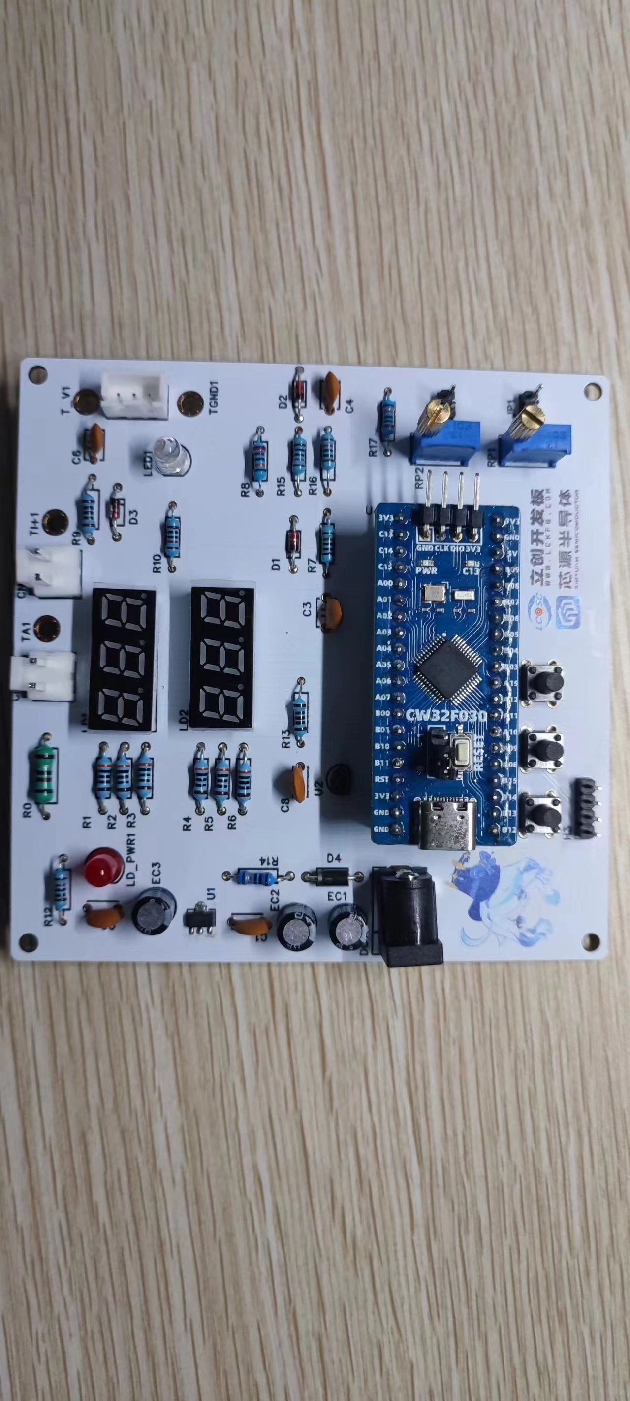
2. Physical Image
An ADC (Analog-to-Digital Converter) is an indispensable key component in electronic systems. It converts continuous analog signals into digital signals, enabling digital processing and analysis. ADCs play a crucial role in signal conversion, measurement and data acquisition, control system input, and communication and signal processing. Their widespread application promotes the intelligent and precise control of electronic equipment across various industries, and is one of the key factors driving modern technological progress. A digital voltmeter and
ammeter
combines ADC technology with circuit measurement principles, accurately converting analog voltage and current signals into digital displays for easy reading and analysis by electronic engineers. This device not only improves the accuracy and efficiency of circuit measurements but also helps engineers better understand circuit behavior, making it a powerful tool for electronic design and troubleshooting, and playing a vital supporting role in the work of electronic engineers. In product applications, digital voltmeters ensure the accuracy and safety of circuit design, while also providing strong support for product quality control and subsequent maintenance.
Learning to design and build a digital voltmeter and ammeter is highly beneficial for improving one's professional skills. This digital voltmeter and ammeter project covers multiple aspects, including microcontroller circuit design and implementation, signal acquisition and processing circuit design, user interface development and optimization, and product appearance design. It integrates knowledge from multiple fields such as electronics, microcontroller programming, circuit design, and industrial design. Considering the learning pace and knowledge absorption capacity of beginners, we have specially launched this introductory-level digital voltmeter and ammeter project, which is very suitable for beginners in electronics and those who want to learn more about microcontroller applications. This project has the following highlights:
it adopts a core board plus expansion board design concept and uses plug-in components, making learning simpler and exploration more in-depth;
the core board uses the domestic Wuhan Xinyuan Semiconductor CW32 as the main controller, while also being compatible with other similar development boards; however, the CW32 has advantages.
The project is highly comprehensive and practical, and after completion, it can be used as a desktop instrument;
the project has abundant learning materials, including circuit design tutorials, PCB design, code programming learning, and training for engineers' debugging skills.
II. Hardware Design
1. Power Supply Circuit
LDO (Low Dropout Linear Regulator) Selection
![image.png]
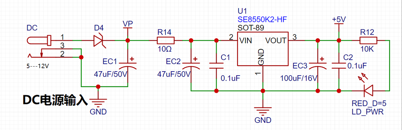
This project uses an LDO as the power supply. Considering that most voltmeter products are used in industrial scenarios with 24V or 36V power supplies, the SE8550K2 with a maximum input voltage of up to 40V was selected as the power supply. The main reason for not using a DC-DC step-down circuit to handle the large voltage drop is to avoid introducing DC-DC ripple interference during the design process, and the secondary reason is to reduce project costs.
Package Selection
From the table in the datasheet screenshot, it can be seen that compared with the 280℃/W of the SOT23 package, the 165℃/W of the SOT89 package has better heat dissipation capabilities (Thermal Resistance, Junction-to-Ambient).
The basic principle of almost all LDO devices is the same when designing circuits. Therefore, the reference significance of this diagram is not very high. What often differs is how C1 and C2 should be designed. If your LDO has EN (enable), you also need to consider the design of the enable pin to ensure that the chip works normally. In addition, some LDOs have adjustable outputs, which have a dedicated pin (adj) that requires the configuration of corresponding external resistors to achieve the specified output voltage.
The most crucial aspect of LDO peripheral circuit design is the capacitor design.
The capacitors surrounding the LDO play a critical role in the circuit, primarily in the following ways:
Filtering: The capacitors surrounding the LDO, especially the input capacitor, can effectively filter out ripple interference from the preceding power supply.
Improving load transient response: The output capacitor plays a vital role in improving load transient response. When the load current changes drastically, the LDO has an adjustment time. During this time, the output capacitor acts as a temporary power supply, providing the necessary current to the circuit and preventing the output voltage from being pulled too low. A larger output capacitor value can further improve the LDO's transient response to large load current changes.
Phase compensation: For adjustable output LDOs, the capacitor connected in parallel with the upper resistor (R1) (called the feedback capacitor CFB) provides leading phase compensation, increasing oscillation margin and improving load transient response. Returning CFB and R1 to zero contributes to loop stability.
Oscillation Prevention: Proper capacitor configuration helps prevent oscillations in LDO circuits, ensuring stable circuit operation.
Ripple Suppression: Capacitors in LDOs also help improve the power supply rejection ratio (PSRR), reducing the impact of power supply noise on circuit performance.
Startup Inrush Current Control: Input capacitors act as temporary power supplies for startup inrush currents during LDO startup, preventing the input voltage from being pulled down and affecting the stability of the preceding power supply.
Summary: Capacitors surrounding the LDO play important roles in filtering, improving load transient response, phase compensation, oscillation prevention, ripple suppression, and startup inrush current control. Proper configuration of these capacitors ensures the stability and performance of the LDO circuit.
If you carefully review the datasheet, you'll find detailed suggestions and references, as well as layout design recommendations. This avoids engineers performing complex theoretical calculations.
Figure 7
shows a notable use of electrolytic and ceramic capacitors in parallel, one after the other, in my power supply design. When electrolytic and ceramic capacitors are connected in parallel, they can be "high-low matched," resulting in good filtering performance in both high-frequency and low-frequency regions. Electrolytic capacitors filter low-frequency interference, while ceramic capacitors filter high-frequency interference; combining the two achieves better filtering results.
In practical electronic products, the main function of electrolytic capacitors in parallel with ceramic capacitors is to achieve high and low frequency filtering and coupling through their complementary characteristics, thereby improving circuit performance, stability, and anti-interference capabilities. This parallel connection method is widely used in electronic devices. For
reverse connection protection,
considering that high-voltage reverse connection can cause irreversible damage to the module, the voltmeter power supply circuit uses a series diode scheme for reverse connection protection.
Figure 8
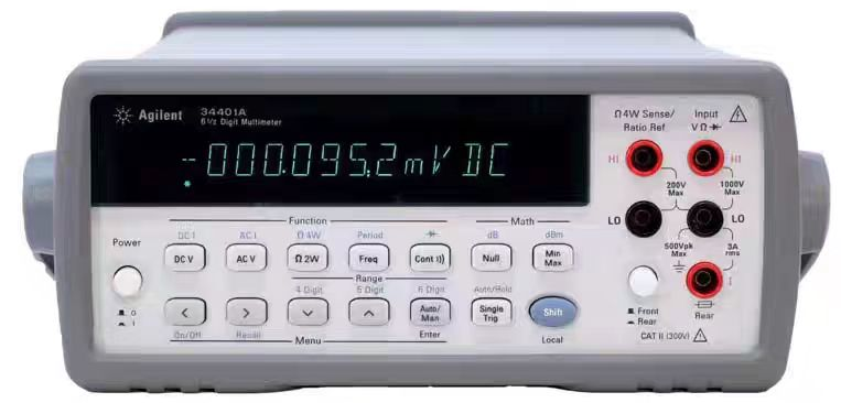
Note: This project uses a series diode for reverse connection protection because the power supply voltage of this device is usually higher than 5V, and the 0.7V voltage drop of the diode will not affect the power supply. When the power supply voltage is low, due to the low overall power consumption of the project, the measured power supply current is low (20mA). Due to the unique structure of the Schottky diode D4 (1N5819), compared with general switching diodes, its VF is lower; as shown in the figure below, the voltage drop is approximately within 0.2V.
In conventional circuit design, using a reverse parallel diode + series fuse can also achieve the purpose of reverse connection protection and circuit protection.
The additional use of a series small resistor (10Ω)
in this project for voltage division reduces the problem of excessive heat generation in the LDO due to the large voltage difference under high voltage conditions. Furthermore, it utilizes the principle that the series 10-ohm low-power resistor has low overcurrent, acting as a low-resistance fuse, providing overcurrent or short-circuit protection. (The reason the resistor acts as a fuse is that, under overcurrent and heating conditions, it is 99% open-circuit, and rarely short-circuit. Its fault analysis dictates that it is primarily an open circuit—that is, it burns out, not short-circuited.)
The series small resistor (10Ω) also reduces the peak value of the power-on surge, preventing excessive surges from damaging the LDO.
If electrolytic capacitors are not used, a small series resistor (10Ω) can also prevent resonance between the wire inductance and the ceramic capacitor during hot-plugging. Because ceramic capacitors have very low ESR, the damping in the LC network is minimal, resulting in high gain at the resonant point. Adding an external resistor to provide damping can suppress this gain.
Circuit design considerations and specifications
: When drawing power supply circuits, whether in schematics or PCB layouts, the following points should be noted:
Schematic specifications: GND should face down, power supply should face up; avoid ground facing up.
Capacitor design: In both schematics and PCB layouts, electrolytic capacitors should come first, followed by ceramic capacitors
. Grounding design: Single-point grounding; the ground of the current power supply should be connected to the GND of the main electrolytic capacitor of the current power supply, and the ground of the main electrolytic capacitors of each stage of the power supply should be connected to the GND of the main electrolytic capacitor of the preceding stage.
2.
Download
link for the MCU selection analysis section: https://pan.baidu.com/s/1erHWOS6Gej_82cJVNF_jdw?pwd=LCKF Extraction code: LCKF
To reduce the learning cost, this project uses the LCSC CW32F030C8T6 development board (core board) as the main controller, but this does not mean we will cover this section less. From the perspective of training engineers, the correct selection of the main controller is very important, as it relates to the overall advantage of the project.
Regarding the voltage and current meters, the author used STM32/CW32 and some other 32-bit microcontrollers for debugging and testing. Here, we only compare it with the STM32F103C8T6 as a reference for learning device selection, mainly to provide ideas and improve understanding.
Do not blindly select a model.
When selecting the MCU (microcontroller unit) for this project, multiple aspects need to be considered to ensure that the selected MCU meets the project requirements.
Clearly define your project requirements: Understand the required computing power, including clock speed, processor core type, and whether a floating-point unit is needed.
Identify the required I/O ports and important peripherals, such as the ADC. Since this is a development board project primarily for debugging and learning, there are no strict limitations on the number of I/O ports; cost considerations are not taken into account.
Key advantages of CW32 in this project
: Wide operating temperature range: -40~105℃;
Wide operating voltage range: 1.65V~5.5V (STM32 only supports 3.3V systems);
Strong anti-interference: HBM ESD 8KV; All ESD reliability meets the highest international standard (STM32 ESD 2KV).
Project focus - Better ADC: 12-bit high-speed ADC, achieving ±1.0LSB INL 11.3ENOB; Multiple Vref reference voltages... (STM32 only supports VDD=Vref);
Stable and reliable eFLASH technology. (Flash0 pending)
A detailed explanation of the advantages will be provided in the chapters on ADC sampling and related extensions.
The main characteristics of the CW32's ADC:
This project requires a focus on the 4 reference voltage sources. Content from the "CW32x030 User Manual,"
Figure 4.3
: Voltage Sampling Circuit.
This project uses a voltage divider circuit to achieve high-voltage acquisition, designed to acquire up to 100V; the current configuration acquires voltages from 0-30V.
Figure 5
shows that the voltage divider resistors in this project are 220K+10K, so the voltage division ratio is 22:1 (ADC_IN11).
The voltage divider resistor selection
is based on the maximum measured voltage. For safety reasons, this project uses 30V (the actual maximum can be 99.9V or 100V).
The ADC reference voltage in this project is 1.5V, which can be configured through the program.
To reduce the power consumption of the sampling circuit, the low-side resistor (R7) is usually selected as 10K based on experience.
Then, the high-side resistance of the voltage divider resistor can be calculated using the above parameters. The
required voltage division ratio is calculated as follows: ADC reference voltage: Design input voltage, which can be calculated using known parameters as 1.5V/30V=0.05.
The high-side resistance is calculated as: Low-side resistance/voltage division ratio, which can be calculated using known parameters as 10K/0.05=200K.
A standard resistor is selected: A resistor slightly higher than the calculated value is chosen. The calculated value is 200K. We usually choose E24 series resistors, therefore, in this project, we choose 220K, which is greater than 200K and closest to the calculated value.
If, in actual use, the voltage to be measured is lower than 2/3 of the module's design voltage (66V), the voltage divider resistor can be replaced and the program modified to improve measurement accuracy. The following example illustrates this:
Assuming the measured voltage is no higher than 24V and other parameters remain unchanged,
calculations show 1.5V/24V = 0.0625, 10K/0.0625 = 160K. 160K is a standard E24 resistor and can be directly selected, or a higher value 180K can be chosen with some redundancy.
If, in actual use, the voltage to be measured is higher than the module's 99V design voltage, a different resistor can be selected. To expand the voltage measurement range, you can choose to replace the voltage divider resistor or modify the reference voltage. Here's a case study:
Assuming the measured voltage is 160V, we can choose to increase the voltage reference to expand the range.
Given that the voltage division ratio of the selected resistor is 0.0145, we can calculate 160V * 0.0145 = 2.32V using the formula. Therefore, we can choose a 2.5V voltage reference to expand the range (increasing the range will reduce accuracy).
Considering the potential fluctuations in the measured power supply, a 10nF filter capacitor is connected in parallel with the low-side voltage divider resistor to improve measurement stability.
Diode clamping ensures MCU safety
. In designing this project, I added an additional 1N4148 (D1, etc.) as a clamping diode to the sampling circuit. This helps avoid damage to the chip pins due to incorrect voltage input during learning and debugging. Diode clamping is an important electronic circuit design technique; its main function is to protect the circuit by limiting the voltage amplitude, preventing damage or malfunction caused by excessively large or small signals.
In circuit design, clamping refers to limiting voltage. Diode clamping specifically refers to the technique of using a diode to limit the potential at a point in a circuit.
Diode clamping primarily utilizes the unidirectional conductivity of a diode. When the voltage across the positive terminal of the diode is greater than the voltage across the negative terminal and the diode is turned on, the voltage across the diode is limited to its voltage drop across the diode, typically around 0.7V for a silicon diode.
The clamping process involves forcibly pulling the clamped potential towards the reference terminal through the diode's clamping action, thus limiting the potential. Clamping does not change the waveform of the original signal; it only raises or lowers the reference potential.
Depending on the diode connection method, clamping circuits can be divided into positive clamping circuits and negative clamping circuits. This project only designs a positive clamping circuit.
A positive clamping circuit occurs when the positive terminal of the diode is grounded. During the positive half-cycle, the diode is cut off; during the negative half-cycle, the diode is turned on, and the capacitor is charged to a certain voltage, limiting the output voltage within a certain range.
Negative clamping circuit: When the negative terminal of the diode is grounded, it is a negative clamping circuit. Its working principle is the opposite of the positive clamping circuit.
Adding a voltage sampling circuit to achieve range switching:
In this project, an additional voltage sampling circuit was added. Therefore, we can discuss the significance of range switching for improving measurement accuracy. To achieve more accurate measurements, multimeters often have multiple range settings. By adjusting different ranges, the optimal measurement accuracy of the measured point within the corresponding range can be obtained.
This project requires a combination of hardware and software to implement this function. When we first use the ADC_IN11 channel mentioned earlier to measure voltages within 30V, if the measured voltage is within 0~3V, then we use the ADC_IN9 channel for measurement. At this time, due to the reduced voltage division ratio, the measurement accuracy is greatly improved.
There are many ways to implement range switching; the development board design provides more design possibilities. The circuit diagram
in Figure 6, used for simulating voltage measurement, calibration, and calibration assistance, is shown in Figure 7. The components labeled T_V and T_GND next to the voltage measurement terminals are 2mm banana plug connectors on the development board, used to connect multimeter probes. Multimeter or high-precision benchtop digital multimeter probes can be inserted to verify the accuracy of the development board's measurements. Alternatively, 2mm banana plug multimeter probes can be inserted to replace the CH1 port for handheld measurements. The VP pin is the development board's power supply pin and should not be connected when using the DC port. When not using DC port power and the measured value is greater than 5V and less than 30V, the power supply under test can be connected, or it can be powered independently. Considering that users may not be able to easily build external circuits for testing and debugging when learning the corresponding circuit measurement principles, and adhering to the principle of ease of development of the development board, a circuit for simulating voltage measurement, calibration, and calibration assistance is specifically included. No external voltage is required for CH1. Use a multi-turn adjustable potentiometer (RP1) to divide the power supply voltage of the development board and connect it to the +V network through the internal circuitry of the development board. Note that JP1 needs to be shorted at this time; a jumper cap is sufficient, and a long-handled jumper cap is recommended. Do not short JP1 if this function is not used. 4. Current Sampling Circuit: This project uses a low-side current sampling circuit for current detection. When the low-side of the sampling circuit shares a common ground with the development board's meter interface , do not solder R0!!! Figure 8 Design Analysis: The sampling current designed for this project is 3A, and the selected sampling resistor (R0) is 100mΩ. The following aspects need to be considered when selecting the sampling resistor: the maximum value of the pre-designed measurement current; the voltage difference caused by the 3A current sensing resistor in this project ; generally, it is not recommended to exceed 0.5V ; the power consumption of the current sensing resistor should be selected based on this parameter; considering the power consumption (temperature) issue under high current , a 1W packaged metal wire-wound resistor was selected ; the voltage amplification factor of the current sensing resistor: no operational amplifier was used to build the amplification circuit in this project, so the factor is 1. The current sensing resistor value can then be calculated using the above parameters. The project does not use an amplifier circuit, therefore a larger sampling resistor is needed to obtain a higher measured voltage for measurement. Considering that a larger resistor would result in a larger voltage drop and higher power consumption, an unlimited selection of a larger resistor is not feasible. This project uses a 1W package resistor, corresponding to a power consumption of 1W. Based on the above data, a 100mΩ current sensing resistor was chosen. According to the formula, 3A * 100mΩ = 300mV, 900mW. To handle different operating environments, especially high-current scenarios, the R0 resistor can be replaced with constantan wire or a shunt. The choice of alternative can be based on the specific application scenario. For safety and educational purposes, this project will not discuss measurements exceeding 3A, but the principle remains the same. The current sampling is connected in series to the circuit under test. Two interfaces are provided for debugging (i.e., development board learning requirements). For normal measurements, only CN1 needs to be connected. When a project requires connecting a multimeter or similar device in series for comparison and verification, pin 1 of CN2 (red wire - current in) and pin 2 of CN1 (black wire - current OUT) should be used simultaneously. As an aside: If using both terminals simultaneously seems too cumbersome, in the circuit design, please change the network of pin 2 of CN2 from I+ to GND. In this case, normal measurements still only require connecting to CN1, while when a project requires connecting a multimeter or similar device in series for comparison and verification, only CN2 needs to be connected. Figure 10 shows the auxiliary circuit for simulating current measurement, calibration, and verification. When using this function, do not solder the sampling resistor R0. If this function is not used, disconnect JP2. The essence of current sampling is to collect the voltage drop across the sampling resistor when current flows through it, i.e., to collect the voltage value. This circuit uses RP2 to provide a voltage value in the range of 0~0.238V (5V ÷ 210K * 10K), which is connected to the chip's current sampling pin via the I+ network. In actual use, the voltage at I+ simulates the voltage drop across the unsoldered 100mΩ sampling resistor. Therefore, the simulated measured current value I<sub>measured</sub> = this voltage value Vi+ ÷ 100mΩ, which is also exactly equal to the measured voltage value multiplied by 10. That is, it provides a simulated current measurement of 0~2.38A. Set a multimeter or high-precision benchtop digital multimeter to the voltage measurement port, with a range within 3V. Insert the black negative probe into the T_GND interface next to the voltage measurement terminal, and the red positive probe into the TI+ port for current measurement to measure the actual voltage value of I+. Thus, this circuit can not only complete the above design tasks but also allow for a direct test of the accuracy of the MCU's ADC peripheral. You can write your own program to verify this. 5. Digital Tube Driver: This project uses digital tubes as the display unit. Two 0.28-inch three-digit common-cathode digital tubes are used as display devices. Compared to displays, digital tubes have better visibility in complex environments. Depending on the actual usage environment, smaller current-limiting resistors can be used to achieve higher brightness. Furthermore, digital tubes have better mechanical properties and are not as easily damaged by external forces as displays. They are widely used in industrial applications requiring stability and reliability. From a development board learning perspective, this makes it easier to learn electronic measurement principles and related development in a targeted manner. In this project, actual testing showed that the current-limiting resistors (R1~R6) for the digital tubes were configured to 300Ω. The corresponding brightness, whether for red or blue digital tubes, had good visibility and a soft, non-glaring brightness. Strictly speaking, the current-limiting resistors should be added to the segments; adding them to the digits would affect the display effect. Our actual design places them in the digits to save a few resistors, but the impact on the display is not significant. Therefore, we add them to the digits for convenience. Let's calculate the current required for the digital tubes. This project actually uses dynamic scanning to drive the digital tubes, so at any given time, only a maximum of 8 segments of the digital tubes (or LEDs) can be lit, or in other words, only one digit can be lit. According to the design, the required driving current is approximately 11mA, which is the high-level voltage of the IO port: 3.3V ÷ 300Ω.
At this point, it's important to ensure the selected MCU has sufficient current-pull/sinking capability.
Figures 14
and 15
show that the CW32 has no issues (some chips are not suitable).
For the selection of the current-limiting resistor for the digital tube display
, the datasheet for the digital tube used can be found on the LCSC website. Generally, the parameters of similar digital tubes are roughly similar.
Figure 16
indicates that, according to the datasheet, the current-limiting resistor limits the maximum current to no more than 35mA DC forward current, and the drive voltage to be greater than 2.9V (current 20mA). We use a 300Ω current-limiting resistor to reduce the If current to 11mA. Since the CW32 and its core board can use a 5V system, the current will be 16mA. 300Ω is sufficient to ensure normal display. A smaller resistor would result in brighter display, and due to reduced current consumption, the LDO at the power supply terminal can also introduce a lower input voltage.
6. Indicator Lights
This project additionally designed a power indicator light and an IO operation indicator light.
Figure 17
shows the LD_PWR indicator light.
Figure 18
shows the IO indicator light.
Since chip I/O often has a greater sinking capacity than a pulling capacity, LED1 is designed to be active low (on). To reduce the current consumption of the LED, some LED brightness is sacrificed, and the number of device parameter types is reduced. The current-limiting resistor for the LED is chosen to be 10K.
Taking the plug-in F5 white-to-white (white light) LED used in this project as an example, the table below shows its electrical parameters. From the table parameters, it can be seen that the current-limiting resistor setting must ensure the current is within 20mA. (This can be calculated using Ohm's Law.)
Figure 19
explains several terms:
White-to-white LED: The first "white" refers to a white or transparent shell, emitting white light. There are also red-to-red and white-to-red LEDs, where white-to-red refers to a red LED with a white or transparent shell.
F5: φ5, the diameter of the LED shell is D=5mm. Most F3/F4/F5 LEDs on the market have the same pin spacing, P=100mil (2.54mm).
7. Button Circuit Design:
Figure 20
shows the button control circuit. There are multiple design methods. Thanks to the CW32's internal I/O ports which can be configured with pull-up and pull-down resistors, the button control circuit on the chip's periphery does not require configuration. One end of the button is connected to the MCU's I/O, and the other end is grounded. When the button is pressed, the I/O is pulled low.
8. TL431 Circuit Design for Voltage Measurement and Calibration:
This project adds an extra TL431 circuit to provide a 2.5V reference voltage. This can be used to provide an external voltage reference for calibrating the AD converter. From a product design perspective, due to the CW32's inherent ADC performance advantages, this circuit is not necessary. This circuit is designed on the development board for learning related application principles. [Image 1]
[ Image 2 ] [Image 3]


A simple evaluation board based on the Zeyao A28 module, which facilitates the connection of DuPont wires to the development board during normal use.
This is a simple evaluation board based on the Zeyao A28 module, facilitating the connection of DuPont wires to other development boards.
It can be used with development boards such as ESP32S3 and ESP32C3 to act as an ExpressLRS receiver or LNB!
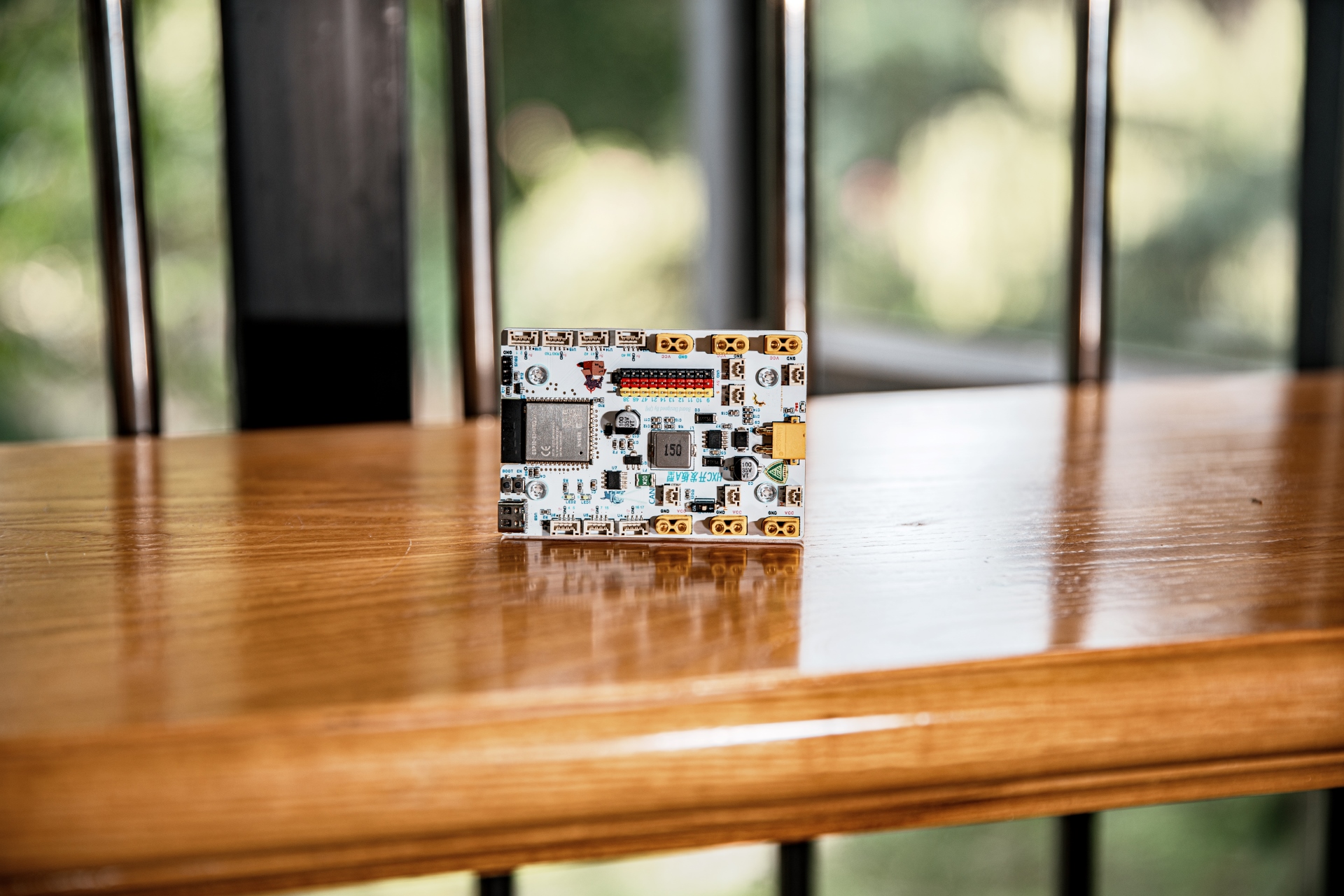
The Chongqing University of Posts and Telecommunications HXC team's robot development kit can replace the commonly used RM development board A-type
sample programs and libraries: https://github.com/CQUPTIMTA/BoardA
Last updated: August 25, 2024
Known Issues - Solutions:
Fuse easily blows and does not reset - Shorting the fuse pads
during the first programming session does not automatically enter download mode - Manually press boot to enter download mode. HXC Development Board Type A


Design Concept:
Although the DJI Type A development board boasts powerful performance and has been validated in competitions for many years, its high price, difficulty in repair, high learning curve, and long development cycle have always troubled us.
Therefore, we designed this development board using the ESP32 S3 as the main controller and utilizing as many low-cost and common components as possible, keeping the cost below 50 yuan while achieving 80% of the functionality.
One CAN channel (with transceiver chip),
maximum 26V power input (can be powered by TB48S battery),
maximum 5V 3A step-down output,
seven GH1.25-4P customizable interface types (configurable as UART, I2C, etc.)
, ten GPIO pin headers for direct-plugging servos,
two programmable LEDs,
one SBUS/DBUS interface (receiver interface),
six XT30/CAN motor interfaces
, 5V and 3.3V motor interfaces with fuses and TVS protection.
All components are located on the front for easy soldering.
Hole positions and dimensions are completely consistent with DJI development board A type. Sample programs and code repositories:
All code is based on ESP32ArduinoSDK. Most libraries are developed in C++, and most modules are encapsulated in a single .hpp file for easy calling.
We use the vscode + platformio environment for development. If you prefer, you can also use the Arduino IDE or ESP-IDF. Simply copy the .hpp file of the required module to the project directory.
See the README file in the repository for details.
Click to enter the GitHub code repository .
Currently, our hardware libraries include:
DJI 3508, 2006 motor,
Zhang Datou closed-loop stepper control,
Huaner Bus servo,
OPS-9 odometer,
SBUS/DBUS.
Only 4 lines of code are needed to control M3508, M2006, GM6020.

Hardware Overview:
Peripherals:
4*SPI,
3*UART (USB can be simulated additionally)
, 2*I2C
, 2*I2S
, 8*PWM,
20*ADC.
All peripherals can be mapped to any available pin.
Power Supply:
VCC is stepped down to 5V via TPS5430. 5V is stepped down to 3.3V via AMS1117.

CAN:
Because the ESP32 has a built-in CAN controller, we only added an external TJA1050 CAN transceiver chip.

Download Circuit:
ESP32 The S3 has a built-in USB interface, so no additional download circuit is needed. This USB port can be configured as a serial port and for JTAG use.

Note that
during the first download, you need to press BOOT before inserting the USB to enter download mode.
After the program is downloaded, sometimes you need to restart the microcontroller for it to work properly (press EN).
The SBUS/DBUS
standard level inversion circuit uses the common S8050 transistor

test points ,
bringing out the test points for most pins, facilitating jumper wires, multimeter troubleshooting, and repair.

The HXC development board D-type
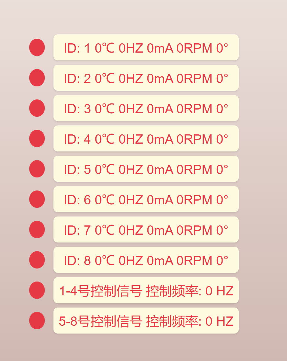
C3 minimum module has CAN transceiver and can be used as a main controller, CAN monitoring terminal, ESPnow receiver, etc., for functions such as
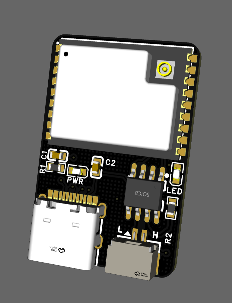
motor online detection ,
web-based online testing, and PID functionality. Once developed, it will be open-sourced.
The large power divider board
doesn't need much introduction;
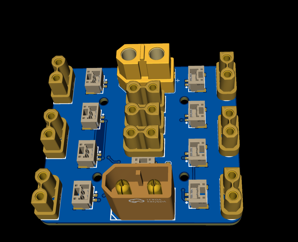
the small power divider board
is very compact.

The CAN transceiver module
can be used with ordinary ESP32.
A-plate outer casing.stp
HXC Development Board Type A BOM.xlsx
PDF_ESP32 Development Board Kit.zip
Altium_ESP32 Development Board Kit.zip
PADS_ESP32 Development Board Kit.zip
BOM_ESP32 Development Board Kit.xlsx
92588
CH340N serial port (verified)
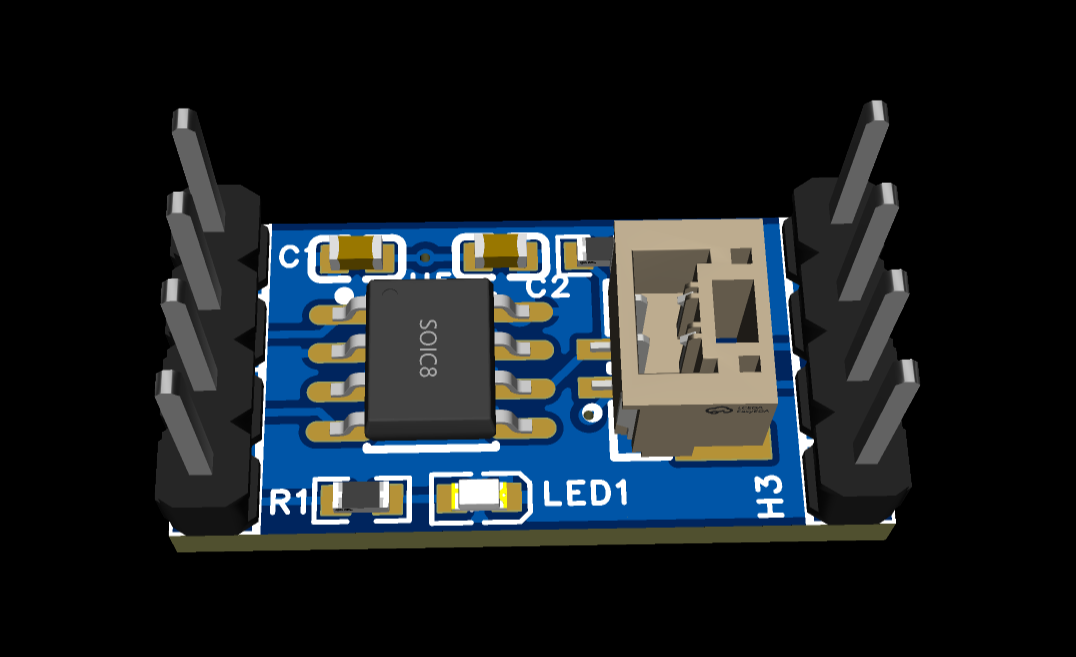
The CH340N is a small USB-to-TTL serial chip. I used the CH340N chip to build a USB-TTL serial communication module, realizing bidirectional communication between a USB interface and a TTL level device. This module is small in size and suitable for serial port debugging and microcontroller communication.
[d96b786361a2fcf4b5b3c7a5814a800.jpg]
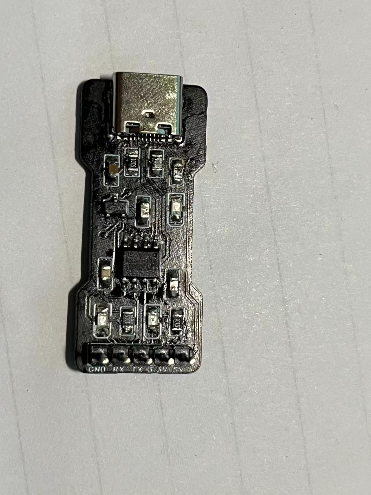
The RX pin of the CH340N connects to the TX pin of the microcontroller, and the TX pin of the module connects to the RX pin of the microcontroller. The silkscreen markings can be modified as needed.
PDF_CH340N Serial Port (Verified).zip
Altium_CH340N serial port (verified).zip
PADS_CH340N Serial Port (Verified).zip
BOM_CH340N Serial Port (Verified).xlsx
92589
TB6612 Four-channel Encoding Driver
TB6612 is a four-channel motor driver with 5V voltage regulation, a maximum current of 3A, and reverse connection and short circuit protection.
First version link:
https://oshwhub.com/fourteenzzh37/tb6612-four-way-coding-driver-bo

Project Introduction
Concept:
The TB6612FNG is a driver IC for DC motors, featuring a low on-resistance LD MOS structure output transistor. Through two input signals IN1 and IN2, one of four modes can be selected: clockwise (CW), counter-clockwise (CCW), short brake, and stop mode.
Characteristics
: Supply voltage: VM = 15V (maximum)
Output current: IOUT = 1.2A (average) / 3.2A (peak)
Low on-resistance output: 0.5Ω
Standby (power saving) System • Clockwise/Counter-clockwise/Short brake/Stop function modes
Built-in overheat shutdown circuit and low voltage detection circuit
Driver Circuit:
The TB6612 is a dual driver, capable of driving two motors; two onboard drivers allow for driving four motors, with additional power supply available. Truth table for
driving
PWM1A (connected to the microcontroller's PWM port)
:
AIN1 0 0 1
AIN2 0 1 0
Stop forward/reverse
A01
AO2 connects to two pins of motor 1. Truth table for
driving
PWM2B (connected to the microcontroller's PWM port)
:
BIN1 0 0 1
BIN2 0 1 0
Stop forward/reverse
B01
BO2 connects to two pins of motor 2.
The other two paths are similar.
The logic truth table
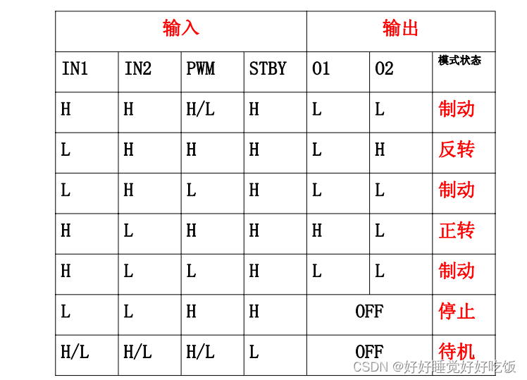
is as follows: When the STBY port is connected to the microcontroller's I/O port, clearing it stops all motors.
Project parameters and
usage functions: Timer output comparison, output PWM
. 1. Find the corresponding I/O pins according to the schematic diagram
. 2. Find the corresponding (timer and timer channel) in the chip datasheet (PWMA, B pins).
3. Enable the corresponding clock for the I/O port and the timer clock
. 4. Configure timer initialization: TIM_TimeBaseInit()
5. Configure the corresponding channel: TIM_OC3Init() / TIM_OC4Init()
6. Enable CRR preload channel register.
7. Enable ARR preload channel register.
8. Enable timer.
9. Set duty cycle (pass parameter value).
10. Control the motor according to the truth table.
11. Pass positive or negative parameters to control true reverse rotation of the motor.
First Edition.mp4
With short circuit protection and reverse connection protection.mp4
PDF_TB6612 Four-Channel Encoding Driver.zip
Altium_TB6612 Quad Encoding Driver.zip
PADS_TB6612 Four-channel Encoding Driver.zip
BOM_TB6612 Four-channel Encoding Driver.xlsx
92590
electronic
 1.1 Power Supply Circuit
 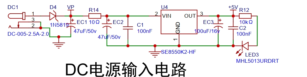 1.2 Voltage Sampling Circuit
 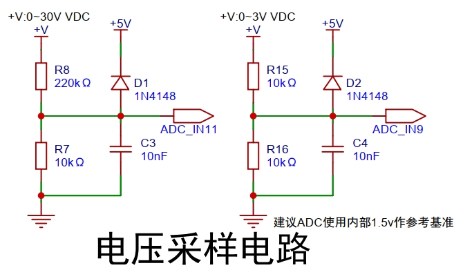 1.3 The display circuit
  2. Physical Image
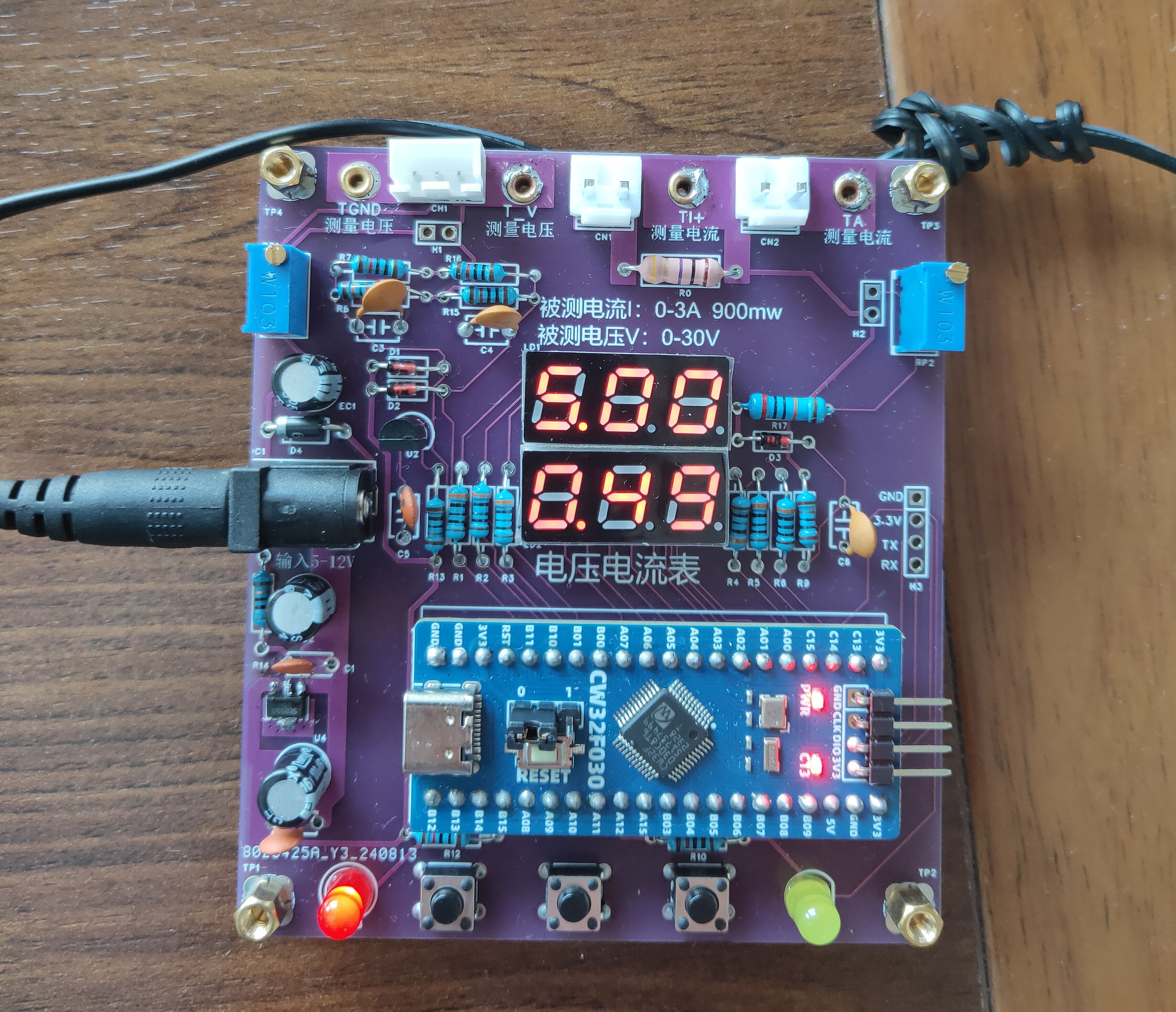


 京公网安备 11010802033920号

 RM242-070-211-8837


