Basic Function Introduction:
Low cost and ease of manufacturing are my constant pursuits. The wireless module uses the NRF24L01+, and a 433MHz module may be used in the future. The main chip is the STC8H8K64U-LQFP32.
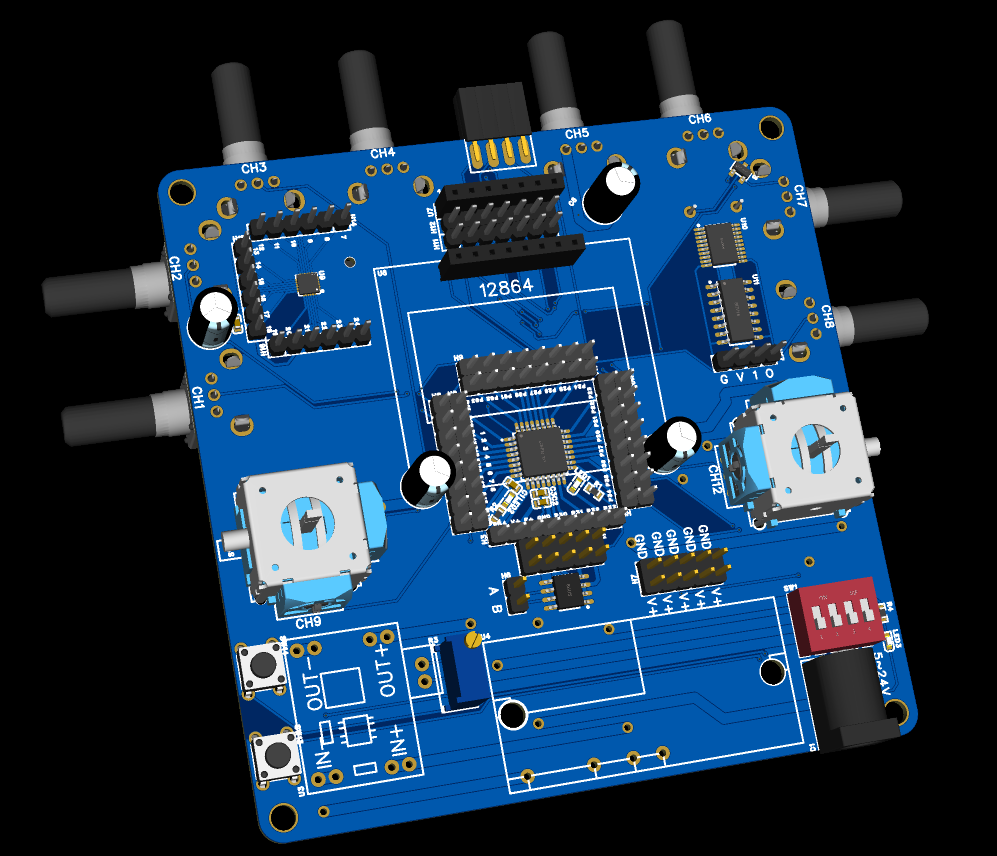
To
avoid the hassle of debugging after soldering, I isolated its pins from the outside; simply insert a jumper cap when using it. If you cut off the middle section, it becomes a simple STC8H8K64U-LQFP32 development board. Five power supplies are brought out for experimentation or powering expansion modules. The upper right corner is for downloading TP20 and SP16 microcontrollers; I've found that many students don't know how to download these microcontrollers. No soldering is required; simply press the microcontroller onto the package with tweezers to download. The upper left corner is an M540 gyroscope circuit, which can be used to learn about this type of gyroscope. Of course, these circuits do not need to be soldered; they are completely unrelated to the system. The bottom left corner contains a DC-DC step-down module, which needs manual modification. The original module's potentiometer adjustment was inconvenient, so I replaced it with an external potentiometer. If the voltage is frequently adjusted, this potentiometer should be replaced with one with a larger handle. However, a large handle is unsuitable for a remote control, as accidental contact could damage the chip. The upper middle section contains a 433 interface, which is not connected to the system; it's just for bringing out the module pins for easy DuPont wire insertion, primarily for experimental use. Since the main function of my remote control is to control vehicles, boats, and robotic arms, the distance requirement isn't very high, and I think the NRF24L01 should be sufficient. The lower middle section contains a voltmeter and ammeter, used to monitor whether the adjusted voltage is correct, and monitoring the current is sometimes necessary. This system can be powered by an external power supply below 5~24V or by a 3s battery. This is the first verification version, so errors are inevitable. I originally wanted to add other functions, but found the EDA automatic routing function unreliable, so I abandoned that idea. Time is running out, so I'll leave it as it is for now. If necessary, I'll modify it myself.
There's a MAX485 chip for transmitting data from the system to the host computer.
It also integrates an M540 gyroscope. I don't know how to use it yet. The schematic is terrible;
I wanted to improve it in the future, but it's difficult, mainly because my computer is too slow. Anyway, I doubt anyone will copy it, so I'll just leave it as it is. Just so I know it myself.
2024-7-12 PCB board arrived.
2024-7-13 Solder paste and flux arrived (I'm taking the kids out to play tomorrow, Sunday, so I can only start work on Monday night. I might be away on a business trip next week, so I don't know if I can finish).
2024-7-15 Discovered I could barely solder the 0402 package; I don't know how to use the solder paste, and the hot air gun soldering results are unsightly
. 2024-7-17 Started debugging the program (demonstration program; this board is for verifying whether various programs work) .
2024-7-19 All work is complete. Discovered the wrong battery box package was selected on the back of the PCB, so I had to abandon using the 18650.

Below is a picture after powering on (the screen has backlight, but I turned it off for the photo; see the 3mm gyroscope?).

# Important Disclaimer:
This verification board was only made for developing a remote control program. Although it can be used as a remote control, the program does not yet have the corresponding functions and can only be used as an example. This includes:
1. ADC
2. 24L01 transmission data
3. 12864 display


 京公网安备 11010802033920号

 MI-P722-MYZ


