Author: [Fabiano Riccardi](https://oshwlab.com/fabiano.riccardi) Original project link: [https://oshwlab.com/fabiano.riccardi/solar-charger](https://oshwlab.com/fabiano .riccardi/solar-charger)
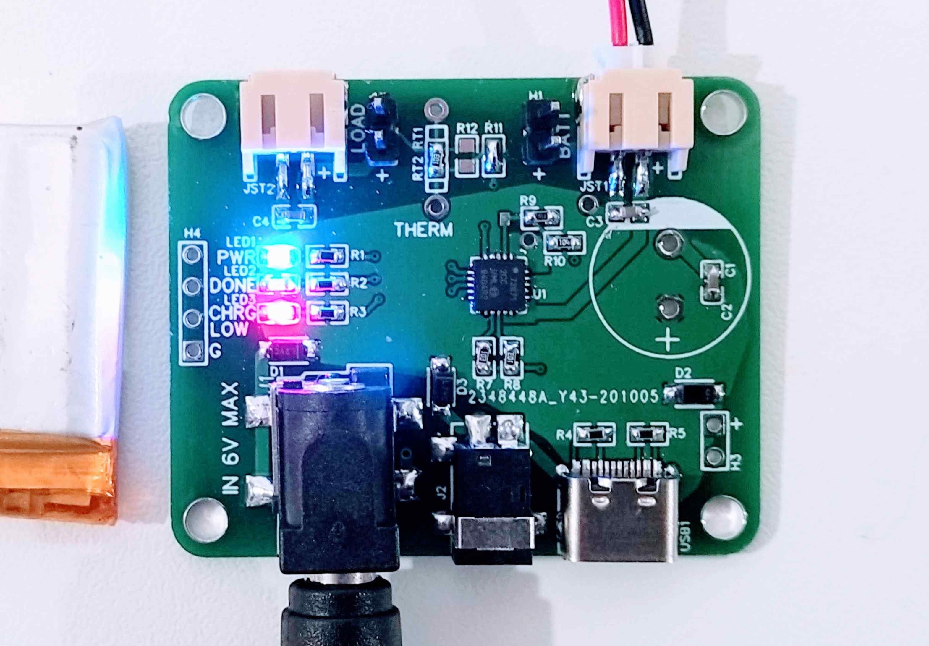
This circuit is a charger for single-cell lithium (Li-Ion) and polymer (LiPo) batteries. It can draw power from a DC jack connector (two different sizes), USB-C, and a solar panel. It uses the MCP73871, which features intelligent regulation of current sinking, making it ideal for solar applications where available energy can be scarce and vary widely over time.
The main application of this circuit is to charge the small battery of the weather station, which is a low power system and basically not easy to maintain. Therefore, battery life should be extended as much as possible. Therefore, avoid recharging at maximum capacity (set a high current threshold to stop it) and limit the maximum recharge current to 100mA. However, these values can be changed instead of the values of the resistors (see schematic).
It does not integrate any protection for Li-Polymer batteries (except for the optional thermal monitor), so use batteries that already come with integrated overcharge, overdischarge, overcurrent, short circuit protection, and optional overtemperature protection.
This project originates from Adafruit [USB/DC/Solar Li-Ion/Polymer Charger - v2](https://www.adafruit.com/product/390). If you just need a cheap alternative to the Adafruit board that doesn't have special form factor requirements, you can search (AliExpress) [[https://www.aliexpress.com/af/mcp73871.html](https:/ /www.aliexpress.com/af/mcp73871.html)].
The main differences from the Adafruit version are:
* USB-C connector instead of micro USB * Added DC jack connector 3.5x1.3mm * Protection diodes on each input, except USB-C ## Main components * Microchip MCP73871 * USB -C Connector * 2 JST-PH 2-pin * DC050 Jack Connector (5.5x2.1mm) * DC045 Jack Connector (3.5x1.3mm) ## Assembly
You will need a heat gun to fabricate the USB -C and fine-pitch components such as the MCP73871.
NOTE: Through-hole giant capacitor C2 is optional. The purpose is to increase efficiency when the solar panel cannot provide enough current (at least 30mA) for stable charging. This happens frequently (for example, at sunset, dawn, or on a cloudy day). In this case, the MCP73871 continues to turn on and off at a frequency that depends on the available solar energy. Continuously turning on and off can cause "charge shooting", which reduces charging efficiency, especially as frequency increases (>100Hz). You can limit this problem by adding a large capacitor, say hundreds or thousands of microfarads. So if you need to clean up every bit of energy, I recommend using a 4700uF capacitor, which is the "best" value chosen for Adafruit's breakout board. However, if circuit size is important, smaller capacitors can be chosen without incurring any considerable losses. For example, I've tried the 2200uF, which is less than half the size, with no noticeable change in efficiency. If you try different values, please let me know!
## Usage
In addition to USB-C, you can safely connect multiple power supplies (max 6V) because they are protected. The board can supply current to the load even if the battery is not connected (4.2V, maximum current regulated by R8-PROG1). Since protection dissipates a bit of energy (especially precious when using solar panels), you may consider shorting and removing the diode at your own risk.
## Changelog* 1.0.0 ⚠: First version. 5.5x2.1mm connector has wrong pinout and easily secures with simple wire* 2.0.0 ✅: Secures DC050 connector; Larger profile, allows capacitor flex; Adds plated mounting holes for M3 screws; Rounded corners # ## Version control convention
Each printing plate has a version. Version improvements will be made according to semantic versioning rules accordingly.
To show the status of each version, I use the following symbols:
* *White repeated check mark* (✅) means it was successfully tested; * *Negative squared cross mark* (❎) means it was almost successfully tested (the main feature is good), But there are bugs that affect minor functionality; * *Warning mark* (⚠) means that the board does not work out of the box, but bugs can be fixed in a DIY (decent) way; * *Cross mark* (❌) means that there are some issues that make it Not available; * *White question mark ornament* (❔) means untested.


 京公网安备 11010802033920号

 240-0322-37SCC6J7-18L


