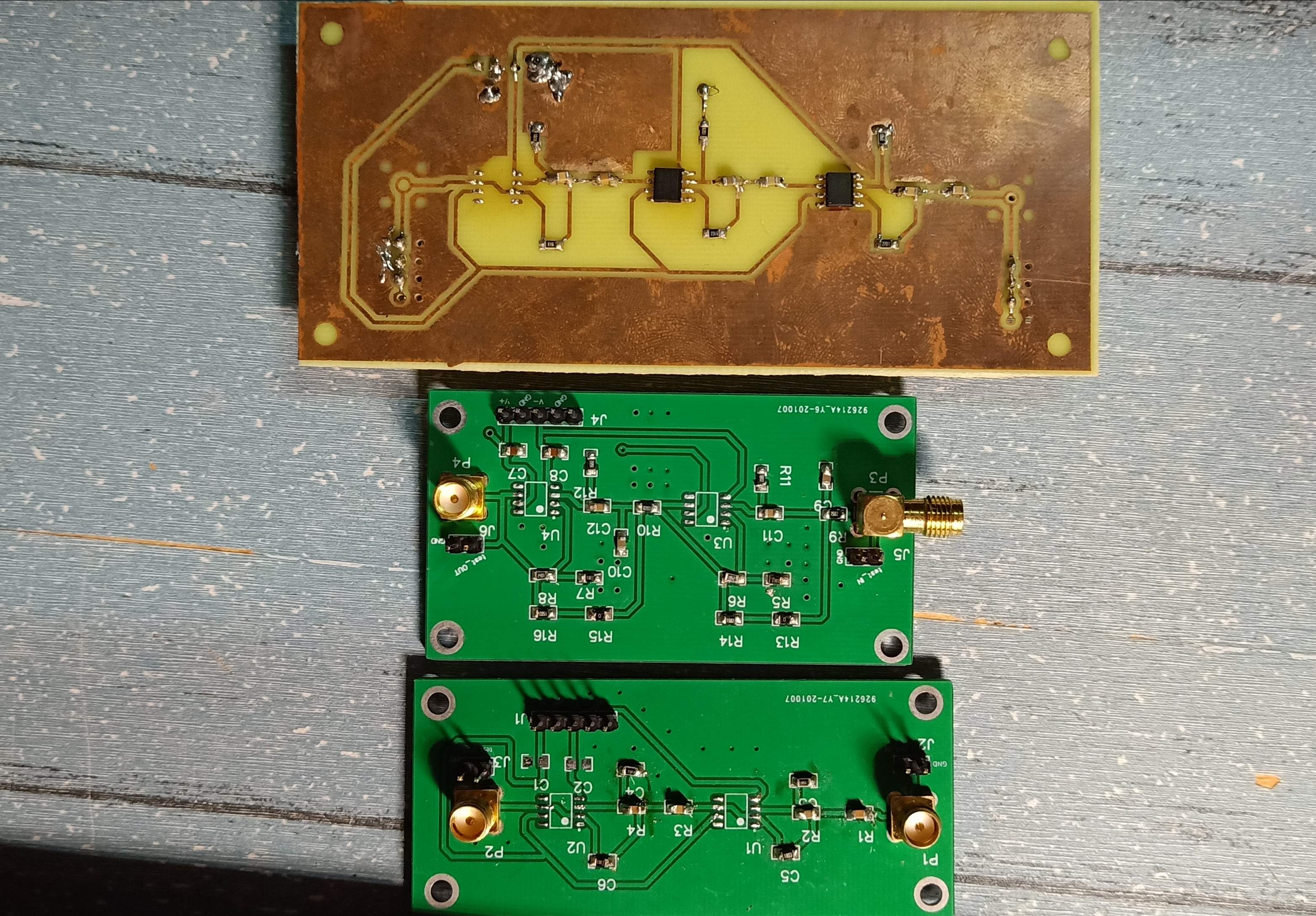
Detect small signals and signal detection in the presence of strong interference, and measure the effective value of the data.
When used, it also requires the cooperation of the analog switch and the microcontroller. It belongs to other circuits, so it is not included.
Input the signal to be measured into the band-pass filter for filtering. The fourth-order band-pass filter can filter out strong interference noise, leaving only the small signal to be measured. At the same time, the filter also has a certain gain to amplify the small signal first. .
Then it is input to the inverter and combined with the electronic switch to achieve the detection effect. Considering that the signal at this time is still very weak, if a general rectifier circuit is used, it will not work properly, so a solution of analog switches combined with a microcontroller is used. If the signal to be detected is large enough, there is no need for microcontroller control and the precision rectifier module can be used directly.
The rectified circuit is first processed by a first-order RC, and then passes through a fourth-order low-pass filter to directly extract the DC component. At this time, the DC component may not be amplified enough to be detected accurately, so a DC amplification module can be added to further amplify the signal to be detected to facilitate detection.
Considering that the input waveform will inevitably produce a certain phase offset after flowing through the circuit, a microcontroller is required to calculate the phase offset and construct a phase shifter so that the square wave signal it outputs to control the analog switch can be between 0° and 180°. tune. During this period, observe the output voltage and adjust it until the output voltage reaches the maximum.
In addition, when detecting high-frequency weak signals, a first-order RC filter (R>10, C>1nF) should be added to each connection of the module to reduce glitches.

