ELRS open source project address https://github.com/ExpressLRS/ExpressLRS/
ELRS firmware configurator https://github.com/ExpressLRS/ExpressLRS-Configurator/
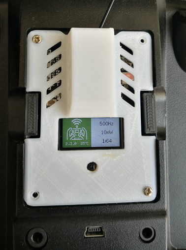
V3 version IPS color screen + button + backpack + fan fully integrated
See the attachment for full set of information download
Features:
Modular assembly E28, ESP32, DCDC voltage regulation, single-sided integration.
Cool color screen, 5-dimensional button, backpack function, cooling fan, RGB light.
Simple shell is easy to print, and the screen button fan is fixed on the transmitting motherboard.
1. ESP32 module, ESP32-WROOM UE without antenna is recommended, or ESP32 U and other 32 modules with the same interface are all OK. If you use a pcb antenna, you need to cut it off.
2. Ebyte e28 2g4m27s RF module, lora modulation signal, SX1280 chip. You need to replace the resistor to use an external antenna and cut the pcb antenna.
3. The extended display board is plugged into the launch board through a 1.27mm female row to reduce the complexity of the shell.
4. The 0.96-inch TFT color display has a resolution of 160x80 and supports plugging in bare screen 8P and welding bare screen 13P.
5. The 5-way button controls the screen, and the high-frequency head can be powered by USB externally, which is convenient for non-open source remote control.
6. The launch board and the expansion board are basically single-sided layouts, which is convenient for welding with a ten-dollar "LED desoldering station" to reduce the difficulty of production.
7. The cooling fan can be fixed on the launch board and is not higher than the bottom box space to reduce the complexity of the shell.
8. JR socket B2541BW is not easy to buy. You can consider buying a 2.54 staggered pin female row (5p, more can be cut), which has been designed with corresponding pads. When purchasing the female row, pay attention to the plastic height not exceeding 7.1mm, otherwise the contact will be poor.
9. Thanks to AXIS for promoting the color screen, and the boot interface temporarily uses his picture.
10. The 5-dimensional buttons use voltage divider resistors 5K, 5K, 10K, and 20K (5K can be equivalent to 2 10K stacked high). According to the schematic diagram, the values obtained by voltage division are 1/3, 1/2, 2/3, 4/5, 0, and 1. According to the pin sequence 16342- and *4096, the values of 'up, down, left, right, and middle' are 1365, 3276, 2048, 2730, 0, and 4095.
11. The simple shell is easy to print.
12. The external interface 1.25 socket can be connected to an external 5-24v power supply, and the external input Sport remote control signal can be used to lead to the tx rx flash port. (Newly added in v3.2 version)
Note:
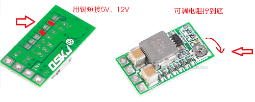
1. First adjust the DC step-down module to 3.45V (then apply tape on the entire back for insulation), switch E28 to select the external antenna, and cut the pcb antenna.
2. The external power supply is recommended to be greater than 7V.
3. High frequency head fan cooling fan 25x25x7mm, mounting hole 20x20mm fixed to the launch board, the fixing method is up to you. Note that the blades cannot touch the E28 and the shell.
4. Flash the launcher, solder the minimum necessary components ESP32 module, 3216 tantalum capacitor 10uf, adjacent 10k resistor, boot button, three 100 ohm resistors. (Short circuit must be tested after soldering) Use USB-TTL tools (ch340g, etc.), connect according to the instructions on the bottom, press boot and connect to the computer.
5. You can flash the ordinary DIY E28 firmware on the ground station first, and then enter wifi to flash the TFT color screen firmware I provide.
6. If only the middle button of the 5-dimensional button is effective, please remove it and rotate it 180 degrees for soldering, because different manufacturers may swap the 5-pin com ground with the 2-pin cent. When desoldering the SMD module, insert a thin razor blade when the soldering iron heats the pins, and the pins can be separated one by one.
7. The backpack function on the back of the launch board needs to be flashed with 01f before soldering ESP32 to communicate with 01f.
8. If the RGB light does not work, consider rotating it 180 degrees to mark which foot is facing the upper left. To be compatible with different pin definitions.
9. When soldering, open the corresponding html file to view the placement of components.
For a TFT screen using a plug-in cable, the thickness of the two PCB boards should be 1.6mm;
JR bottom box inner height 17-stud 4.5, available height 12.5; - Button height 2mm (1.5mm including the screen) - Upper PCB board, i.e. expansion board 1.6mm - 1.27 pin row plastic 1.7mm - 1.27 row mother plastic height 4.6mm - Bottom pcb launch board 1.6mm = 1mm Reserve the gap between the screen and the upper cover of the box.
If a soldered TFT screen 13p is used, because the cable occupies the space at the bottom of the screen, it is recommended that the PCB thickness is 1.2mm and the 1.27 row mother plastic height is 4.3mm. To use the joystick function, you need to modify the following files src/include/target/DIY_2400_TX_ESP32_SX1280_E28.h
based on the official one 1. Add the enable button function at the beginning #define HAS_FIVE_WAY_BUTTON 2. Define the ESP32 GPIO pin used by the joystick button #define GPIO_PIN_JOYSTICK 35 3. Set the voltage divider value for each direction of the five-way joystick // The V3 version of the TFT expansion display board has five-dimensional buttons (5k5k10k20k voltage divider) using this / Joystick values {UP, DOWN, LEFT, RIGHT, ENTER, IDLE}*/ #define JOY_ADC_VALUES {1365, 3276, 2048, 2730, 0, 4095} Voltage divider value calculation method: The joystick is connected to 3.3V through a 10K resistor to obtain a reference voltage. Measure the joystick - GND voltage reading V when pressing different direction buttons, V / 3.3 x 4096 = values. 1. First adjust the DC step-down module to 3.45V (then apply tape on the back to insulate), and switch E28 to select the external antenna. 3. Solder the ESP32 module, 3216 tantalum capacitor 10uf, 10k resistor, and boot button. You can use a 10 yuan "PTC heating table/LED desoldering table" for soldering: pre-tin the pad with a soldering iron (apply flux paste if conditions permit), place the components one by one, move the PCB to the heating table and heat it for a while until the tin melts and the soldering is done. The victory of the hand-clumsy party 4. USB TTL serial port tool (CH340) flashes the firmware and connects to the PCB board: TTL transmitter PCB TX---------RX RX---------TX 3.3V-------3.3V GND-------GND Note that the serial port tool must be 3.3, don't connect 5V! ! !
5. Press and hold the BOOT button to connect to the computer USB port.
Select the target DIY_2400_TX_ESP32_SX1280_E28 (for transition, the tft screen will not light up, see the following steps to flash the customized firmware that supports tft) on the ground station, and use the UART flashing method.
Check the parameters and the frequency password and click Start.
After the prompt is successful, disconnect all connections, then weld the B2541 socket, RGB light, DC buck module, E28 module and other originals, and connect the IPEX1 adapter and 2.4G antenna to the E28.
Tips: In the future, you can use WiFi to flash the firmware (the high-frequency head will enter the WiFi upgrade mode and the green double flash will appear if it is not connected to the remote control for 60 seconds after powering on) to flash the customized TFT firmware provided in the attached compressed package.


 京公网安备 11010802033920号

 C7S-80.000-16-1530-3-R


