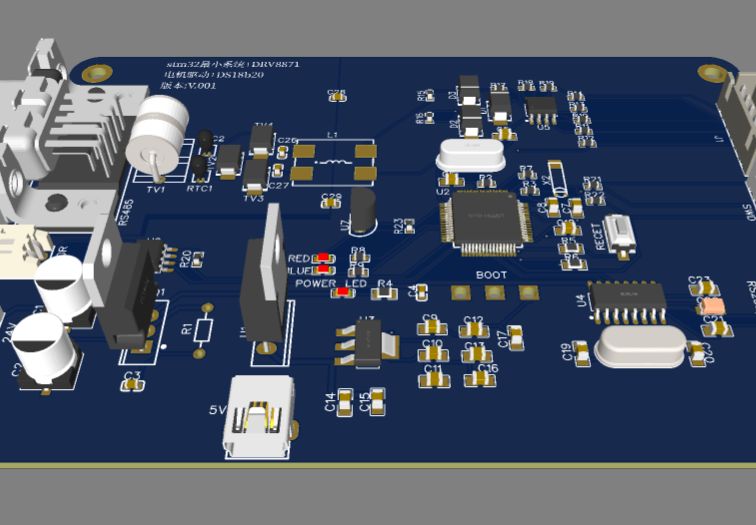
1. The RS485 interface is designed to meet the lightning protection test requirements of IEC61000-4-5 or GB17626.5 standards, common mode 6KV, differential mode 2KV. D4 is a three-terminal gas discharge tube that forms the first-level protection circuit to suppress the line. Common mode and differential mode surge interference to prevent interference from affecting the next stage circuit through the signal line. The nominal voltage VBRW of the gas discharge tube is required to be greater than 13V, and the peak current IPP is required to be greater than or equal to 143A. The peak power WPP is required to be greater than or equal to 1859WPTC1 and PTC2 are thermal sensitive The resistor forms the second-level protection circuit. The typical value is 10Ω/2W. To ensure that the gas discharge tube can conduct smoothly, this resistor must be added to divide the large energy to ensure that most of the energy goes through the gas discharge tube D1~D3. It forms a third-level protection circuit for TSS tubes (semiconductor discharge tubes). The nominal voltage VBRW of TSS tubes is required to be greater than 8V, the peak current IPP is required to be greater than or equal to 143A; the peak power WPP is required to be greater than or equal to 1144W;
2.1.TIP32C is a high-power PNP Type transistor, UCEO=100V, IC=3A (continuous) or 5A (peak), power dissipation PD=40W; L7805 realizes 5V voltage regulation;
3.GC8871/DRV8871 brushed DC motor driver chip with internal current sensing function , suitable for printers, electrical appliances, industrial equipment and other small machines. Two logic inputs control the H-bridge driver, which consists of four NMOSs and is capable of bidirectional motor control at peak currents up to 3.6A. Current decay mode allows the motor speed to be controlled by pulse width modulation (PWM) of the input. If both inputs are driven low, the motor driver will enter a low-power sleep mode.

