1. Product introduction:
An automatic step-up and step-down balancing charger that supports 6S lithium batteries and can achieve high-precision voltage detection. This product can also be used as an adjustable power supply.
2. Product parameters
8/31 Updated shell design Printing is completed (because the motherboard has not yet been SMT finished, so only the screen is installed)
QQ Group 730049694
This work follows the CC-BY-NC-SA 3.0 open source agreement. The forked project must indicate the original author and provide the original project link, and indicate whether any modifications have been made based on the original project. If you remix, If you convert or create based on this work and make it public, your project must also follow the CC-BY-NC-SA 3.0 open source license. Commercial use of this work and its derivative works is prohibited!
1. Product Introduction
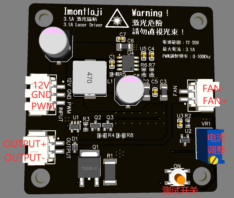
This module supports 0-100K TTL modulation, drive waveform rise time <2us, maximum output current 3.5A, input voltage 12-20V.
2. Application scenarios
1. Laser engraving machine
2. Laser light source
3. Stage laser
3. Product overview
It can drive laser diodes of various wavelengths. The output port is designed with an ESD protection device to prevent static electricity from damaging the laser diode.
This module reduces the input power supply voltage to 5V, and then uses a voltage-controlled constant current source to drive the laser diode. The TTL/PWM signal is directly input into the op amp, so that the rise time of the module's output waveform is shorter, thereby increasing the modulation frequency.
The buck part uses MPS's synchronous buck chip MP8715, which has a conversion efficiency of about 95% and significantly reduces heat generation.
The voltage-controlled constant current part uses TL431 as the reference source, and the LM321 operational amplifier controls the N-MOSFET to ensure stable output current. At the same time, compared with the scheme of inputting TTL/PWM signal to the DC/DC chip, it can obtain a higher waveform rise speed.
4. Product parameters
4.1 Electrical parameters
1. Working voltage: 12V-20V
2. Maximum output current: 3.5A
3. PWM/TTL modulation frequency: 0-100Khz
4. Fan interface output voltage: 5V
4.2 Interface parameters
Power input interface: 12V , GND, PWM
laser output interface: OUTPUT+, OUTPUT-
Fan output interface: FAN+, FAN-
4.3 Mechanical parameters
PCB size: 60mm * 60mm Double-layer board design Single-sided layout
Screw hole position: M3 50mm * 50mm
5. Instructions for use
Connect 12V and GND are connected to the 12V-20V power supply (12V recommended), and PWM is connected to the PWM/TTL output port or switch. (The PWM port needs to be driven by push-pull or strong pull-up. When the voltage is >3V, the laser is turned on and when the voltage is <3V, the laser is turned off.)
Then connect the 5V fan to the FAN port, connect the red and black test leads of the multimeter to the OUTPUT port, turn on the power input, and press ON button, observe the multimeter current and adjust the potentiometer until the current meets the requirements of the laser diode, then connect the laser diode to test and light up.
6. Remarks
1. This module is pure hardware and can be controlled by simply inputting PWM/TTL signals.
2. Pure manual welding, the cost is estimated to be 6-12 yuan/Pcs (all materials, including PCB).
3. Jialichuang SMT library does not have MP8715 and XH2.54 terminals. If you choose SMT to place an order, you need to manually repair these components. In addition, the 100K potentiometer also needs to be hand-soldered by yourself. There is a component purchase link in the attachment.
4. The type of chip aluminum electrolytic capacitor needs to be selected according to the working voltage. When working at 12V, 16V 470UF is required. For operation at a voltage higher than this, 25V 330UF is required.
7. Demonstration
waveform rise time test chart

video uses 3.5A current, 10Khz modulation frequency, 0-100% duty cycle to drive Nichia NUBM08 450nm laser diode
Schematic_Semiconductor Laser Driver-Supports 0-100K TTL modulation_2022-09-23.pdf
Modified from https://oshwhub.com/TheLight/zi-ding-yi-jian-pan.
The low axis was changed to Kaihua axis seat, the light was removed, and it was changed to 0603 package.
The overall board was raised a bit using Lichuang Professional If you print the shell on the accessory
shell, you can also use it by just laying down the shell. The PCB and the lower shell are flush (1.6-thick board). For
firmware burning, please see the original article by TheLight guy.
You can do it yourself as a novice. If you have a guy, you can try wiring it yourself.


 京公网安备 11010802033920号


 ROX150107KFNEEN


