Porter https://oshwhub.com/zanfi1010/shuo-ma-zhi-jia616_-you-hua_copy_copy_copy_copy_copy_copyChange to size
1. Source: This circuit is modified based on the 616 circuit circulated on the Internet. As for the origin of the 616 circuit, I have not fully verified it (in fact, why it is called 616, I have not found accurate information). According to online information, it is a great god of Digital Home. This project is also inspired by relevant online resources. For the P-Mos version and the N-Mos version, I prefer the P-Mos version, which has higher reliability. I am very grateful to the predecessors for laying the foundation.
2. Advantages: The circuit is simple and reliable, heats up quickly, and can effectively maintain a constant temperature. Analog circuits are not restricted by the soaring prices of chips. The material cost is extremely low, and it is not painful to toss around at will.
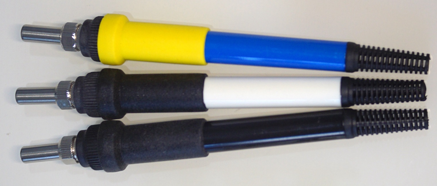
2. Applicable handles:
3. Improvement points:
(1) Improved the reference voltage circuit of LM358 pin 2: Since R4 is much larger than R8, R11 and R12, and R7 is much larger than R8, the reference voltage of LM358 pin 2 caused by R4 and R7 can be ignored, and can be calculated by a simple resistor voltage divider formula, and R7 can be ignored when calculating.
(2) Added reed switch sleep function. When in sleep mode, the voltage of LM358 pin 2 depends on the voltage divider of R12. Therefore, no matter what temperature the potentiometer is adjusted to, the sleep temperature is always the same. The soldering iron rack needs to add a magnet to use the sleep function.
4. Some notes:
(1) The control board cannot be made shorter, and its length is greater than 100mm;
(2) A thermometer is required. Different manufacturers produce different T12 soldering iron tips and thermocouples. Different LM358s also have different degrees of influence on temperature. The resistance values of R8, R11 and R12 determine the maximum temperature, minimum temperature and sleep temperature respectively. The resistance values shown in the figure are for reference only, or in other words, they need to be adjusted appropriately after the board is tested. After testing, the original 616 circuit also has this situation.
This circuit can also be changed into a separate control board, and some or all of R8, R11 and R12 can be replaced with adjustable resistors to adjust the maximum temperature, minimum temperature and sleep temperature separately.
(3) I did not spend the effort to find a more practical potentiometer R7, which is not convenient for adjusting the temperature in actual use. I adjusted it to 320℃ and used it at a constant temperature.
(4) In order to reduce the PCB area, the PCB is not silk-screened, and the artifact IBOM is uploaded in the attachment.
(5) The component model and package directly refer to the BOM of LiChuang EDA; but I did not purchase the components in LiChuang Mall, so the supplier number may not be accurate.
V. References:
(1) Working principle of the control circuit of Baicai Baiguang T12, how does the two-wire heating core achieve heating and temperature measurement?
(2) Analysis of the working principle of T12 soldering iron, see how T12 performs temperature control
(3) Analysis of the driving circuit of Baicai Baiguang T12 (I have doubts about the base state of the N-Mos version of the transistor, it is recommended for reference only)
(4) Add a sleep function to the hollow scaffolding T12
(5) Some other information can be found in the attachment


 京公网安备 11010802033920号

 SF0070BA03049S


