This project describes
a Category 4 PD power receiver decoupler based on the TPS2378, outputting 12V 2.5A/30W IEEE802.3at (POE+). The circuit can also be modified to support Categories 1-3 (0-13W).
Chip Introduction: (TI chip datasheet)
TPS2378 PD Power Receiver: This 8-pin integrated circuit contains all the functionality required to implement an IEEE802.3at Category 2 powered device (PD). The controller features an internal switching resistance as low as 0.5Ω and is housed in a thermally enhanced PowerPAD package, enabling extended operation at currents up to 0.85A. The TPS2378 has an Auxiliary Power Detection (APD) input for priority connection to an external power adapter. The device also features a 100V on-state transistor, 140mA inrush current limiting, Category 2 indication, automatic retry fault protection, and an open-drain power-on output.
Open source license
© 2023. This work is licensed under CC BY-NC-SA 3.0 CN
, which means: Creative Commons Attribution-NonCommercial-ShareAlike License.
CC: Abbreviation for Creative Commons license.
BY: Attribution. You must give appropriate credit, provide a link to this license, and indicate whether you have made modifications (to the original work).
NC: NonCommercial. You may not use this work for commercial purposes.
SA: ShareAlike. If you remix, transform, or build upon this work, you must share and distribute your contributions under the same license as the original.
For details, refer to the CC BY-NC-SA 3.0 CN overview .
Project-related functions:
A PD power receiver splitter based on TPS2378, supporting 30W (IEEE 802.3at, also known as PoE+), allowing only one network cable. PoE can transmit data while powering network devices, eliminating the need for cabling, simplifying the process, saving space, and allowing for easy device movement and high flexibility.
Project attributes:
This project is being publicly released for the first time and is my original work. The project has not won any awards in other competitions.
Project Progress
: Overall project progress; application for project consumable costs is required!
2023.01.11 Project created! Second PoE PD power receiving end project on the OSHWHub open source platform (the first PD project was also mine: MP8007H (whispering))
2023.01.20 TPS2378 - Schematic 1.0 completed
2023.02 SMT+PCB arrived
2024.02 Verification completed
Design Principles
Whether you buy a simple Ethernet switch or a wireless AP router, the accessories will include a bulky, boxy AC transformer (commonly known as a power supply), which is inconvenient to use. Is it possible to make the network cable both transmit signals and provide power? There are similar examples in our lives. For example, our ordinary landline telephone does not need an additional power supply; it only has a telephone line because the telephone line not only transmits voice signals but also provides power to the telephone (smartphones sometimes require additional power due to increased power). Thus, PoE (Power over Ethernet) technology emerged. PoE is a technology that transmits power and data to devices over an Ethernet network via twisted-pair cabling. The starting point of PoE technology is to allow small network devices such as IP phones, WLAN access points, and network cameras to draw power directly from Ethernet cables, eliminating the need for separate power lines, thereby simplifying system cabling and reducing network infrastructure construction costs. A complete PoE system consists of two parts: Power Sourcing Equipment (PSE) and Power Device (PD). The PSE provides power to Ethernet client devices and manages the entire PoE process, while the PD receives power and serves as the client device in the PoE system, such as IP phones, network cameras, access points (APs), and many other Ethernet devices.
Currently, PoE has three standards: IEEE 802.3AF, IEEE 802.3AT, and IEEE 802.3BT.
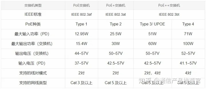
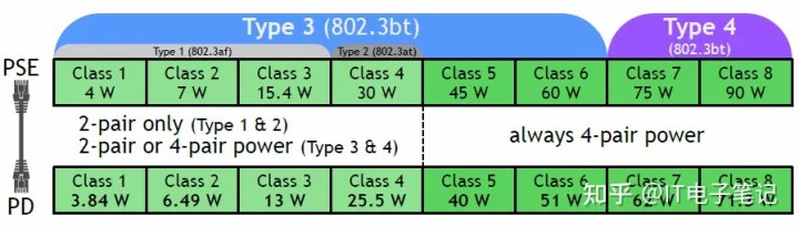
Power classification is a process where the PSE and PD negotiate the amount of power the PSE will allocate to the PD. During this process, the PSE and PD identify each other, determine the type of device they are connected to, and then the PD requests the power it needs. The PSE allocates the required power to the PD; if the PSE cannot meet the demand, it will reduce the power output. 802.3bt is backward compatible with 802.3at and 802.3af. A lower-power 802.3at or 802.3af PD can be connected to a higher-power 802.3bt PSE without any problems. However, when a higher-power 802.3bt PD is connected to a lower-power 802.3at or 802.3af PSE, the PD only needs to operate in the lower-power mode.
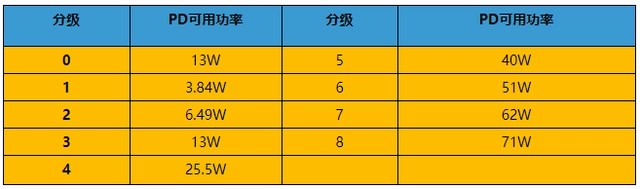
The PD in this project is a Class 4 device under the 802.3AT protocol.
Software Description
: The software can use nested code blocks. Only the important parts need to be explained, not all parts.
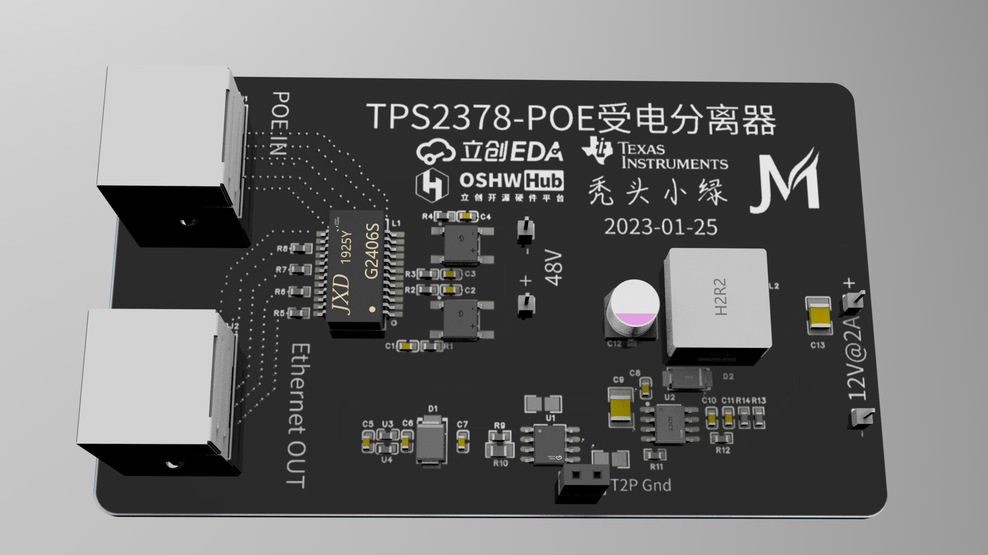
No physical sample is currently available. TPS2378-1.0-3D rendering (February 2023).
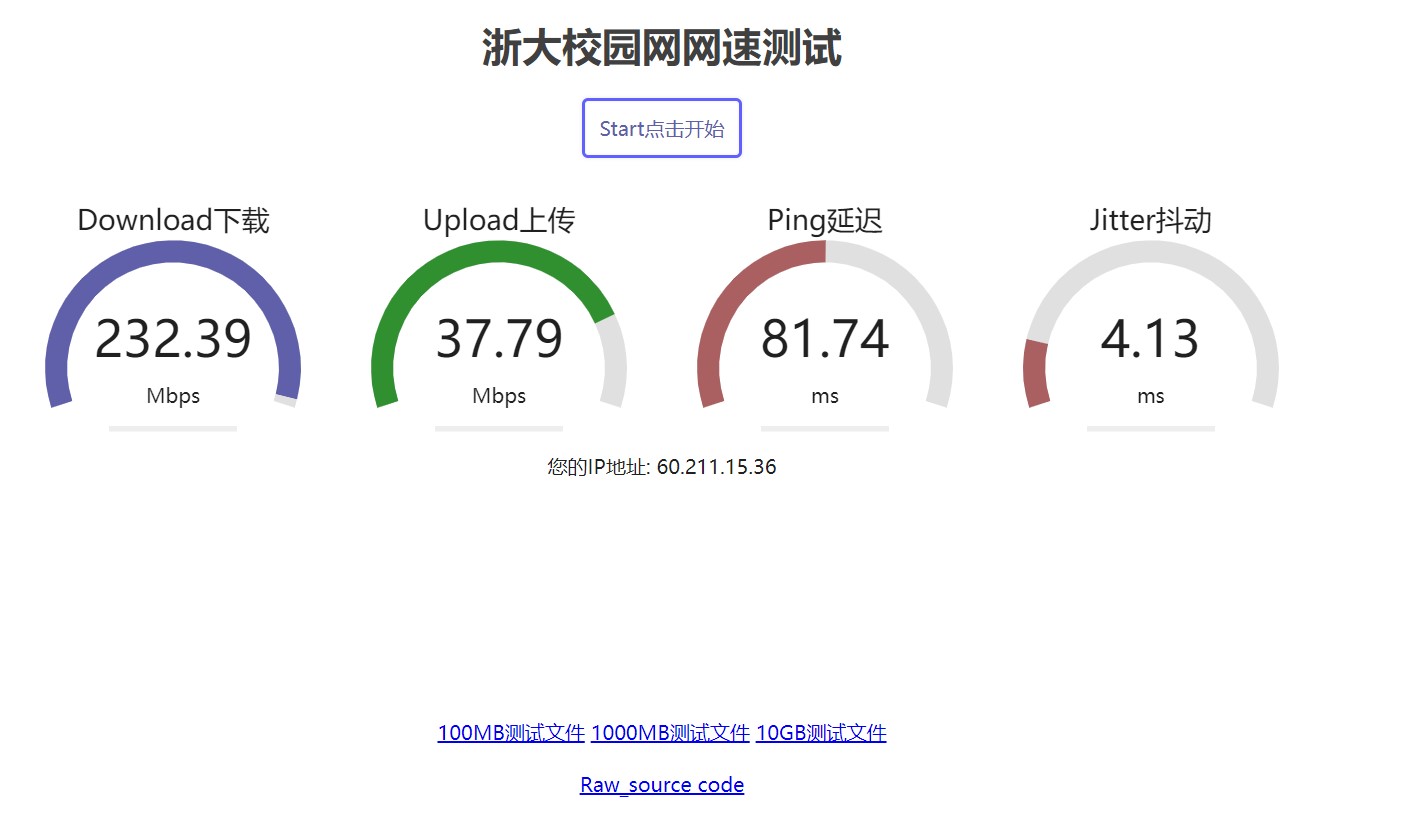
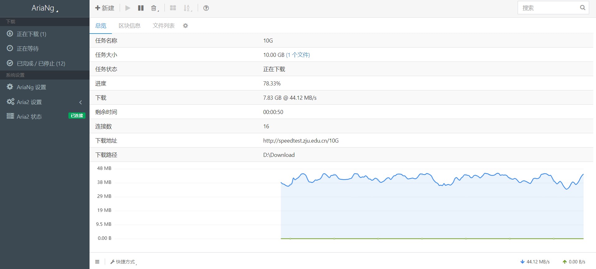
TPS2378 physical sample image (ignore the added 220uF electrolytic capacitor) (This differs from the final PCB design; the final PCB has been modified!). Design Notes : All model numbers are subject to the schematic! All model numbers are subject to the schematic! All model numbers are subject to the schematic! Please refer to the text descriptions in the schematic and compare them with the BOM! Other physical verifications: Test platform: Mercury SG108PL gigabit PoE switch, China Unicom home 300 Mbps broadband, USB 3.0 RTL8152B gigabit network card , electronic load tester as shown in the picture. SG108PL 5-port - PoE splitter input, PoE splitter output - USB network card - Computer negotiation speed recognition normal - gigabit speed test: (load 12V 2.1A) 1. Zhejiang University campus network speed test 2. Zhejiang University campus network speed test - 10GB large file download Postscript: Perhaps careful observers will notice that the webpage link for this project says PoE-power-system, but there is actually only one PoE splitter. Why is that? Perhaps you will also notice that the PCB and verification were separated by a year... Why is that? Actually, the original plan was for the system to include both PSE power supply and PD power receiver, but since a year ago, I have become increasingly busy and have less and less time... In the end, only the PD power receiver was completed...


 京公网安备 11010802033920号

 1N4685C-1


