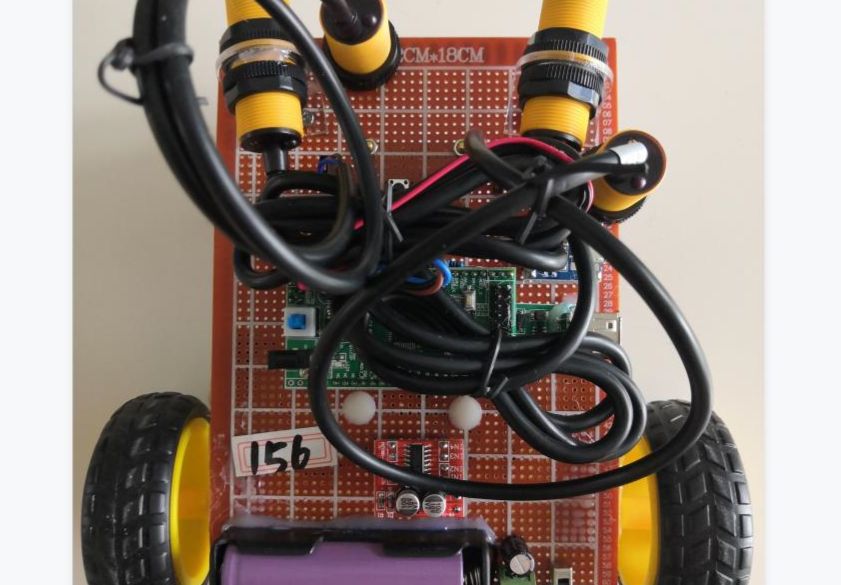
(I) System Function Design STM32 MCU Intelligent Sweeping Smart Car Robot Lithium Battery Charging 73 This system consists of STM32F103C8T6 MCU core board, 2-way infrared obstacle avoidance module, 2-way button, fan drive, motor drive, boost module, lithium battery charging module and battery box power supply. 1. After pressing the start button, the car starts, and at the same time, the fan rotates to suck dust; after pressing the stop button, the car stops rotating, and at the same time, the fan stops rotating. 2. During the operation of the car, if the infrared obstacle avoidance sensor module on the left detects an obstacle, it will turn right; if the infrared obstacle avoidance sensor module on the right detects an obstacle, it will turn left; if the infrared obstacle avoidance sensor module on any side detects an obstacle for more than a certain time (the car may not be able to move), the car will retreat and then rotate to turn around. Note: The ground should not be too smooth when the car is running to prevent the wheels from slipping. (II) System hardware system analysis and design 1. STM32 microcontroller core circuit design The STM32 series processor is a 32-bit microcontroller based on the ARM 7 architecture produced by STMicroelectronics ST, which supports real-time simulation and tracing. This control chip was selected because the design of this system does not pursue the lowest cost or lower power consumption, but can provide more abundant interfaces and functions under the premise of realizing the functions of this design to facilitate the design of peripheral expansion circuits required for various experimental projects of the experimental system. This control chip is relatively easy to use after completing the study of the microcontroller course. It is widely used in medical devices and has great learning and experimental research value. I. Main advantages of STM32: (1) Using ARM's latest and advanced architecture Cortex-M3 core (2) Excellent real-time performance (3) Outstanding power consumption control (4) Outstanding and innovative peripherals (5) Maximum integration (6) Easy to develop, allowing products to enter the market quickly II. STM32 - the best platform option For using the same platform for multiple project development, STM32 is the best choice: (1) From applications that require only a small amount of storage space and pins to applications that require more storage space and pins (2) From performance-demanding applications to battery-powered applications (3) From simple and cost-sensitive applications to high-end applications (4) The full range of pin-to-pin, peripheral and software high compatibility, giving you full flexibility. You can upgrade your application to require more storage space or streamline it to use less storage space/or use different packaging specifications without modifying your original framework and software. The interface circuit diagram of the STM32F103C8T6 microcontroller core board is shown in the figure below. . STM32 MCU core board interface schematic diagram 2. HC-SR04 ultrasonic obstacle avoidance sensor circuit design The ultrasonic module selected in this design is the HC-SR04 ultrasonic module. This module has stable performance and accurate distance measurement. It can provide non-contact distance sensing function of 20-400cm, and the measurement accuracy is 3mm. The module includes an ultrasonic transmitter, an ultrasonic receiver and a control circuit. It can be comparable to foreign ultrasonic ranging modules such as SRF05 and SRF02. The module has high precision, ultra-close blind area (2cm), and stable ranging, which is a strong basis for the successful market entry of this product! This module is fully compatible with the GH-311 anti-theft module. I. Main technical parameters of the module: (1) Operating voltage: DC5V (2) Static current: less than 2mA (3) Working current: 15mA (4) Working frequency: 40KHZ (5) Measuring angle: 15 degrees (6) Level output: high 5V (7) Level output: bottom 0V (8) Detection distance: 2cm-450cm (9) High precision: up to 0.3cm (10) Specification size: 45*20*15cm (11) Input trigger signal: 10uS TTL pulse (12) Output echo signal: Output TTL level signal, proportional to the range II. Module wiring method: (1) VCC connects to 5V power supply (2) trig (control end) connects to the microcontroller I/O port (3) echo (receiving end) connects to the microcontroller I/O port (4) GND ground wire III. Precautions (1) The TRIP pin is an internal pull-up resistor of 10K. Use the IO port of the microcontroller to pull down the TRIP pin, and then give a pulse signal of more than 10us. The OUT pin is the switch output pin when this module is used as an anti-theft module. The ranging module does not use this pin! (2) The module should be plugged into the circuit board before powering on to avoid high-level false operation. If it occurs, it can be solved by re-powering on. IV. Working principle of ultrasonic module: (1) Use IO to trigger ranging and give a high-level signal of at least 10us (2) The module automatically sends 8 40khz square waves and automatically detects whether there is a signal return (3) If there is a signal return, a high level is output through IO. The duration of the high level is the time from the ultrasonic wave from emission to return. (4) Test distance = (high level time * sound speed (340M/S))/2; (5) This module is easy to use. A control port sends a high level of more than 10US, and then the receiving port can wait for the high level output. Once there is an output, the timer can be started. When this port becomes a low level, the timer value can be read. At this time, it is the time of this distance measurement, and the distance can be calculated. In this way, the value of mobile measurement can be achieved by continuous periodic measurement. The test proves that the HC-SR04 ultrasonic module has superior performance and high sensitivity, which meets the requirements of this design. The module interface diagram is shown in the figure below. The specific physical diagram of the ultrasonic module circuit schematic is shown in the figure below. Ultrasonic module physical picture 3. MX1616 DC motor driver module This motor driver module is very suitable for use in battery-powered smart cars, toy cars, robots, etc. The power supply voltage is 2V~10V. It can drive two DC motors or a 4-wire 2-phase stepper motor at the same time, and can realize the functions of forward and reverse rotation and speed regulation. Each current can reach 1.5A continuous current, and the peak current can reach 2.5A. It has thermal protection and can automatically recover. I. Module highlights and parameters (1) It uses imported original professional motor driver chips, built-in low conduction resistance MOS switch tubes, extremely low heat generation, no need for heat sinks, small size, and power saving. (2) Dual 1.5A*2, peak current can reach 2.5A, built-in overheat protection circuit, no need to worry about motor stalling and burning, it will automatically recover after the temperature drops (3) Small size, light weight, 0 standby current (4) Dual H-bridge motor driver, can drive two DC motors or 1 4-wire two-phase stepper motor at the same time; (5) Module power supply voltage 2V-10V (6) Signal end input voltage 1.8-7V (7) Single-channel working current 1.5A, peak current can reach 2.5A, low standby current (less than 0.1uA) (8) Built-in anti-common conduction circuit, when the input end is floating, the motor will not malfunction (9) Built-in overheat protection circuit (TSD) with hysteresis effect, no need to worry about motor stalling (10) Product size: 24.7*21*5mm (length, width and height), ultra-small size, suitable for assembly and vehicle mounting (11) Mounting hole diameter: 2 mm Note: (1) Reverse connection of the positive and negative poles of the power supply will definitely cause circuit damage. (2) When the output is short-circuited to the ground or the output terminal is short-circuited, or the motor is blocked, the chip will be thermally protected, but when the voltage is close to or exceeds 10V and the peak current is much greater than 2.5A, the chip will also burn out. 2. The physical interface diagram of the module is shown in the figure below. Physical interface diagram of the module 3. Module driver truth table. Module driver truth table 4. Module interface schematic diagram is shown in the figure below. Module interface circuit schematic diagram 4. USB-5V boost module circuit design This USB-5V boost module is a DC-DC boost module (0.9V~5V) to 5V 600MA module. The module chip is 4X-NXH, that is, HX3001. It is a synchronous and efficient DC-DC boost converter with high-efficiency output, constant frequency, and PWM control. The device is silk-screened as 4X-NXH, and the chip is sot23-6-pin package. The circuit diagram is as follows. The device features 0.9V low voltage start-up, conversion efficiency up to 94%, medium power operation, and can provide 600mA, 5V/3.3V output. It is often used in portable players and other devices for efficient boosting. This design uses a DC-DC boost module to achieve a 3.7V lithium battery boost to 5V voltage conversion. 1. Module parameters (1) This module uses high-performance imported chips, and its performance is better than general modules. (2) Input 0.Any DC voltage from 9V to 5V can stably output 5V DC voltage. A single AA battery can output up to 200~300MA of current, and two AA batteries can output 500~600MA of current, which can power your mobile phone, camera, microcontroller and digital products. (3) Industrial temperature range: -40℃---+85℃. (4) High conversion efficiency, up to 96%. (5) With USB female socket, it has a wide range of uses. (6) Ultra-small size (PCB board 25mm*18mm), suitable for installation in various small devices. (7) With working indicator light. II. Interface description (1) IN+ input positive pole (2) IN- input negative pole (3) USB female port output 5VDC III. Instructions for use (1) The USB female port of this module outputs 5V DC voltage. If an external 5V power line is required, you can directly charge the 5V positive pad of the USB female port or jumper one end of the capacitor at a specific position on the front of the module to take the line. As shown in the figure below. Module 5V jumper wiring diagram (2) When soldering the USB-5V boost module, you can directly solder the power input terminal with a power cord, or you can insert a single-row pin and solder it and then plug it into a PCB board or a multi-purpose board. USB-5V boost module interface schematic diagram. After the switch is turned off, the boost module works normally and boosts the 3.3V lithium battery voltage to 5V. Otherwise, the boost module does not work. The capacitors in the circuit are all filter capacitors to make the voltage more stable. As shown in the figure below. USB-5V boost module interface schematic diagram The actual picture of the USB-5V boost module is shown in the figure below. USB-5V boost module actual picture 5. NEC infrared serial communication module circuit design Infrared is a means of short-range, high-speed wireless communication. As a short-range, indoor communication means, infrared has advantages that radio cannot match. 1. Module parameters (1) Power supply voltage: 5V (2) Communication mode: serial communication (TTL level) (3) Transmission distance: 6-10 meters (8 meters stable control in actual environment test) 2. Module function description (1) With NEC format infrared transmission function. (2) With NEC format infrared encoding function. (3) With infrared transmitter expansion interface. (4) With serial communication function, the communication level is TTL. (5) Can control 99% of NEC infrared format devices, including televisions, electric fans and other electronic and electrical equipment. (6) Support NEC encoding chips: (typical encoding chips such as uPD6121, uPD6122, TC9012 and many compatible chip models, such as PT2221, PT2222, SC6121, SC6122, SC9012, etc.) (7) Can be used for infrared wireless data communication, data transmission, infrared control and other functions III. Scope of use (1) Smart home (2) Student electronic design (3) Intelligent industrial control equipment (4) Infrared encoding and decoding equipment (5) Smart car remote control IV. Usage method (1) Send the specified command through the serial port to control the module to transmit; perform infrared encoding operation through the serial port receiving method to obtain the remote control code information. (2) Decoding: No command needs to be sent during decoding. Just pick up the remote control and aim it at the receiving head of the module and press it. At this time, the serial port of the module will output the infrared code. (3) Encoding (transmission): When encoding, you need to send commands according to a certain format. Send a 5-byte command through the computer or microcontroller serial port to restore the corresponding encoded infrared signal. 5. The module interface description is shown in the figure below. Module interface description diagram Module internal circuit diagram Module interface schematic diagram is shown in the figure below. Sensor interface circuit schematic diagram Module physical diagram is shown in the figure below. Module physical diagram 6. ESP8266WIFI module circuit design Circuit design ESP8266 is an ultra-low power UART-WiFi transparent transmission module with a very competitive package size and ultra-low energy consumption technology in the industry. It is designed for mobile devices and Internet of Things applications. It can connect the user's physical device to the Wi-Fi wireless network for Internet or LAN communication and realize networking functions. ESP8266 has various packaging methods, and the antenna can support three forms: onboard PCB antenna, IPEX interface and stamp hole interface; ESP8266 can be widely used in smart grid, smart transportation, smart furniture, handheld devices, industrial control and other fields. I. Module Features (1) Supports wireless 802.11 b/g/n standards (2) Supports STA/AP/STA+AP three working modes (3) Built-in TCP/IP protocol stack, supports multiple TCP Client connections (4) Supports rich Socket AT commands (5) Supports UART/GPIO data communication interface (6) Supports Smart Link intelligent networking function (7) Supports remote firmware upgrade (OTA) (8) Built-in 32-bit MCU, can also serve as an application processor (9) Ultra-low energy consumption, suitable for battery-powered applications (10) 3.3V single power supply II. The main functions that ESP8266 can achieve include: serial port transparent transmission, PWM control, GPIO control. (1) Serial port transparent transmission: data transmission, good transmission reliability, the maximum transmission rate is: 460800bps. (2) PWM control: light adjustment, three-color LED adjustment, motor speed adjustment, etc. (3) GPIO control: control switches, relays, etc. 3. Working Mode The ESP8266 module supports three working modes: STA/AP/STA+AP. (1) STA mode: The ESP8266 module connects to the Internet through a router, and the mobile phone or computer can remotely control the device through the Internet. (2) AP mode: The ESP8266 module acts as a hotspot, allowing the mobile phone or computer to communicate directly with the module and realize wireless control of the LAN. (3) STA+AP mode: The coexistence mode of the two modes, that is, it can be controlled through the Internet and can achieve seamless switching, which is convenient for operation. 4. Application fields (1) Serial port CH340 to Wi-Fi; (2) Industrial transparent transmission DTU; (3) Wi-Fi remote monitoring/control; (4) Toy field; (5) Color LED control; (5) Fire protection and security intelligent integrated management; (6) Smart card terminal, wireless POS machine, Wi-Fi camera, handheld device, etc. The WiFi module circuit diagram is shown in the figure below. WIFI module circuit schematic diagram The actual picture of the WIFI module is shown in the figure below. WIFI module physical picture 7. LY Bluetooth module circuit design Bluetooth module refers to a chip basic circuit collection with integrated Bluetooth function, which is used for wireless network communication. This Bluetooth module is specially designed for wireless data transmission. This module supports serial interface and SP Bluetooth serial port protocol. It has the characteristics of low cost, small size, high sensitivity of sending and receiving, and can achieve great functions with only a few peripheral components. I. Module Features (1) Support Bluetooth SPP serial port protocol (2) Built-in PCB antenna (3) Support UART interface (4) Bluetooth Class 2 (5) Data transmission is faster than BLE Bluetooth, and can reach a rate of more than 8K per second (6) Support connection and communication with SPP master Bluetooth module (JDY-30 is a slave SPP Bluetooth module) (7) Support SPP Bluetooth communication with computer (8) Support SPP communication with Android phone II. Product Application Scope (1) POS machine (2) Bluetooth printer (3) Bluetooth toy (4) Bluetooth high-speed data transmission product application (5) Small household appliances (6) Automotive electronics III. Module Technical Parameters (1) Working voltage: 3.3V-6V (2) Working temperature: -40℃-85℃ (3) Antenna: PCB onboard antenna (4) Power consumption: 19mA IV. Module Interface Description (1) RXD serial port input, level is TTL level (2) TXD serial port output, level is TTL level (3) GND Connect to GND (4) Connect to VCC 3.3V-6V Bluetooth module interface circuit diagram is shown in the figure below. Bluetooth module circuit schematic diagram Bluetooth module physical diagram is shown in the figure below. Bluetooth module physical diagram 8. 5V cooling fan control circuit (high level is effective) design The working principle of the cooling fan is realized according to energy conversion, that is: electrical energy → electromagnetic energy → mechanical energy → kinetic energy. Since the single-chip microcomputer cannot directly drive the vibration fan, the transistor 8050 is selected to realize the control of the cooling fan. The resistor is a current limiting resistor, which has a current limiting effect to protect the transistor. When the relevant control pin of the single-chip microcomputer is at a high level, the transistor is turned on and the fan works normally; otherwise, the fan does not rotate. The schematic diagram of its drive circuit is shown in the figure below. 5V fan control circuit schematic diagram 9. Key circuit design The touch key is a classified product under the key product. It is actually equivalent to an electronic switch. As long as the key is pressed lightly, the switch can be turned on. When it is released, the switch is disconnected. The implementation principle is mainly to connect and disconnect by the force of the metal spring inside the touch key. In this system, the button is used as the input of the system and plays a pivotal role in human-computer interaction. The microcontroller control pin of the button is high by default. When the button is pressed, the relevant pin of the microcontroller becomes low. Then the manual input of the system is realized. Note that the number of buttons can be changed. The circuit schematic is shown in the figure below. Schematic diagram of button circuit 10. Circuit design of E18-D80NK infrared obstacle avoidance sensor module E18-D80NK-N This is a photoelectric sensor that integrates emission and reception. The emitted light is modulated and emitted, and the receiving head demodulates and outputs the reflected light. It effectively avoids the interference of visible light. The use of lens also makes this sensor detect the problem of 80 cm distance at the farthest (due to the characteristics of infrared light, objects of different colors have different maximum detection distances; white objects are the farthest and black objects are the closest). The distance of obstacle detection can be adjusted according to requirements through the potentiometer knob at the tail. The sensor has the characteristics of long detection distance, small interference from visible light, low price, easy assembly and convenient use. It can be widely used in robot obstacle avoidance, assembly line piece counting and many other occasions. Application examples: automatic counting equipment for goods in production lines, multi-function reminders, maze robots, etc. I. Module parameter description (1) Photosensitive sensor (photoelectric switch) NPN normally open (2) Red: VCC +; Black: GND —; Yellow: OUT signal output. (3) Working voltage: 5VDC (4) Working current: 10-15mA (5) Driving current: 100mA (6) Sensing distance: 3-80CM adjustable (7) Color: orange (8) Diameter: 18MM (9) Length: 45MM (10) Lead length: 25CM. (11) Current consumption DC


 京公网安备 11010802033920号

 RP15-4805SAWN


