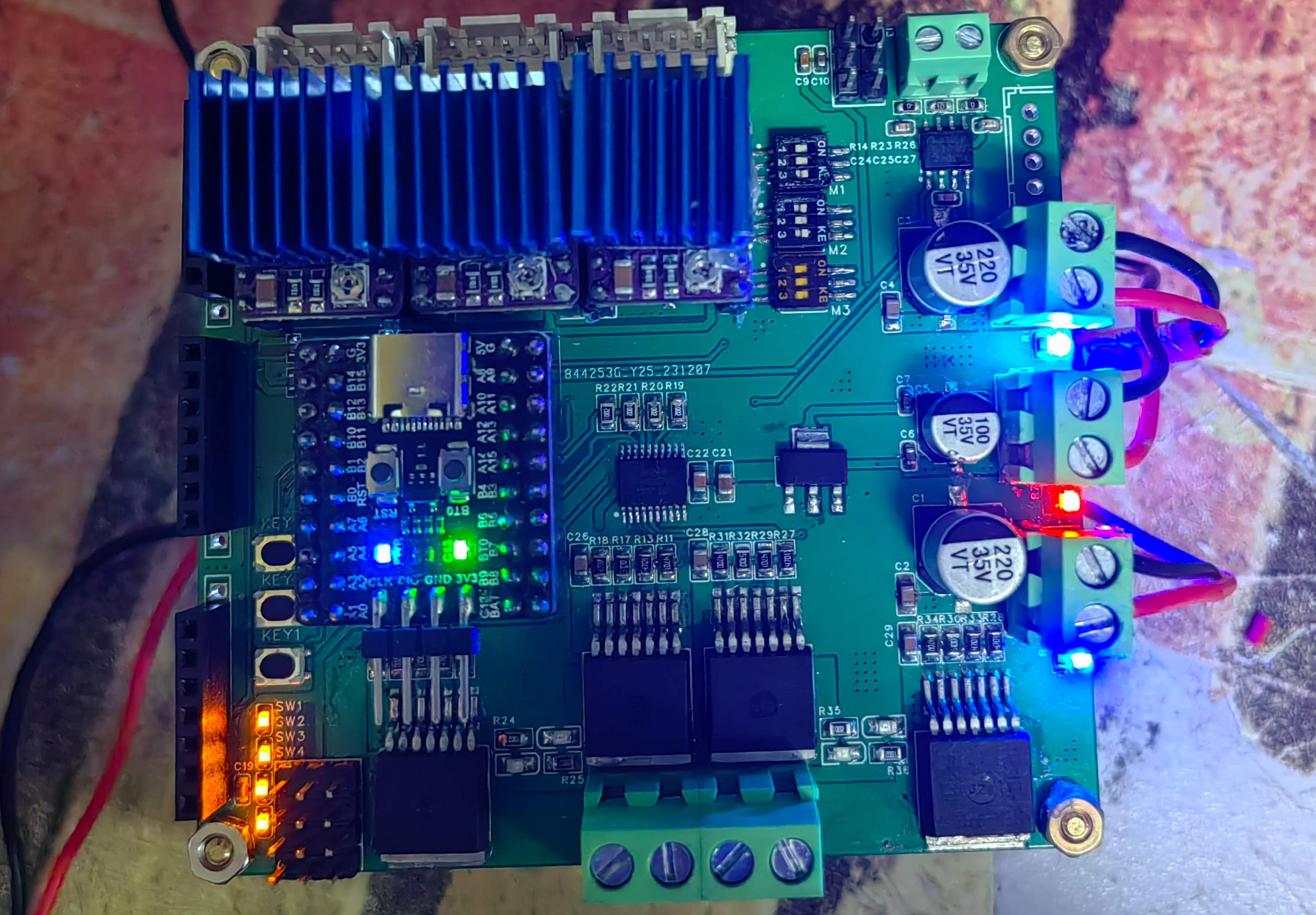
Regarding the motor drive section:
I. The stepper motors
use the DRV8825 as the driver, which offers higher drive current and lower noise compared to the A4988. An LED is added directly below the driver to display the input frequency on the STEP pin.
Each of the three stepper motors uses a separate hardware timer/counter to output PWM, and each uses a separate DIP switch for frequency division.
II. The high-power DC motors
use the BTN7971 as the driver, with a drive voltage of over 40V and a current of over 40A (see the chip datasheet for details). Because it's a four-layer board, the heat generation is not significant under 10+ minutes of 24V 2A conditions, making it suitable for driving actuators and small table saws.
A single BTN79710 is essentially a half-bridge driver; two BTN7971s are needed to form a full-bridge driver for a single motor. A 74HC245 is used as an isolation chip to protect the main controller, and two LEDs are added to the output port to indicate the output direction.
Both motors use software timers to generate PWM waves of approximately 1kHz. Theoretically, four BTN7971s can function as a new stepper driver (the principle is the same as driving a stepper with an L298N).
III. The 2D gimbal
is nothing special; it simply uses two pulse signals generated by a software timer to drive two digital servos.
Regarding the sensors:
I. INA226 Current/Voltage Sensors
: Three current/voltage sensors can detect the output status of high-power DC motors (the same applies to stepper motors). Theoretically, the detection limit is 30V 5A, and the resolution is quite high (see the chip datasheet for details).
Note: The direction of the bottom INA226 is opposite to the two above it.
II. Infrared/Photoelectric/Limit Switches:
Four infrared/photoelectric/limit switches. The leftmost is the signal line, with a built-in pull-up and an LED to indicate the switch status. The middle is the 5V power supply port.
III. Independent Buttons:
Three independent buttons for motor adjustment.
Regarding the power supply:
Three power input ports provide power inputs separately but share a common ground. The middle power input port directly powers the servos, so it is recommended that the voltage not exceed 6.5V. The other two input ports can be freely selected to supply voltage to the stepper motor and the high-power DC motor. Because the power supplies are separate, it avoids the problems of voltage and current loss during motor startup.
The video below shows the motor driver version V3.0, featuring a single-channel current sensor and two-channel stepper drivers; the rest is largely the same.
As a software developer, this is my first time working on open source, so please forgive any issues with the circuitry or the article. I welcome your suggestions below, or please share your more innovative ideas. Let's carry the open source spirit to the end!


 京公网安备 11010802033920号

 2200DGH500123MB


