Based on the KT06xx series chips and the ESP32-C3/ESP8266 series wireless microphones and receivers, it supports functions such as arbitrary frequency modification and automatic microphone/receiver pairing. It also supports configuration modification and OTA updates via Wi-Fi.
This project is entirely self-made, except for the receiver. The microphones were purchased off-the-shelf and modified. The receiver can pick up almost all analog signals.
The project was initially called "Wireless Microphone: From Beginner to Complete Set,"
but after being plagued by signal and noise issues for half a year, it has been officially renamed "Wireless Microphone: From Beginner to Giving Up."
Unfinished parts of this project may be continued next year.
Update Log
: Progress before 2023: Modified microphone verified as feasible; five or six receiver board versions were designed, all with extremely poor signal.
2023.03.15 The first KT0651 chip was barely usable, but the subsequent soldered chips all failed.
2023.03.20 Changed the driver; the first usable single-channel KT0656M chip was successfully verified.
2023.03.28 Spark project application approved; continued designing the board.
2023.05.15 First version of dual-channel KT0656M verified; various problems encountered; continued revisions.
2023.05.21 Bringing a complete DIY setup to a performance, successfully completed
on May 28, 2023. Dual-channel KT0656M second version verification; except for the antenna and signal, everything else is basically usable. On May 30, 2023,
bugs were found and fixed on KT0651; modified microphone testing of the second solution.
On June 14, 2023, KT0651 is usable; KT0656M has slightly high noise floor and needs rectification.
From July to September 2023, overtime work prevented me from focusing on the project . On October 2023
, the ground plane and antenna were redone, resulting in a significant signal improvement; basically usable.
On November 2023, parameter tuning and final verification were conducted; I plan to bring the equipment to another performance at the end of the month.
Project Introduction :
Main
Hardware Selection:
Transmitter Main Control: ESP8266 (When I started tinkering with the transmitter, the C3 hadn't been released yet.)
Receiver main controller: ESP32-C3 (having a USB serial port is great!)
RF chip: Quantum Micro KT06 series (the only single-chip analog wireless microphone solution on the market with available documentation) (Of course, it all started eight years ago when I bought a circuit board)
Headphone amplifier chip: TI TPA6132 (I thought TI was the best at the time, but adding a QFN made things worse)
Display: SSD1306/SSD1305 0.96-inch OLED (Would anyone actually use a color screen on this?) (Oh, yes, someone would)
—Software
selection:
ESP-IDF + Arduino, using functions from both sides, mainly focusing on a twist
(actually because the transmitter was initially written with Arduino, but pure Arduino development of the C3 had various problems, including adjusting parameters like sleep mode, so I migrated to IDF)
—Host
computer:
Node.js + Web, because my main job is a front-end
transmitter
1. Modifying a ready-made
handheld microphone: Buying a shell plus shipping is not as good as buying a whole microphone set on Taobao. Therefore, we chose to purchase a finished product directly and achieve more functions by replacing the main controller.
This project changes the transmitter to use the ESP8266 as the main controller, with an external SSD1306/SSD1315 0.96-inch OLED display, and uses a lithium battery as the power source, with optional TP4056 charging management.
Firmware supports the following functions:
quick mute, volume (gain)
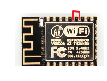
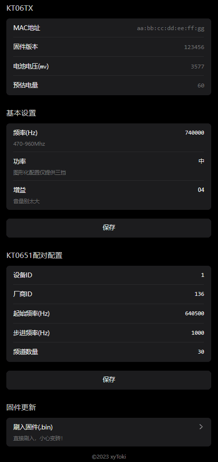
adjustment at any frequency , transmit power adjustment, display of a custom ID (English only, no Chinese character library) , transmission of battery level and mute status information to the receiver in this project, pairing with the receiver in this project (any frequency), pairing with the KT0651 receiver (requires some receiver configuration knowledge; this can be obtained by capturing the signal transmitted from the original microphone through the receiver in this project, or by reading the EEPROM chip connected to the KT0651 through a programmer), viewing and configuring parameters via Wi-Fi, and OTA firmware updates. The power button's high/low and flat states are all supported. Before installing the jumper wires, the original microphone's main controller and display need to be removed. Since there is no USB to TTL adapter on the board, it is recommended to flash the firmware onto the ESP8266 beforehand; otherwise, flashing the firmware later will be more complicated. After downloading the firmware from the attachment, simply flash it to pin 0x0 of the ESP8266. After the initial flash, subsequent firmware upgrades can be performed via OTA through the web interface without disassembling the microphone again. KT series chips primarily communicate via I2C, so after removing the original main controller, you need to bring out the SDA and SCL signal lines from the microphone motherboard. In addition, you'll need to bring out VCC, GND, the control line for the power switch (PWR_CTL), and two button lines. If you're lucky, the microphone board you received will have all these lines routed to the debug points, requiring almost no additional wiring; otherwise, you'll need to run more wires. Before wiring, you need to confirm whether the power button and setting button are triggered by a high or low level. Currently, only the power button supports switching trigger modes. If the setting button is triggered by a high level, the firmware I provided may not be suitable for this microphone. If the setting button is triggered by a high level, you need to short two pins of the ESP8266, as shown in the diagram. Below is a wiring diagram for the board I received; this board has all the necessary signals routed out, so simple soldering is sufficient. The other type I bought is more complicated. It requires making a flying wire to connect the signal line to the existing debug pins, and then soldering the connecting wires from the debug pads (this minimizes pad damage). This isn't very common, so I won't post a picture. If anyone needs to find the wiring, feel free to comment and discuss. Besides soldering the main controller, you also need to install an OLED screen, and if necessary, connect the lithium battery and charging port. The fully connected setup looks something like this: After completing the flying wire, try to put everything back in its place, and you're done. It looks strange, but it works.jpg The KT0656M can operate at any frequency from 470-960MHz, but the antenna will affect the transmission performance at different frequencies. Therefore, when adjusting the frequency, it's best to stay within the original microphone frequency range; otherwise, the signal may become very poor or even fail to transmit much at all. Due to ample Flash space, the transmitter provides a relatively aesthetically pleasing web interface for user adjustments. It looks like this: 2. Unfortunately, I couldn't complete the fully self-made project due to insufficient time and a lack of understanding of antenna-related aspects. I'll continue next year. Receiver 1. KT0651 - Simple Self-Searching Station Receiver


This is the same receiver as many microphones available on the market. The receiver is not configurable, but it can be paired with a microphone and can automatically search for channels. Most microphones on the market support 30 frequency points. However, this was initially copied because communication noise would interfere with the audio when making the KT0656M. After solving this problem, it was no longer iterated or produced.
The
channel search and pairing principle of the KT0651 is as follows:

Since the EEPROM configuration of KT0651 lacks documentation, only the method of modifying the frequency, device ID, and manufacturer ID is provided here:
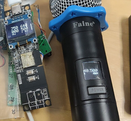
Open the file (16K) extracted from the EEPROM, find 0x3F00, as shown in the blue box in the figure, which is the starting frequency;
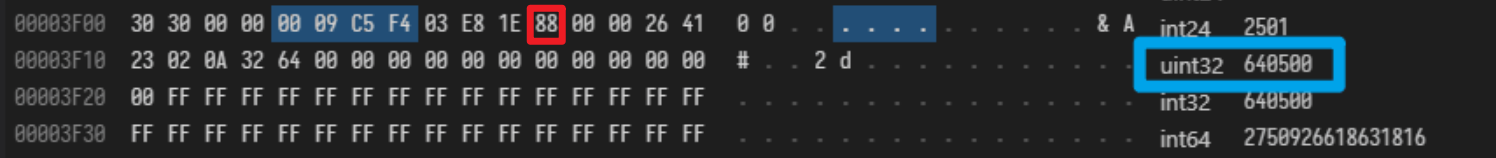
the following 0x03e8 is the frequency step (1000 Hz, i.e., 1MHz); the following 0x1e is the number of channels (30); and then the red box 0x88 is the manufacturer ID. The microphone in this picture has a common frequency of 640.5MHz. Most of the generic microphones sold on Xianyu (a second-hand marketplace) have this parameter. The configuration of this version will be provided in the attachment. You can directly flash the EEPROM to use it.
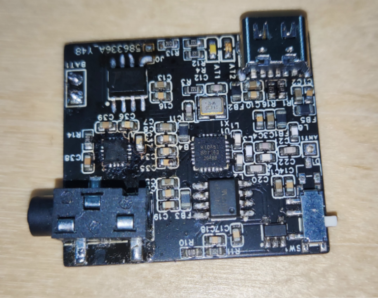
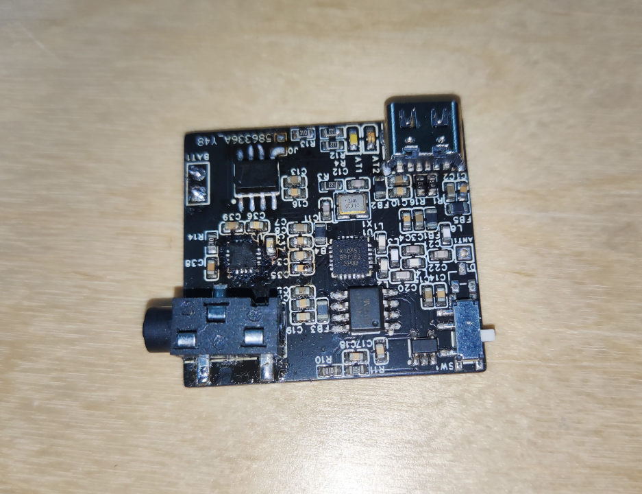
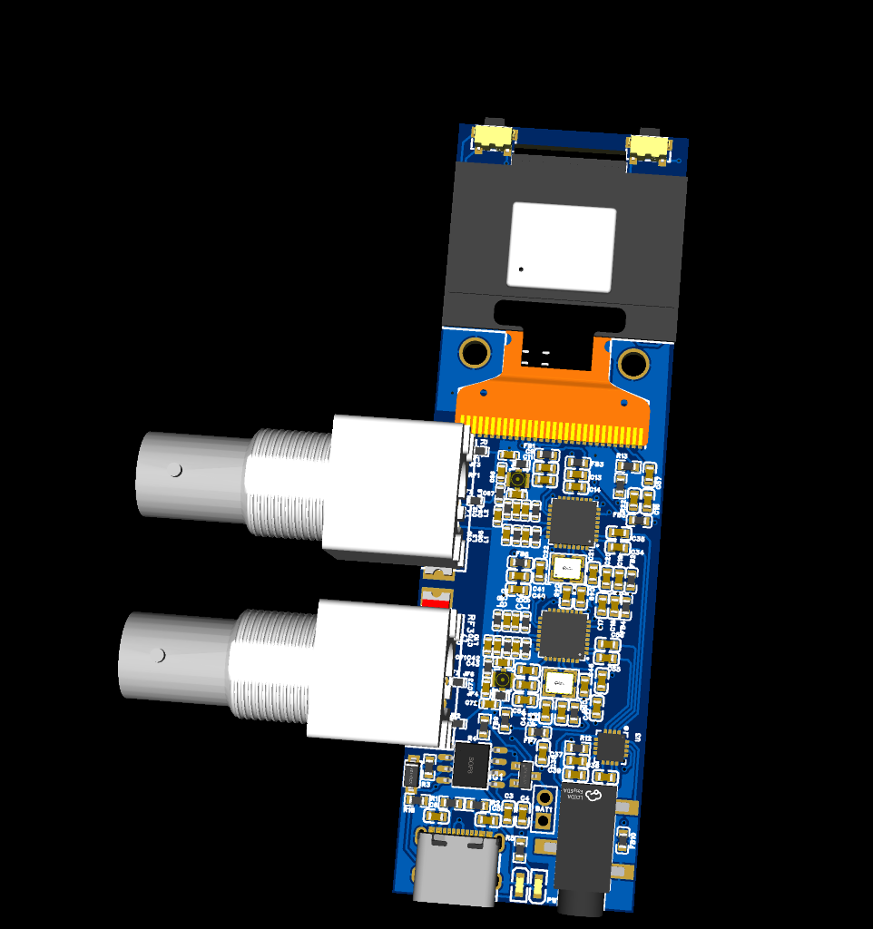
2. The KT0656M multi-functional dual-channel receiver with screen
is also available in single-channel version (see the board for details).

Adding an antenna and debugging the signal enhancement
receiver took the most time. My soldering skills were inexperienced, leading to various poor connections and a particularly weak signal. Next was noise. I tried different versions of ground isolation and differential signal, but even when the audio and power supplies were from the same device (e.g., the computer's power supply and audio output connected to the computer's microphone), significant interference noise persisted, presumably from I2C crosstalk. This issue remains unresolved; an audio isolator could be used. Finally, regarding the signal, although I tested it with an antenna analyzer, the KT chip doesn't provide information like its output impedance, making simulation almost blind. Therefore, I blindly tuned it based on the actual received signal. Current test results show that at an unobstructed distance of about 100 meters, with an external antenna, it's significantly stronger than the original receiver that came with the microphone (obviously, its antenna is longer). With an internal antenna, the performance is similar, but far inferior to the professional control group (although the professional control group is the Sennheiser EW 300). (Comparing it to the G2 is a bit of an exaggeration.)
Hardware features:
Single-channel version has balanced output, dual-channel version has single-ended output;
supports seamless switching between battery and external power supply; optional TP4056 charging management;
reserved internal/external antenna positions;
RF performance has been calibrated to some extent (using NanoVNA), but is not very accurate.
Firmware features:
Supports both single and dual channels; adaptive UI;
supports arbitrary frequency and volume adjustment
; supports pairing with the transmitter in this project; the receiver will adjust synchronously when the transmitter adjusts its frequency (using ESP-NOW, not UHF, requires the microphone to be close to the receiver);
supports displaying transmitter battery, mute, pilot status, etc. (using the KT chip's built-in data channel);
allows viewing of transmitter signal (RSSI) and SNR; displays a prompt when muted due to insufficient SNR;
enters power-saving mode when using battery (reduces screen data refresh rate, reduces ESP-NOW scan time window, and puts the main controller to sleep);
outputs all data via USB-CDC serial port, allowing remote monitoring of status with host computer software (host computer software not yet completed, not released yet).
Potential future firmware features:
The KT0656M's built-in sound effects (EQ, reverb, anti-feedback, etc.): I even have a digital mixing console, so there's no need to do this. I'll temporarily set it aside
for frequency sweeping and spectrum analysis with a host computer
...
Firmware flashing method: Connect via USB, and use the ESP32 C3's built-in USBCDC serial port to directly flash to 0x0 using the ESP Flash Download Tool. Subsequent firmware updates follow the same procedure. If the soldered ESP32 doesn't have USBCDC enabled, you can use the six debug contacts at the bottom of the screen to flash using TTL.
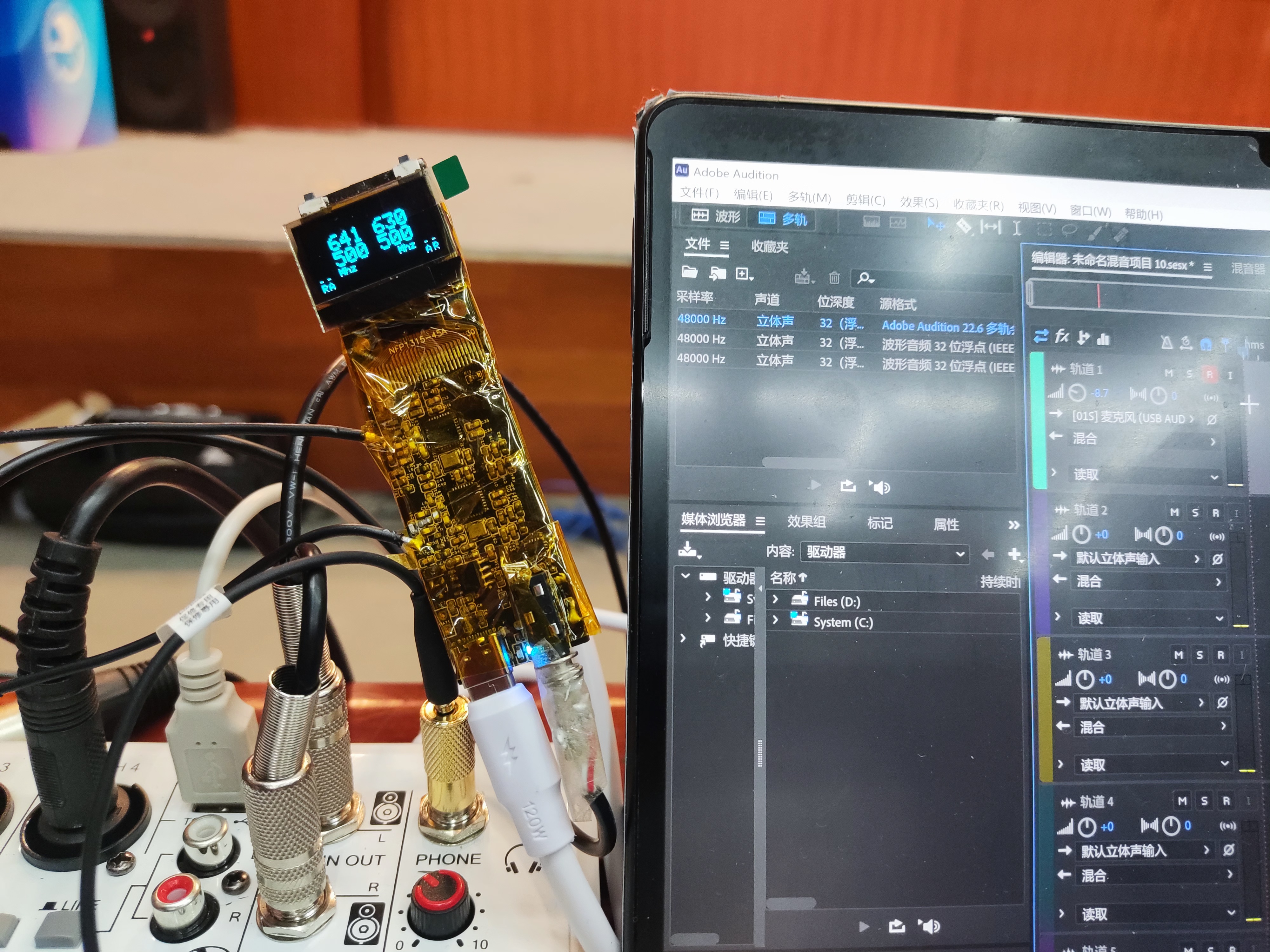
Physical demonstration & receiver version iteration history:
Because I didn't specifically take photos, the pictures are quite poor (
initially a breadboard,

then a six-layer board).
(Control board + receiver board with KT0656M chip bought from Xianyu + microphone preamp board, each two layers)
I switched to making
a single-channel KT0651 halfway through, which was the first time the noise problem was solved. Around this time, I felt I could apply for the Spark Program, otherwise I wouldn't be able to deliver a

dual-channel product. However, I was lazy and chose a double-layer board, which resulted in a lot of problems, such as introducing strange background noise

. It was the first time I used it for a performance, and the equipment was not professional at that time. Later, I bought a lot of professional equipment, and the microphone became the most unprofessional one,
with a shell added and stuffed into a pocket, which could even be used as an in-ear monitor

. During the modification of the second-layer board, I tried to install the built-in antenna in a strange way, but in the end, I used the old four-layer board and added the built-in antenna to support
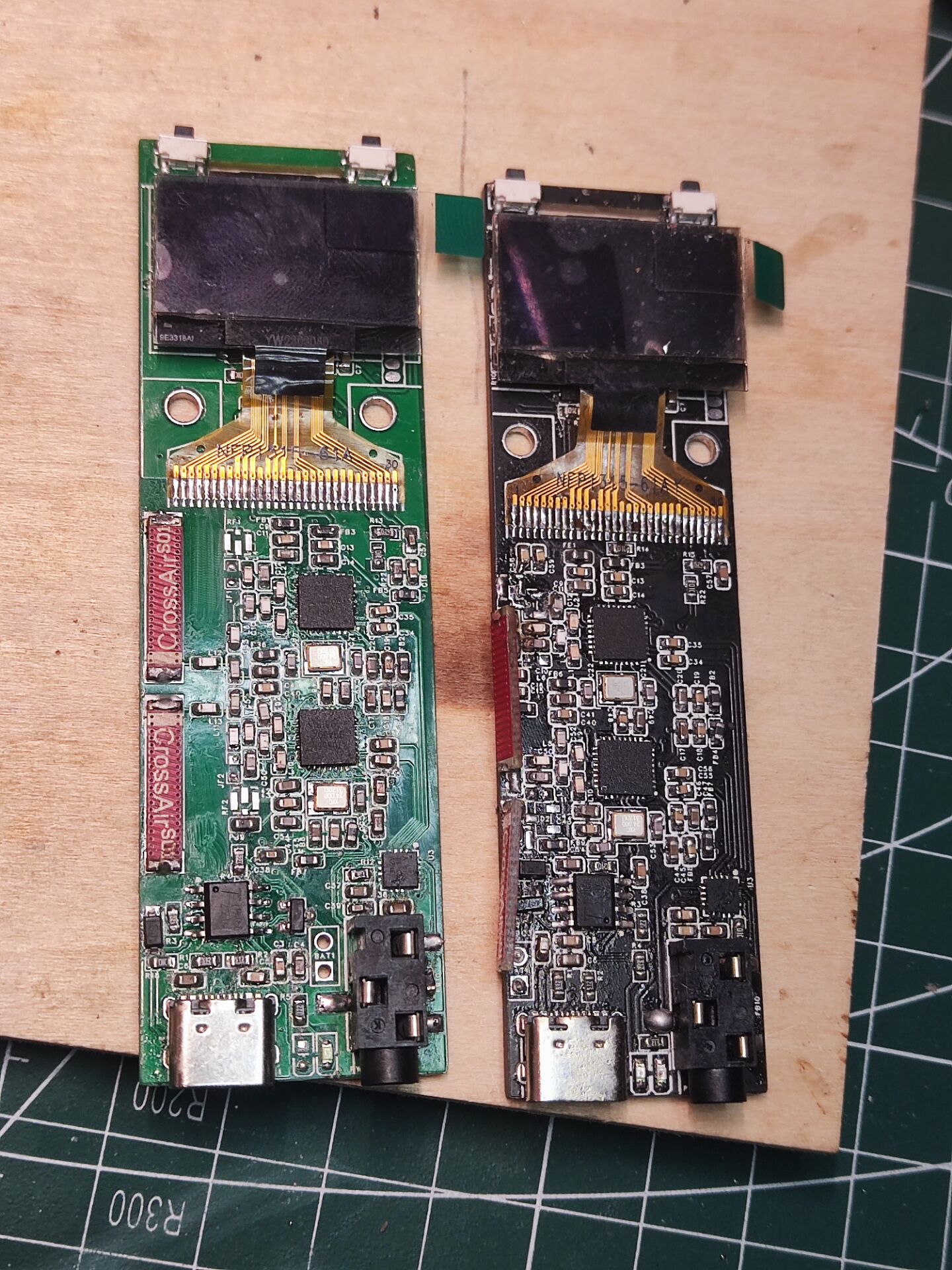
it. I tried a strange way to install the BNC connector to connect an external antenna.
This is the final version; I added BNC connector pads, and now there are three connectors: BNC, IPEX, and internal antenna. You can select one using a 0-ohm resistor
(I applied for SMT, but it hasn't arrived yet).
Other
KT06xx series chip documentation collection: https://github.com/xytoki/kt06xx.
This should be the most comprehensive collection of information currently available; finding it elsewhere usually requires payment. KT series chips have version differences, and their operation is strongly dependent on the driver code. If you encounter poor signal or poor sound quality, try changing the driver version. If you have any related materials you'd like to share, please add them to the repository. PR.
Firmware is attached.
As a final aside,
this project was basically a haphazard effort, since KT chip documentation is not publicly available. A large part of the challenges involved scraping I2C packets from existing products, guessing uncommented driver code, and copying circuit boards from existing products. However, the result was much better than expected, and I even used this setup for sound mixing at a performance, fulfilling a small aspiration I've had for microphones for so many years as an amateur sound mixer.

The board in the picture uses the KT0603 chip, which, after countless soldering attempts, had gloriously retired and was almost destroyed. The repo above contains configuration software for the 0603. A Sennheiser EW300 G2 also came with this project. The receiver and waist bag included a set of domestically produced 740-790 receivers and a waist bag, as well as several classmates who helped me solder the QFN; I would like to express my gratitude to them all. (
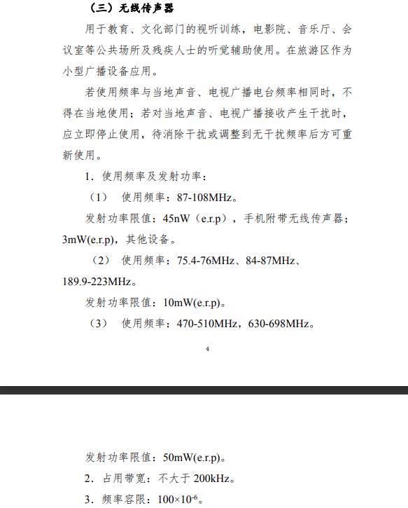
Frequency usage reminder:
700+ MHz is currently classified as broadcast 5G, and many wireless microphone devices still operate in this band. The receiver in this project was designed to receive microphones from other brands and did not have pilot mute enabled. Operating in this band may result in interference.
Additionally, theoretically, the fully compliant frequency ranges are 470-510 MHz and 630-698 MHz. Although many devices on the market operate outside these ranges, it is still recommended to use these two bands.
Regarding purchasing modified microphones:)
Microphones sold on the market now often use different chips within the same design. Besides the KT series, the BK series is also common. These two chips are completely incompatible, so be careful not to buy the wrong one.
Some vendors sell VHF microphones as UHF, or even those using 2.4G or Bluetooth. Don't buy the wrong one
either. If you ask the vendor what chip it uses, they likely won't know; they're mostly distributors. These microphones are basically rebranded.
How can you guarantee you'll get a 100% reliable product? Look for frequencies between 640.5MHz and 669.5MHz or 610.5MHz and 639.5MHz, in 1MHz steps. 99% of the solutions in this band use KT0641 (compatible with KT0646M) + KT0651. Ask the vendor for a sample, to power it on, and to record a frequency switch; most vendors can do this.
Demonstration videos
should show basic operation, transmitter and receiver pairing, and the use of two microphones in a dual-channel configuration.


 京公网安备 11010802033920号

 HDSP-315L-LG000


