Project Introduction:
As a hardware engineer, you often need to use serial ports for data reception and device debugging. When using serial-to-USB devices, you'll often encounter the question, "What is the COM port number for this device?" This can be solved by checking Device Manager, although the steps are tedious but acceptable. However, if you need to use multiple serial ports simultaneously, associating the COM port number with the hardware serial port is not easy, wasting a lot of time before debugging even begins.
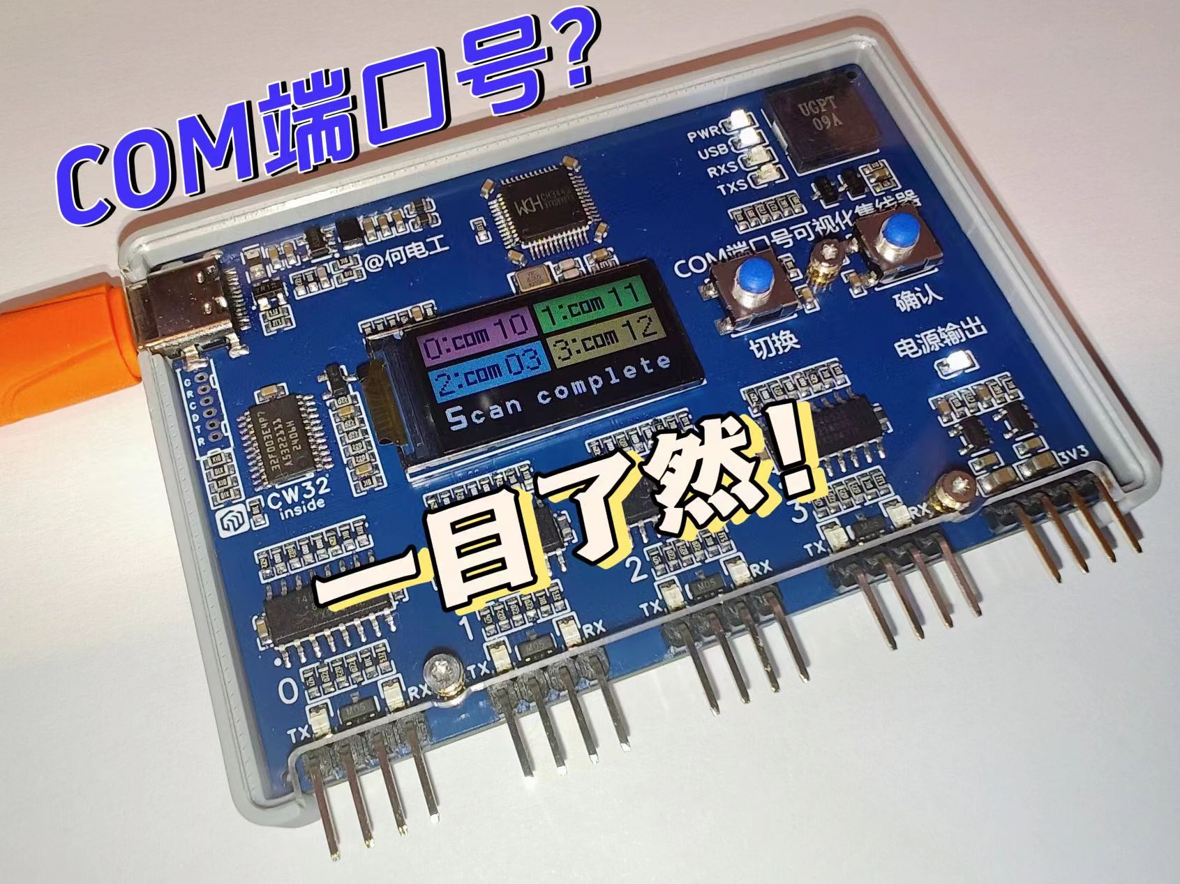
Therefore, this project was created, using a 4-to-1 serial port hub + MCU solution. Simply connect the device to the computer, and the microcontroller, in conjunction with the host computer script, will scan the serial ports and automatically display the corresponding host computer COM port number on the device, saving you valuable time.
Core Functions:
4-channel serial port hub, which can
display the computer COM port number corresponding to each external serial port via USB to 4-channel TTL serial port conversion
. It also promptly alerts the user after a USB data connection failure.
Product Instructions: COM Port Number Visual Hub Instructions
Project Video: [Open Source] Identify the COM Port Number in Five Seconds? I'll help you with
a triple like + comment to participate in the video's first release lottery! (See pinned comment in video section for details)
Welcome to follow my Bilibili account: @何电工 to learn more about interesting and practical projects.
This equipment has entered the mass production stage. You can join the exchange group to learn about the production progress. Finished products will be available for testing.
QQ exchange group: 1016193632
Open source license
CC BY-NC-SA 4.0
Creative Commons Attribution-NonCommercial-ShareAlike
Project attributes
This project is being publicly disclosed for the first time and is my original project.
This project has not won any awards in other competitions.
Hardware details
The hardware structure of this project is as follows:
CH344Q is responsible for TTL serial port to USB conversion, and MCU is responsible for communication path switching and communication with the host computer. The MCU is a general-purpose high-performance MCU from Wuhan Xinyuan Semiconductor: CW32F003E4P7.
The internal power supply of the system is from one DC-DC converter from 5V to 3V3. The external power supply comes from USB 5V and outputs 3V3 through LDO.

1. USB to serial port
The core of this project is the CH344Q chip to implement the USB to serial port function. One USB can be expanded into 4 serial ports.
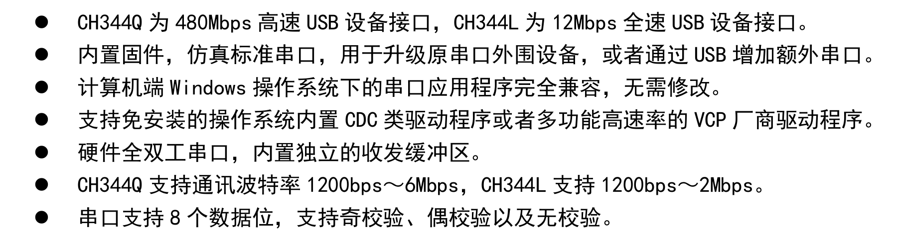
The main characteristics of the chip are as follows (screenshot from the chip datasheet):
The peripheral circuit design of the CH344Q chip is basically based on the original manufacturer's design, as follows:
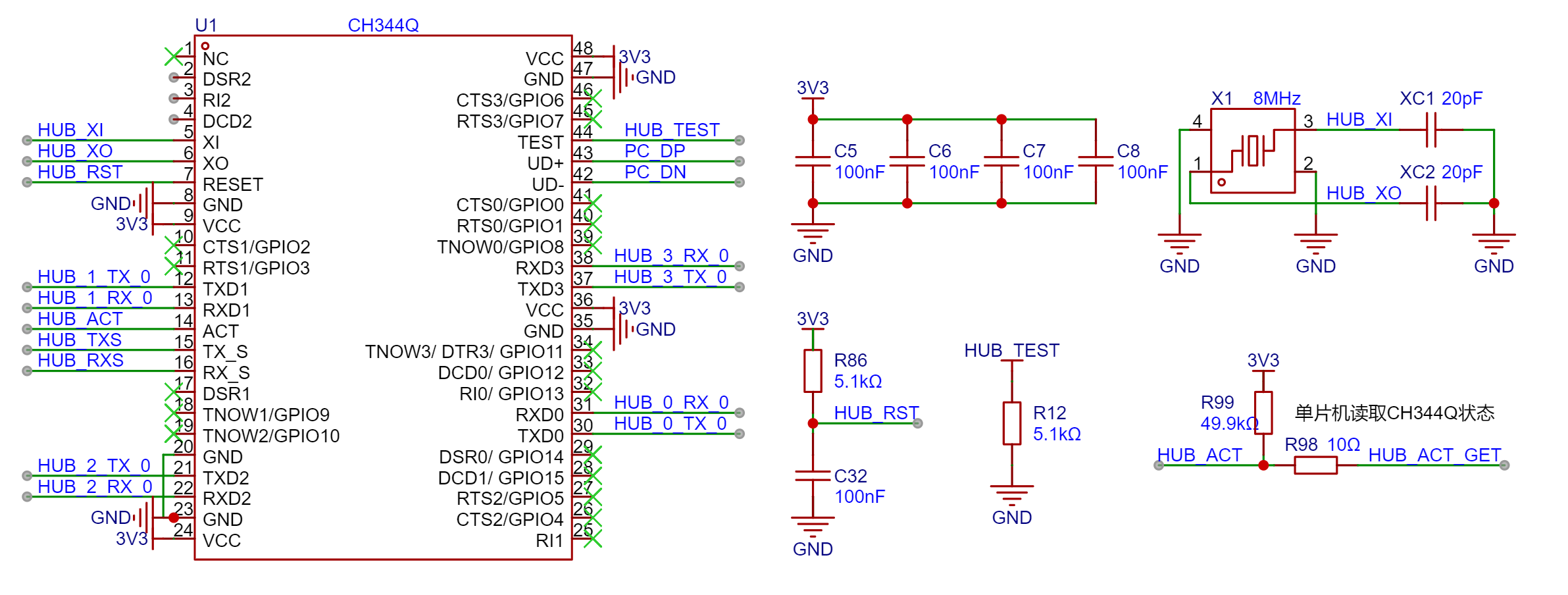
The ACT pin of the chip is used to indicate the USB connection status. When the chip is powered but communication is unsuccessful, it is at a high level (the R99 pull-up resistor is added here to avoid pin level instability during chip initialization, which may cause microcontroller recognition errors). When the chip successfully communicates, the ACT pin is at a low level. A 10Ω protection resistor is connected in series with the pin to the microcontroller pin to read the USB connection status, so that the user can be promptly notified by a buzzer if there is a USB connection error and disconnection timeout.
Serial communication rate test:
Theoretically, the serial port of this device supports a maximum baud rate of 6M. In actual testing, 4 channels can simultaneously conduct normal communication at a baud rate of 460800. Due to equipment limitations, higher speeds have not been tested.
2. Microcontroller and Peripherals:
Considering that this project may require use in complex electromagnetic environments such as industrial control/debugging, the CW32 series microcontroller, known for its strong anti-interference capabilities, was selected. Based on the project's actual requirements regarding the number of I/O channels, peripherals, and cost, the CW32F003E4P7 microcontroller was ultimately chosen.
Note: If the project requires fewer I/O channels, the CW32F003F4U7 or CW32F003F4P7 from the same series can be selected. The E4P7 has 21 I/O channels, while the F4U7 and F4P7 have 17 I/O channels; they are roughly the same in other aspects.
The CW32F003E4P7 is a general-purpose high-performance MCU from Wuhan Xinyuan Semiconductor, with an ARM® Cortex®-M0+ core and a maximum clock frequency of 48MHz.

Note: Detailed information about the MCU can be found on the official website of Wuhan Xinyuan Semiconductor: CW32F003E4P7 - Wuhan Xinyuan Semiconductor Official Website (whxy.com).
This MCU has a wide operating voltage range, from 1.65V to 5.5V, and can be directly powered by USB 5V. However, considering the need for communication with peripherals such as screens in this project, a standard 3.3V power supply is used to avoid communication compatibility issues.
This MCU has 20KB of built-in FLASH memory with a data retention period of 25 years at 85℃, 3KB of RAM, and 22 bytes of OTP memory. This project displays many pages and requires a font library for UI programming. The larger built-in FLASH memory can store more detailed fonts or even multiple font sets. Code analysis can be found in the "UI Interaction" section below.
Considering that the clock accuracy requirements of this project are relatively low, the internal RC oscillator of the CW32F003E4P7 is used as the clock source. It has multiple built-in oscillators, including 48MHz, 32kHz, 10kHz, and 150kHz. When programming, hardware timers are required for the timing-critical serial communication section, while software timers can be used for other logic sections. Code analysis can be found in the "Timing Mechanism" section below.
The MCU's communication interfaces include two low-power UARTs (supporting fractional baud rates), one for communication with the computer and the other for debugging; one 12Mbit/s SPI interface for refreshing the display; and one 1Mbit/s I2C interface (currently unused), perfectly meeting project requirements. The
debugging interface uses a 1.25mm pitch socket and is identical to those used in other projects (excluding projects before 2023), including SWD, UART, and RST pins. It is compatible with 1.25/1.27mm probe programming without soldering the debugging interface socket, facilitating mass production.
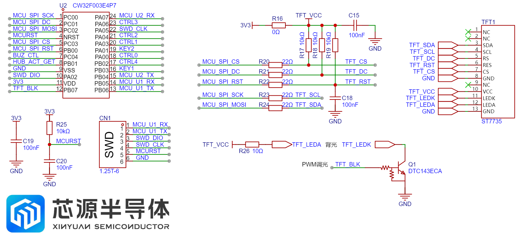
This project uses a 0.96-inch TFT color screen, communicating with the microcontroller via SPI, and employing a digital transistor for screen brightness control. Compared to the traditional transistor + MOSFET solution, the external circuitry is simpler. To reduce power consumption during device use, an automatic screen brightness adjustment is designed. The screen brightness automatically decreases one minute after the COM port number scan is complete. This "dark screen time" can be set manually, or the automatic screen-off function can be disabled.
Other peripherals of the microcontroller include two buttons and a buzzer.
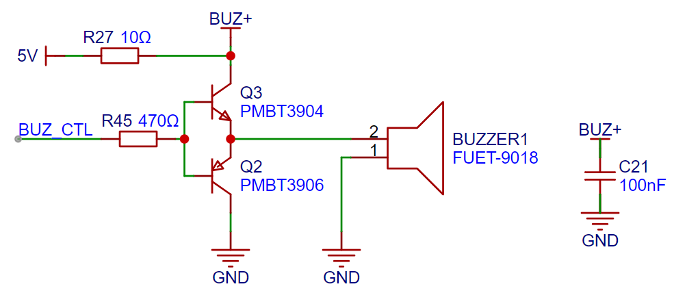
It's important to note that this project uses a piezoelectric passive buzzer. Compared to traditional electromagnetic passive buzzers, which only require a transistor to drive sound, piezoelectric buzzers require a push-pull circuit to drive them so that the piezoelectric ceramic emits sound based on the inverse piezoelectric effect. Since this project doesn't require high volume, a 5V voltage is used to drive the buzzer. If a higher volume is desired (which is a characteristic of piezoelectric buzzers), a dedicated driver circuit for boost control is needed.
3. Communication Path Switching Circuit The
communication path switching circuit is the core of this project. To better understand the implementation logic of this project, two points need to be understood first:
(1) The CW32 main control chip only controls the logic related to "communication path switching", while the "USB to TTL circuit" is controlled by CH344Q. The two services are independent of each other. Therefore, when the "communication path switching circuit" performs a switching operation, it will not affect the operation of the "USB to TTL circuit". Therefore, CW32 can use any of the serial ports of CH344Q to communicate with the host computer after switching paths.
(2) The serial port number of the microcontroller during scanning is the external serial port number. Therefore, the serial port number of the CH344Q chip is different from the external serial port number and does not affect the scanning and the final scanning result. Modifying the COM number correspondence is only to optimize the routing and avoid wire wrapping.
The following is the communication path switching circuit diagram and the communication mode truth table:

As shown in the figure above, the communication path switching circuit of the four serial ports is completely identical. Each is switched by a 4052 "double-pole four-throw" analog switch chip. The common terminal is one end of CH344, which is the HUB terminal. The A/B channels of 4052 correspond to TX/RX respectively, which is exactly a set of serial ports. The four terminals of the "four-throw" are:
00: State 0, TX and RX are grounded with 200K resistors, and the communication is in the closed state. In the early design, a 10K resistor grounding scheme was used. It was found that a set of 00 data was sent to the serial port when the 4052 was switching. During high-speed scanning, a large amount of useless data was sent to the host computer, causing interference. Therefore, it was changed to a 200K resistor to reduce the speed of the level pull-down and avoid sending useless data to avoid communication interference.
01: State 1, the TX and RX of the current channel are connected to the RX and TX pins of the microcontroller respectively, so that the microcontroller can use the "USB to TTL" function of the current channel to communicate with the host computer. (It should be noted that only one set of serial ports can communicate with the microcontroller serial port at any time, otherwise it will cause communication errors or failure to communicate.)
10: State 2, the TX and RX of the current channel are shorted with a 0Ω resistor and are in the internal loop state. However, due to the on-resistance of the 4052, there is approximately 100Ω series resistance between RX and TX when short-circuited.
In state 3, TX and RX are connected to the external interface, i.e., normal communication mode.
The 4052's state control IOs, A0 and A1, are pulled down by default, allowing the microcontroller to control them. A0 of the four 4052s is controlled uniformly, while A1 can be controlled independently. This method ensures that each serial port can communicate with the microcontroller independently while saving IOs used for state control. If an 8-channel serial hub needs to be built, a shift selector chip can be used to poll A1 and control its level.
The power
supply has two independent power supplies: a 5V-3V DC-DC power supply for internal power and a 5V and 3.3V power supply with current limiting protection for external power. The
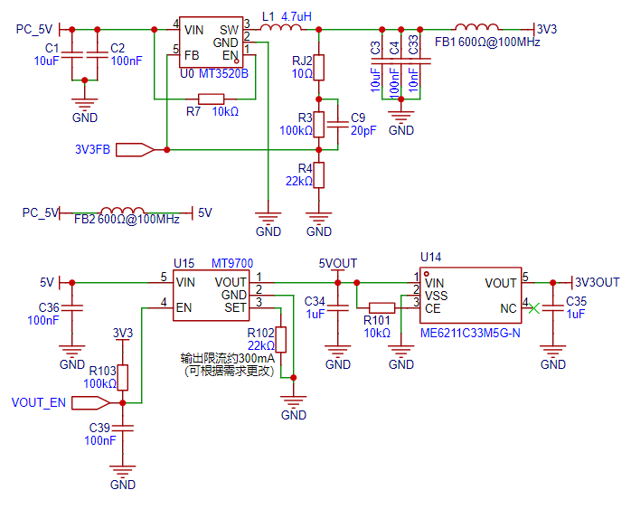
external power supply is designed with an MT9700 for 300mA current limiting protection to prevent damage to the computer in case of external device malfunction or short circuit. If the external device is overloaded, the protection will be triggered, and the "Power Output" indicator light will turn off as a warning. Most computers' USB ports have a protection current of 0.5-1A, so even if the device's external 5V is short-circuited, it won't trigger USB protection. However, some computers have a lower protection threshold, causing the USB port to enter protection mode. In this case, the USB data cable is disconnected, and you'll see the device's PWR indicator light illuminate, but the USB indicator light goes off. A buzzer will sound an alarm. In this situation, you need to disconnect the device from the computer and restart the computer for the USB port to return to normal operation.
The external power supply also includes an LDO for outputting one 3.3V output, convenient for users debugging microcontrollers and other devices. It's important to note that the 3.3VOUT upstream power supply is 5VOUT, therefore it shares the output power limit with the 5VOUT; overload of either output power supply will trigger protection.
The MT9700's enable pin uses a 3.3V pull-up resistor, combined with a large resistor to charge the capacitor and control the output enable pin, ensuring that the external power supply output time is later than the onboard device startup. The power-on timing diagram is as follows:

Channel 1 is USB power (5V), overshoot depends on the power supply device (computer) and is independent of this device; Channel 2 is 3.3V; Channel 3 is the microcontroller RST pin; Channel 4 is 5VOUT (M9700 output), the 5VOUT output time is later than the onboard device startup to ensure peripherals start in sequence.
5. External interface
devices use 90° pin headers for connection, using standard 2.54mm pitch, compatible with DuPont wires and various other common connection methods such as XH2.54mm.
The interface is equipped with a TVS diode to prevent damage from electrostatic discharge during user touch, improving device reliability.
Each serial port has independent TX and RX signal indicator lights, with TX being green and RX blue for quick identification of communication status. Each indicator light has an independent ferrite bead to prevent high-frequency interference from coupling to the power line during high-speed communication.

As shown in the diagram above, the two middle pins of each 4P header are TX and RX, while the two outer pins are GND.
This design with GND pins on both sides is to ensure compatibility with different wiring sequences and improve user experience.
The pin functions are printed on the back of the module: G=GND, T=TX, R=RX.
Software Details:
This project is based on the standard library. To conserve the main control chip's Flash memory, bare-metal programming was used, and only necessary files were imported, thus reducing the program size. The core business logic and other key code involved in this project will be explained below.
The CW32 Ecosystem Community provides rich and detailed examples and materials for the CW32 series microcontrollers. You can follow the "CW32 Ecosystem Community" WeChat official account to obtain them, or join the ecosystem community exchange group: 610403240. Several professional teachers and volunteers in the group are available to answer your questions.
Note: The lower-level machine code for this project is completely open source. You can download the "ComHubProject.zip" file from the attachment. The code has detailed comments for easy understanding.
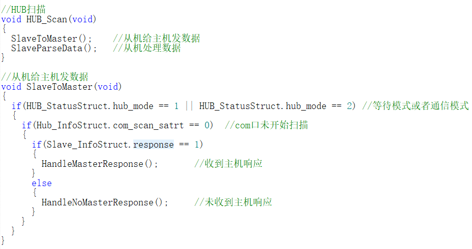
1. Master-Slave Interaction
The core of this project is to detect the COM number corresponding to the CH344 chip of the slave device by sending the COM number from the computer to the master.
The master and slave devices first establish a TCP connection and then detect the COM number via UDP. The detailed process is as follows:
(1) TCP
first handshake: After the slave device is powered on, it will automatically initialize and continuously send requests to the master to determine whether the master is online. This step ensures that the slave device knows the status of the master and prevents the slave device from wasting resources when the master is offline.
Second handshake: After the master receives the request from the slave device, it responds to the request from the slave device and notifies the slave device that the master is now online and can enter the COM port scanning stage at any time. This step confirms the connection between the master and slave devices and ensures that the slave device will enter the next stage only after the master is ready.
Third handshake: After the slave device receives the response from the master, it will first turn off the serial port receive interrupt and then send an acknowledgment message to the master device, indicating that the slave device is ready to enter the COM port scanning stage. Turning off the receive interrupt can prevent other irrelevant signals from being received in this stage, thereby avoiding interference.
(2)
After entering the COM port scanning phase, the communication mode between the master and slave devices switches to UDP, which can take advantage of UDP's high efficiency to transmit data quickly. The master continuously sends information about the four COM ports corresponding to the CH344 chip through polling, while the slave uses a timeout mechanism to determine which of the four channels corresponds to the COM ports on the computer.
(3) Communication protocol
frame header
data length
function code
data
CRC8 check
frame tail
The slave sends a COM port detection request
B5
02
01
00
XX
5B.
The master responds
A5
02
01
00
XX
5A . The
slave responds
B5
02
02
00
XX
5B.
The master polls to detect the COM port
A5
02
02.
The PC's COM port number
XX
5A.
The slave sends a communication stop signal
B5
02
03
00
XX
5B.
Although the communication content required in this project is relatively simple, it is still very necessary to use the standard communication format. This is because when the serial port polls to receive/send, an analog switch is used to ground the three unused serial ports. This will cause a falling edge signal on the RX signal line, which may cause the slave to mistakenly send a "useless" byte to the host computer. If the communication protocol is not used, this useless byte will be received by the host computer, affecting normal communication.
(4) Q&A:
① Why use TCP and UDP at the same time?
TCP reliability: In the early stage of the connection between the master and slave devices, both parties need to confirm that the other party is online and ready to communicate. TCP provides reliable connections, ensuring data integrity and transmission order. Establishing a stable TCP connection before communication begins is crucial to prevent data loss and misinterpretation.
UDP's efficiency: During the COM port detection phase, communication needs to be fast and stateless. UDP is more lightweight than TCP and lacks a complex handshake process, making it ideal for rapid data sending and receiving. Because UDP lacks a retransmission mechanism, it's better suited for scenarios where packet loss doesn't affect overall operation, such as COM port scanning where the host continuously polls and sends data, while the slave only needs to receive. In summary
, using different communication protocols at different project stages leverages the advantages of both: TCP ensures connection reliability, while UDP provides efficient data transmission.
② Why not use a two-way handshake?
Risks of a two-way handshake: With a two-way handshake, the host might begin COM port scanning before the slave is fully ready. This could lead to the slave not correctly receiving the host's scan data, resulting in misinterpretation. The third confirmation in a three-way handshake explicitly informs the slave that it is ready to perform a COM port scan, avoiding state asynchrony between the host and slave.
Slave state switching: The slave device may be processing other tasks, such as polling multiple channels, during the initial handshake. In this case, directly entering COM port scanning may lead to untimely slave state switching, further increasing the risk of misjudgment.
The three-way handshake design ensures that the master and slave devices start COM port scanning in the same state, avoiding potential synchronization problems and misjudgments.
③ Why not solve the problem with a delay?
Time uncertainty: In embedded systems, time synchronization between different devices is very difficult. Even if the master delays entering COM port scanning mode after responding, it cannot guarantee that the slave device will enter scanning mode within the same time window. This time uncertainty may lead to synchronization problems between the master and slave devices, resulting in communication errors.
Slave timeout mechanism: The slave device uses a timeout error counting mechanism in COM port detection. If the slave device enters scanning mode before the master, it may trigger the timeout mechanism while waiting for data from the master, leading to misjudgment by the slave device.
Therefore, relying on time cannot guarantee reliable communication. In contrast, the three-way handshake design can more accurately control the state synchronization of master and slave devices, ensuring reliable communication.
Summary: This design fully utilizes the reliability of TCP and the efficiency of UDP, and ensures the synchronization of the master and slave devices and the accuracy of data transmission through the three-way handshake mechanism. This design is reasonable and necessary, and can effectively avoid misjudgment and communication errors.
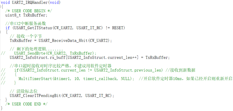
2. Serial port timeout reception
In serial communication, timeout reception is an effective method to handle the situation of incomplete data reception. The common application scenarios are as follows:
(1) Fixed length data: If the sender fails to complete the transmission of a frame of data for some reason, the receiver needs to use the timeout mechanism to determine whether the data is complete in order to avoid wasting system resources. The receiver sets a timeout value. If no more data is received within this time, it is considered that the current data frame reception has ended.
(2) Variable length data: For the case where the data length is not fixed and there is no clear frame end, it is difficult for the receiver to determine whether the data has been received completely. Through the timeout mechanism, the receiver can monitor the change of data length. If the data length remains unchanged within a certain time, it is considered that the data reception has been completed.
In this project, we experimented with the method of using software timers and hardware timers in conjunction with flag bits. Experimental results show that the combination of hardware timer and flag bit is more effective, indicating that serial port timeout reception has high precision requirements. Next, we will introduce several timing mechanisms commonly used in projects.
3. Timing Mechanism
(1) Software Timer: Software timers rely on the time base unit provided by hardware timers, such as the tick timer. It manages timed tasks based on system scheduling. Although it has high precision, it may have a slight scheduling delay due to system load. The implementation of software timers can be achieved by incrementing the global variable by 1 each time an interrupt is generated in the hardware timer, and comparing the previous count value with the current count value in the main program to determine whether the timing time has been reached. However, this method is cumbersome, and each timed task requires a flag bit. To simplify timer management, MultiTimer v2 can be used, which provides more elegant timed task management through a timeout sorted linked list. For detailed porting process, please refer to the link [MultiTimer v2 porting process].
(2) Hardware Timer and Flag Bit: The combination of hardware timer and flag bit can significantly improve timing precision. When the timer generates an interrupt, it changes the global flag bit. After the main program detects the change in the flag bit, it performs the corresponding operation. This method has high precision and is suitable for applications with strict timing requirements, such as serial port timeout reception in this project.
(3) Hardware timer output capture function: Hardware timer output capture is used for high-precision timing tasks and can be accurate to the microsecond level. When the output capture interrupt is triggered, the corresponding callback function will be executed immediately. Although the precision is extremely high, due to resource limitations, the first two timing mechanisms were used in this project to meet the timing requirements.
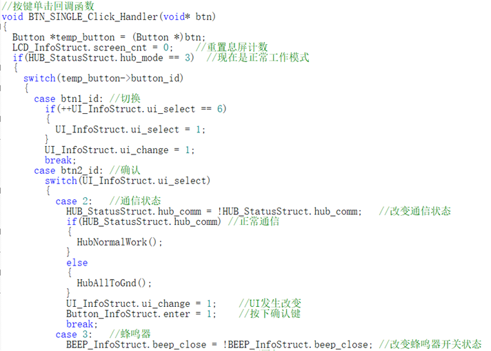
4. Button driver module
In previous projects, I usually implemented software debouncing schemes based on timers and state machines. However, in order to improve development efficiency, this time I chose a small, simple and easy-to-use event-driven button driver module - MultiButton. The MultiButton module manages button input in an event-driven manner and automatically handles debouncing and multi-button combination problems.
Compared to traditional state machine-based software debouncing solutions, this modular design simplifies code structure, reduces debugging time, and significantly improves system flexibility and reliability. Since the MultiButton module has a built-in mature debouncing algorithm and key event handling mechanism, developers no longer need to write complex code for these basic functions, allowing them to focus more on the core logic development of the project.
For a detailed porting process of the MultiButton module, please refer to the link: [MultiButton Porting Process].
5. UI Interaction
The UI display plays a core role in this project. Users ultimately learn the COM port number by viewing the screen each time they use the device. Therefore, the UI of this project has been significantly optimized, especially the font library and display.
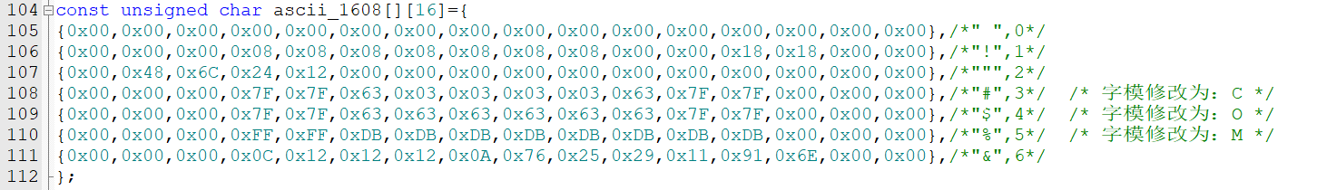
While the project superficially uses two font libraries, 1608 and 2412, these two libraries have actually undergone special processing. Therefore, this project actually includes five font libraries: a 1608 special font library (containing only the letters "C, O, M"), a 2412 numeric font library, a 2412 uppercase font library, a 2412 lowercase font library, and a 2412 symbol font library, all modeled from different computer fonts.
In this project, the fonts for the three special symbols "#¥%" in the 1608 special font library were replaced with the fonts corresponding to "COM". The remaining parts of the font library were deleted to save flash space.
Because the microcontroller uses isometric fonts, displaying very thin fonts like "i" or lowercase "L", or very wide fonts like "M" or "W", may result in poor overall visual quality. Additionally, some fine-tuning is needed for mixed uppercase and lowercase letters, and mixed English letters and numbers, to achieve better display effects. Therefore, the UI display code in this project is relatively complex.
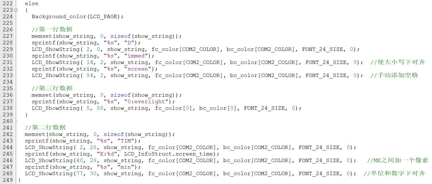
The image above is a screenshot of the UI display code, showing the fine-tuning of some character positions.
Note: This project is my first time creating a font library. Since I couldn't find a systematic tutorial, I mainly relied on self-exploration and multiple attempts. The font library isn't very good, hence the need for fine-tuning in the UI code. A new font library will be created for future projects. Once I'm proficient with the font library, I will consider creating a non-monospaced font for optimal display.
Bonus: The UI color scheme of this project references the color schemes of internationally renowned manufacturers. If you find any, please mention them in the comments section .
6. Host (Upper Computer) Detection:
The host computer is written in Python and an executable file has been generated; please download it from the attachment.
The core logic of the host computer revolves around the detection, configuration, and communication of serial port devices. The host computer program scans all serial port devices in the system, searching for serial ports whose description information contains a specified string (currently set to "CH344"). If a matching serial port is found, the program checks whether the manufacturers of these serial ports are consistent to ensure compatibility between devices and reliable communication.


After finding a matching serial port, the program configures the communication parameters and enters a polling communication loop. The host waits for the slave to send a request signal (function code 0x01). Upon receiving the request signal, it sends a response frame and clears the serial port's receive buffer. Next, the host waits for the slave to send a start signal (function code 0x02). After the start signal arrives, the host begins polling communication between the four serial ports.

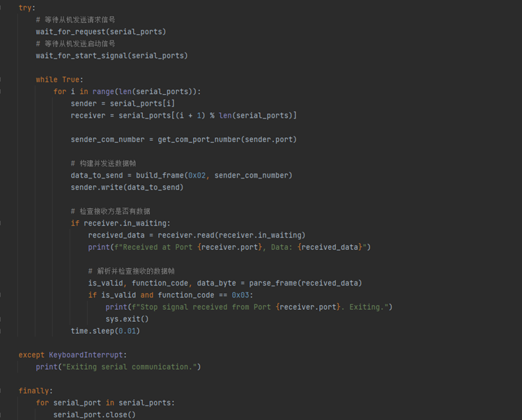
During the polling process, each serial port sequentially sends a data frame containing a function code and port number. Other serial ports receive the data and verify its validity. If the received frame contains a stop signal (function code 0x03), communication terminates and the program exits. Throughout the process, the CRC8 checksum algorithm ensures data integrity.
This logical design enables the program to effectively manage communication between multiple serial port devices, ensuring the accuracy and consistency of data transmission.
Project Replication Notes:
1. 3D printing is recommended for the outer shell. The top panel is recommended to be laser-cut from acrylic with a thickness of 1.8mm. The 3D files and acrylic cutting DXF files required for the project are in the project attachments; please download them yourself. Note: Many Taobao shops label acrylic as 2mm thick, but the actual thickness is 1.8-1.9mm. Please contact customer service for confirmation.
2. When replicating a project, it is recommended to use a probe for programming. If a test socket is soldered, it needs to be removed before installing the equipment housing. When removing it, you can first use needle-nose pliers to pull out the plastic housing of the socket, and then remove or cut the connecting pins one by one. Otherwise, the test interface socket will cause structural interference with the acrylic panel on the top panel.
3. Special components and structural parts procurement links, please note the specifications: (Not an advertisement, for reference only)
Silicone Buttons Category: 5.2H Note: The project selected the "TS-1158UB-CD-BL" button with a height of 5mm because this is the tallest silicone button available in the LCSC online store. For better feel when replicating, it is recommended to use a
0.96 TFT display with a head height of 5.2 or 5.5. Category: BOE Welded Glue-Iron Integrated
M2 Support Copper Pillar Category: M2*2.5*3
Top Plate Small Head Screw Category: M2*3.5*3 Head Diameter
Bottom Plate Countersunk Screw Category: M2*5 Blackened
4. There are six round holes on the PCB, three of which are M2 screw fixing holes with a diameter of 2.1mm. The two diagonal holes on the PCB are 1.152mm special positioning holes for economic SMT. If economic SMT is not used, the positioning holes can be deleted and copper re-laid according to the actual situation. The CH344Q chip used

in
this project natively supports RS232/485. If you have no need for TTL serial ports, you can directly modify the motherboard to support RS232/485 communication without using an expansion board.
Based on the current hardware and software version, one computer can only connect to one visual serial port hub. If there is a large demand for "more serial ports" in the future, a USB to 8-port serial port version may be released (procrastination), so please join the group to urge for updates.
For any questions or suggestions regarding the project or the replication process, please join my discussion group!
QQ Group: 1016193632.

Project Video: [Open Source] Identify the COM port number used in five seconds? I'll help you with
a triple like + comment to participate in the video's first release lottery! (See the pinned comment section for details)
Acknowledgements
Special thanks to LCSC Open Source Hardware Platform and the CW32 ecosystem community for their support of this project!
Special thanks to aiapp-isp software, a very useful font extraction software!
Special thanks to the following friends for their help and contributions to this project in their respective fields:
Software: @C_P
; Imaging: @Mr. Geng Studio;
Testing: @Qinxian.
Thank you again to all the friends who answered my questions during the project design and debugging process!


 京公网安备 11010802033920号

 JANTXV1N2827RC


