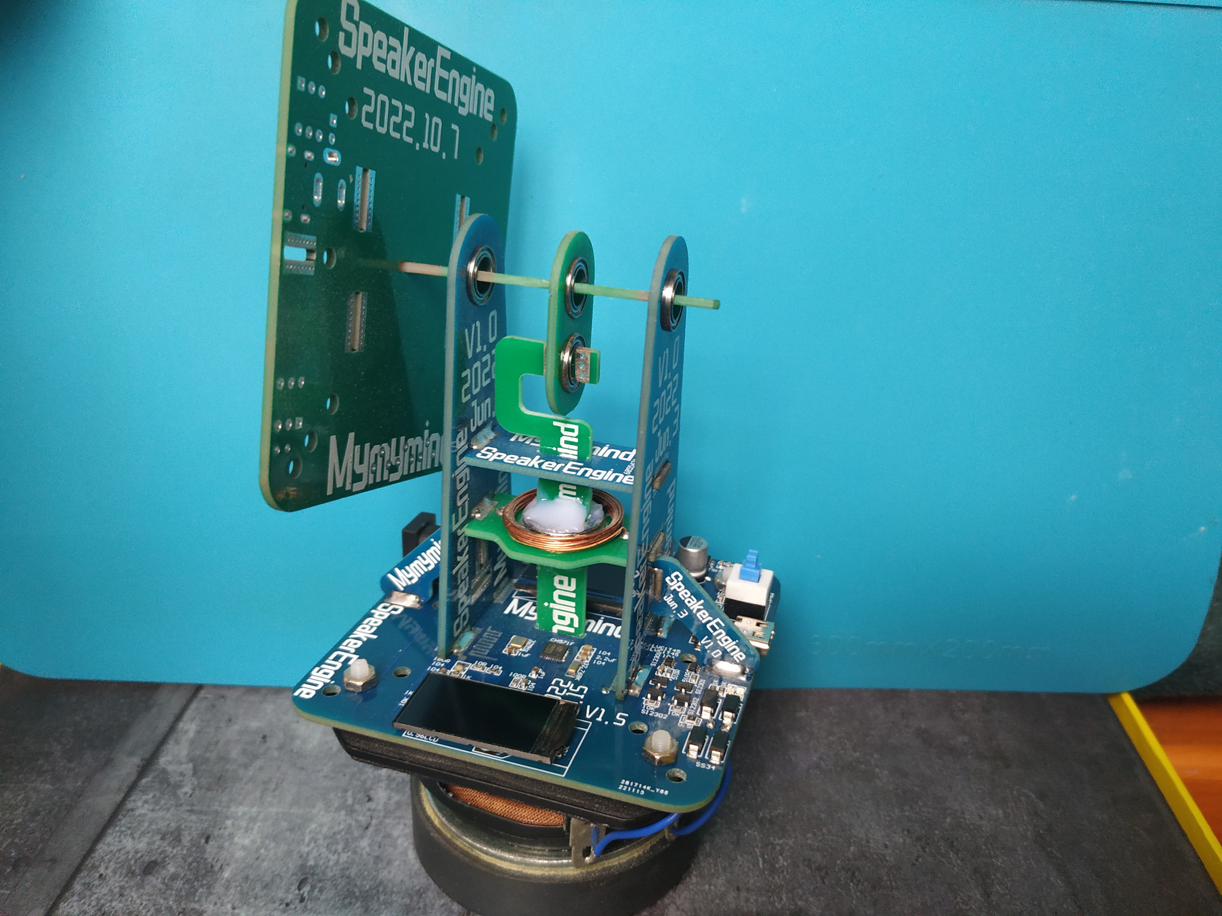
The Horn Engine V1.0 uses a 4Ω 5W full-range horn as its power source.
The engine frame is built using a PCB structure. The horn's vibration drives the connecting rod and crankshaft, which in turn rotates the flywheel.
Screen 2: 160*80 TFT.
Video Introduction: https://www.bilibili.com/video/BV1jR4y1Z7df (Demonstration Video)
The K60 basic function motherboard, specifically designed for intelligent vehicle course design,
includes features such as a camera, electromagnetic induction generator, encoder, and wireless serial port, serving students involved in intelligent vehicle course design projects.
This is the main control board for a full-heat-air coffee roaster, suitable for DIY use. It features
two temperature acquisition channels using a MAX6675 K-type thermocouple
wirelessly connected to an Artisan controller, providing
0-10V output control for the SCR and PWM brushless fan.
This is a main control board for a full-heat-air coffee roaster, suitable for DIY use. It features two temperature acquisition channels: BT and Inlet, using a MAX6675 K-type thermocouple for wireless connection to an Artisan 0-10V output to control a SCR fan using 12/24V brushless control. An I2C interface is provided for connecting extended sensors, OLEDs, etc. The current open-source board program functions as follows: 1. Wireless connection to Artisan to record temperature data; 2. Manual control of fan and heating power. **
Important Note:** The K-type thermocouple's temperature linearity is only suitable for general use… If possible, use a PT100/PT1000; using a SCR for heating power output is less damaging to the heating wire than a PWM signal, and the price difference in controllers is minimal. For DIY, please use reputable brands; for other software functions, please contact me privately [grinning face emoji]. This
is an open-source project; no technical support is provided. Please participate based on your own development conditions and experience.
Firmware open-source address:
https://gitee.com/sakunamary/Roaster_controller_opensource
Operation video references:
1. https://www.bilibili.com/video/BV1eg411e7H4/ (How to connect the module to Wi-Fi)
2. https://www.bilibili.com/video/BV1et4y1w7i5/ (How to connect to Artisan)
3. https://www.bilibili.com/video/BV1AV4y1L7yL/ (Basic Artisan operations)
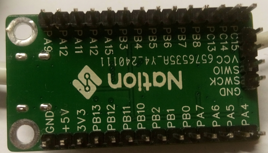
Guoming Technology's MCU, model N32G030C8
:

Front and back views
V40528-180802[1].mp4
PDF_Guoming Technology-N32G030C8-Core Board.zip
Altium_National Name Technology-N32G030C8-Core Board.zip
PADS_Guoming Technology-N32G030C8-Core Board.zip
94518
Outdoor Smart Compass
Based on ESP32S3 outdoor smart compass
First of all, thank you to LCSC for hosting this summer fun event (I can get free coupons again, haha!).
In the wave of modern outdoor adventure, an advanced smart outdoor compass is undoubtedly an indispensable assistant for explorers. This smart compass combines cutting-edge technology with user-friendly design, providing explorers with accurate and convenient directional guidance, making every outdoor trip safer and more efficient.
This smart outdoor compass uses a high-precision gyroscope and magnetic sensor, which can sense changes in the Earth's magnetic field in real time, providing accurate directional indications even in complex geographical environments. It helps explorers quickly plan routes and avoid getting lost.
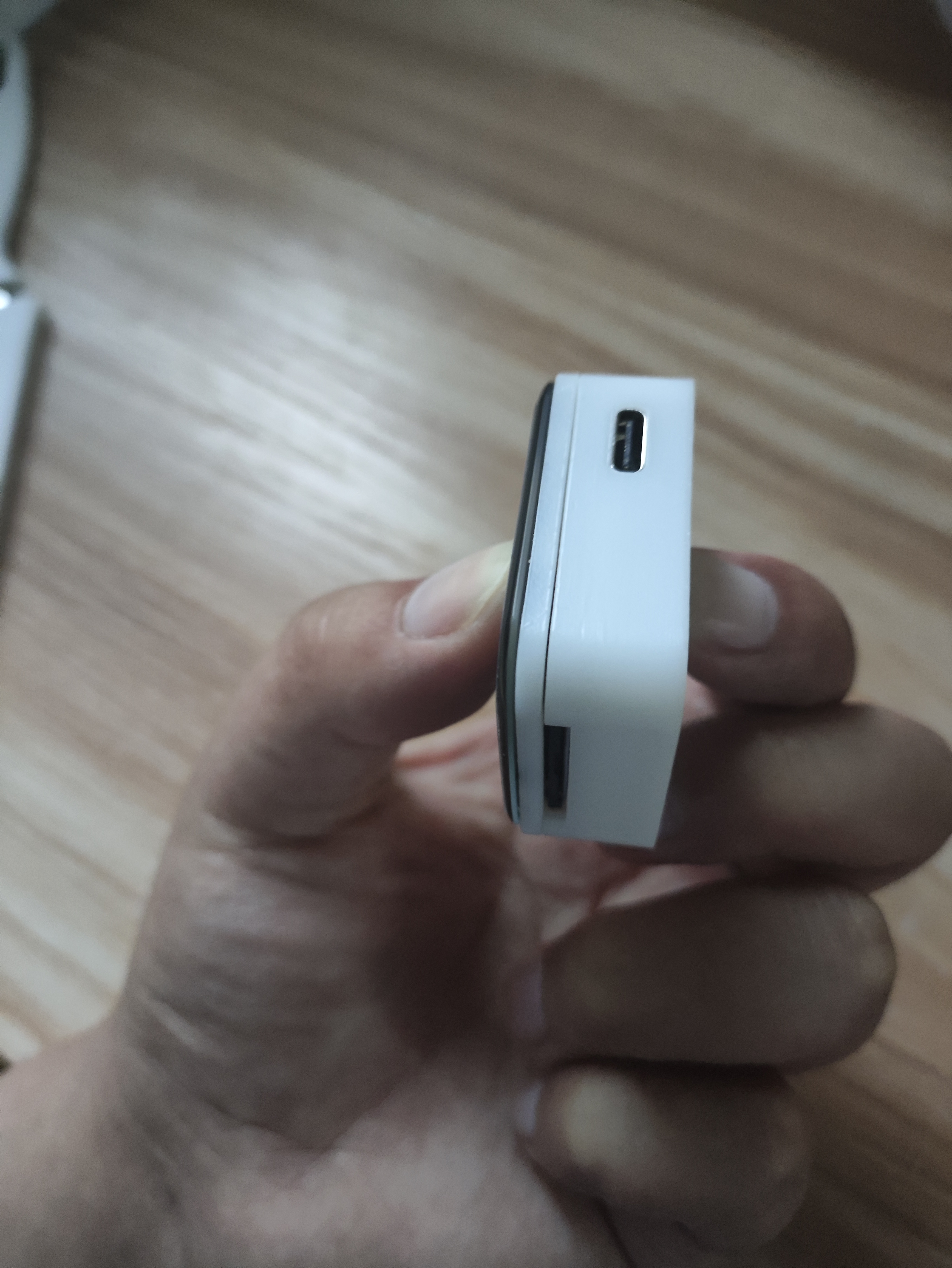
The smart compass has a simple and elegant design, made of lightweight materials, making it easy to carry and easily attached to a backpack or belt. Its display uses high-definition touch technology, which is clearly visible even in strong light. The interface layout is intuitive and user-friendly, allowing explorers to easily operate various functions.
In addition to basic directional guidance, this smart compass also has a variety of practical features.
In terms of battery life, this smart outdoor compass performs excellently. It uses a high-capacity lithium battery, supporting long standby and continuous use.
1. Hardware Design
: The main controller uses an ESP32S3R8, the sensor is a QMC5883L, and the screen is a 1.69-inch touchscreen from Puyang. A TP4056 is used to charge the lithium battery; since the battery has its own protection board, no additional protection circuitry is used.
It supports automatic power supply and USB switching, and uses an LDO to 3.3V converter. Currently, the LDO is getting quite hot; I'll try replacing it with a dedicated power management chip when I have time. A 0.5mm 30-pin connector is used to bring out the GPIO for easy expansion of future functions.
The programming process uses the ESP32S3's USB port without additional soldered headers, limiting the layout. The board is relatively simple, the design is so-so, but it works, haha.
2. Soldering:
The most difficult part of the soldering process is the ESP32S3; everything else is fine. I used a hot air gun. You can preheat the board first, then apply solder paste (a little extra is fine), then blow the solder out; it will come out on its own. Finally, apply some flux and use a soldering iron to smooth it out.
Just be careful about the temperature of that screen holder, otherwise it will easily melt.

3.
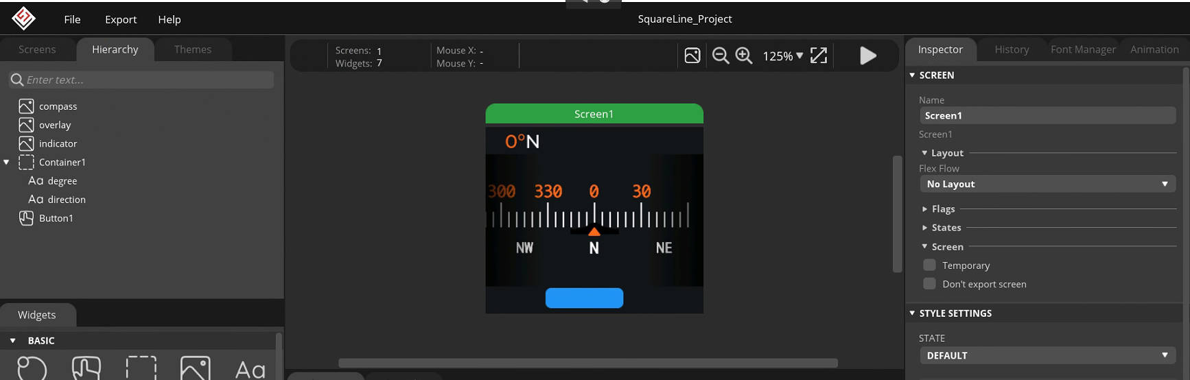
All the software development code is on GitHub. It is developed using IDF. The screen driver is ST7789V+CST816S, which is very common. The page is LVGL. The UI is based on a YouTuber's work (I have no aesthetic sense, haha).
wx-dev/esp32s3-idf-watch (github.com)
The geomagnetic sensor uses QMC5883L
to read the sensor
void qmc5883l_read_xyz(t_sQMC5883L *p) { uint8_t status, data_ready = 0; int16_t mag_reg[3];
qmc5883L_register_read(QMC5883L_STATUS, &status, 1); // Read the status register
if (status & 0x01) { data_ready = 1; } if (data_ready == 1) { data_ready = 0; qmc5883L_register_read(QMC5883L_XOUT_L, (uint8_t *) mag_reg, 6);
p->mag_x = mag_reg[0]; p->mag_y = mag_reg[1]; p->mag_z = mag_reg[2]; }}
calibrate geomagnetic sensor
void calibrateMag(){ int x,y,z; // triaxial data int xMax, xMin, yMax, yMin, zMax, zMin; // initialization t_sQMC5883L p; qmc5883l_read_xyz(&p); xMax=xMin=x=p.mag_x; yMax=yMin=y=p.mag_y; zMax=zMin=z=p.mag_z; offsetX = offsetY = offsetZ = 0; for(int i=0;i { qmc5883l_read_xyz(&p); x=p.mag_x; y=p.mag_y; z=p.mag_z; // Calculate maximum and minimum values // Calculate the maximum and minimum magnetic field strength of the sensor when it rotates around the X, Y, and Z axes if (x > xMax) xMax = x; if (x xMin = x; if(y > yMax ) yMax = y; if(y yMin = y; if(z > zMax ) zMax = z; if(z zMin = z; vTaskDelay(100 / portTICK_PERIOD_MS); } // Calculate correction amount if (abs(xMax - xMin) > CalThreshold) offsetX = (xMax + xMin) / 2; if (abs(yMax - yMin) > CalThreshold) offsetY = (yMax + yMin) / 2; if (abs(zMax - zMin) > CalThreshold) offsetZ = (zMax + zMin) / 2; ESP_LOGI(TAG, "offsetX = %d offsetY = %d offsetZ = %d ", offsetX, offsetY, offsetZ); vTaskDelay(5000 / portTICK_PERIOD_MS);}
Calculate the angle value.
void qmc5883l_fetch_azimuth(t_sQMC5883L *p) { qmc5883l_read_xyz(p); float headingRadians = atan2((double)((p->mag_y)-offsetY),(double)((p->mag_x)-offsetX)); // Ensure data is between 0 and 2 * PI if (headingRadians headingRadians += 2 * M_PI; } int headingDegrees = headingRadians * 180 / M_PI; headingDegrees += -5; // Magnetic declination // Ensure data is between 0 and 360 if (headingDegrees > 360) { headingDegrees -= 360; } p->azimuth = (float) Currently, calibration has been added ,
but the accuracy still seems unsatisfactory, especially after switching from the xY axis to the xZ axis. I'm unsure if this is a sensor or code issue.
Page Design
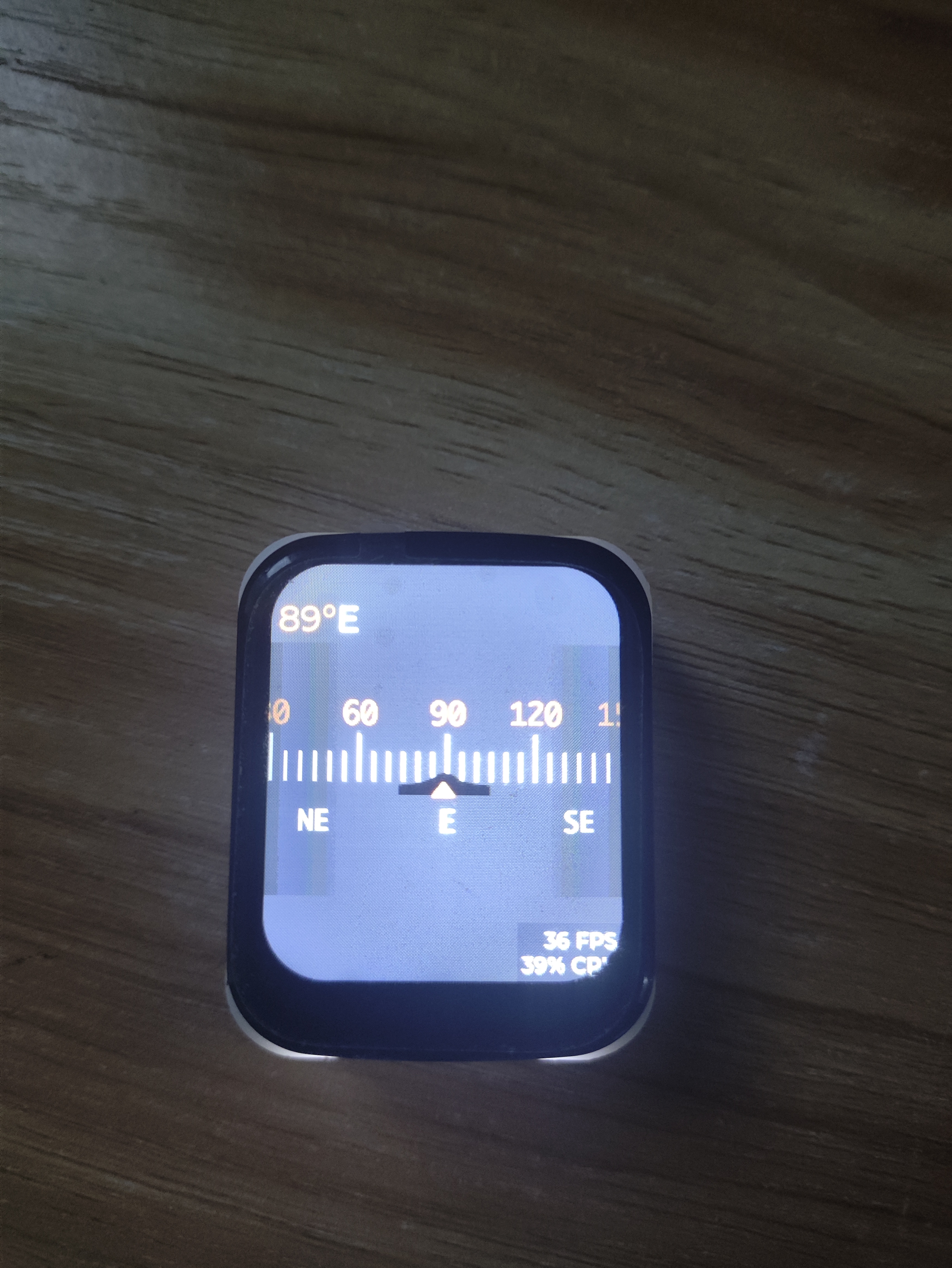
4. Testing:
Currently, the geomagnetic data is being read normally without major problems; the only issue is the slightly poor accuracy. Further optimization is needed. Regarding hardware, the lack of a dedicated power management chip causes the board to get a bit hot.
Later, with the addition of an attitude sensor and temperature/humidity sensor, it will become a more advanced device and can even be used as a development board! Haha.
5. Finished Product Showcase
VID_20240528_185901.mp4
Test video.mp4
PDF_Outdoor Smart Compass.zip
Altium_Outdoor Smart Compass.zip
PADS_Outdoor Smart Compass.zip
BOM_Outdoor Smart Compass.xlsx
94520
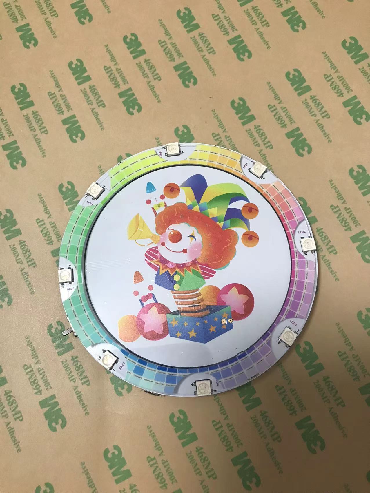
Electronic Fools - Magic Mirror
Activate the magic mirror with your voice, answer questions, and experience the iridescent LED rendering effect.
*Coo-coo* This project has been delayed again and again, but the first version is finally being released. The main reason was that the outer shell wasn't finished. Ultimately... the outer shell still wasn't finished.

I. Material Introduction
1. Uses the Qiying Tailun voice module, which is cost-effective and has good playability
. 2. Uses 8 WS2812B LEDs for effect rendering
. 3. The outer shell is 3D printed (to be added in the second version).
4. The panel is printed to cover the circuit, and the LED section has a transparent window
. 5. Battery (to be added in the second version)
. 6. Includes a switch and a USB power port.
II. How to Use
1. Insert the USB cable for power; the second version will use a battery.
2. Turn on the switch; the module will initialize with a voice prompt.
3. Voice reference video; you can develop questions and answers according to your preferences.
III. Software Development
Firmware and source code are attached.
1. Reference document:
https://document.chipintelli.com/%E8%BD%AF%E4%BB%B6%E5%BC%80%E5%8F%91/SDK/CI112X%E8%8A%AF%E7%89%87SDK/start/CI112X_SDK_Quick_Start/
2. Firmware creation process overview:
2.1 Create a language model, during which an acoustic model is downloaded and placed in the dnn folder.
2.2 The language model can be generated online or by uploading a list. After editing the list, the language model is generated and downloaded.
2.3 The language model contains a readme; place it in the user_file and asr folders as required.
2.4 Create the broadcast tone, which can be generated online or by uploading a list. After editing the list, the broadcast tone is generated.
3. Software development tool:
Link: https://pan.baidu.com/s/1_ysKJ9rSXCpH-XAoLpLChw Extraction code: 2iy2
4. The code reference
is based on https://github.com/DawningW/VoiceLamp and modified.
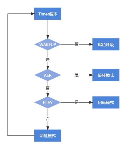
The `rgb_timer_handler` in `light_rgb` refreshes every 50ms, checking the following conditions to switch modes (default is idle)
: 1. `get_wakeup_state`: Enters UNWAKEUP (sleep mode), sets mode to dark vibrant.
2. `get_wakeup_state`: Enters WAKEUP (wake-up mode), continues checking.
3. `get_asr_state`: Enters SYS_STATE_ASR_BUSY or SYS_STATE_ASR_SUSPEND (recognition in progress), sets rotation
. 4. `get_asr_state`: Enters SYS_STATE_ASR_IDLE (recognition complete), sets idle mode to bright vibrant
. 5. `get_audio_play_state`: Enters AUDIO_PLAY_STATE_START, AUDIO_PLAY_STATE_PLAYING, or AUDIO_PLAY_STATE_STOP (playback state), sets blink mode
. 6. ... `get_audio_play_state` enters `AUDIO_PLAY_STATE_IDLE`, i.e., the static state, setting highlight and color effects
. In addition, the NV saving and reading parts have been removed, and bugs have been fixed.
------------------
Second Version Improvement Plan
------------------
Usage Expansion
1. Question-Answer Mode (Implemented)
The "Magic Mirror" voice wake-up module responds to questions like "Who
is the most beautiful person in the world?". For example, who is the most beautiful person in the world? The answer is the person in the mirror.
Who is the richest person in the world? The answer is the person outside the mirror. And so on.
2. Entertainment Mode (To be Implemented)
8 iridescent LEDs represent 8 directions, which can be used for dice or to emit rainbow changes when the Magic Mirror is woken up.
3. Beauty Mode (To be Implemented)
8 iridescent LEDs can adjust color brightness according to direction, or by voice, saying "start" or "stop".
Hardware Expansion
1. Add a battery for handheld play anytime.
2. Add a mirror effect; further consideration needed, including the reflective material of the panel
. 3. Complete and decorate the casing
. 4. Reduce the size of the microphone and speaker.
Firmware_V100.bin
demo.mp4
mojing-master.zip
VoiceLamp-master.7z
PDF_Electronic Fool's Fun - Magic Mirror.zip
Altium_Electronic Fooling-Magic Mirror.zip
PADS_Electronic Fool's Fun - Magic Mirror.zip
BOM_Electronic Fools-Magic Mirror.xlsx
94521
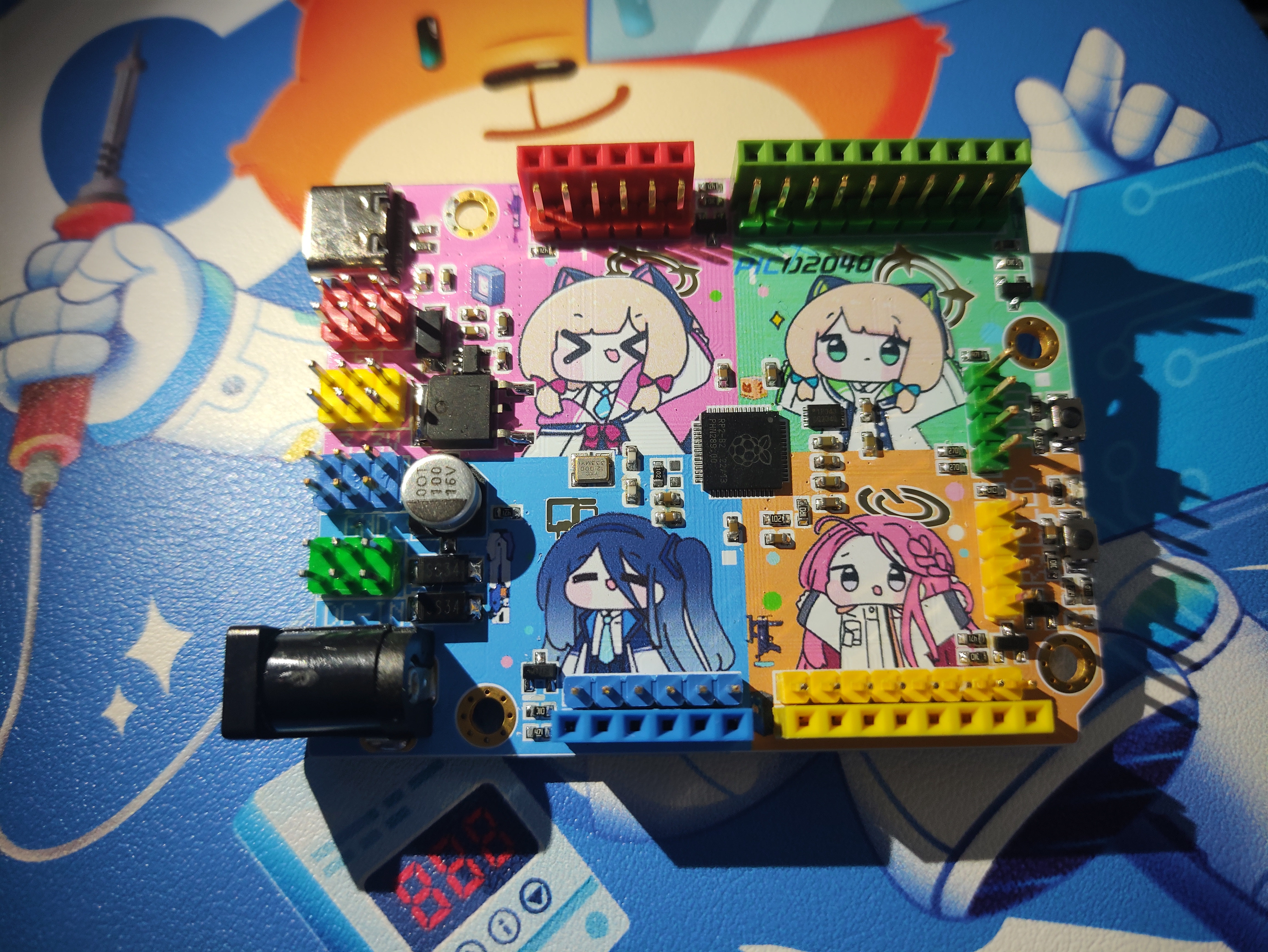
【Azure Archives】 RP2040 Color Screen Printing Board
This is a modified version of __Aknice's project,
which has been verified (only part of the power supply was modified, and all resistors and capacitors were changed to 0603).
It has the same functionality as the original work.
This is a modified version of the project by __Aknice. Without further ado, here's the project: 【Azure Archives】Raspberry Pi RP2040 Color Silkscreen Development Board - JLCPCB EDA Open Source Hardware Platform (oshwhub.com).
My modified version is the public beta version from JLCPCB, so you can ignore it. Although it warns of potential issues, it works without problems in practice. You can use the new version files with the old version.
The schematic is the same; I just changed the DC-DC converter to an LDO L7805 and replaced all resistors and capacitors with 0603 capacitors. Refer to the schematic for details.
Other useful projects (also on the homepage) are as follows:
Album Details Page - JLCPCB EDA Open Source Hardware Platform (oshwhub.com)
WeChat_20240514110339.mp4
PDF_【Azure Archives】RP2040 Color Silk Screen Printing Plate.zip
Altium_【Azure Archives】 RP2040 Color Screen Printing Plate.zip
PADS_【Azure Archives】RP2040 Color Screen Printing Plate.zip
BOM_【Azure Archives】RP2040 Color Screen Printing Board.xlsx
94522
hangar control panel
The board used to control the helipad is an STM32F407VET6, equipped with various peripherals.
The board used to control the helipad is an STM32F407VET6, equipped with various peripherals.
PDF_Hanger Control Panel.zip
Altium_Hanger Control Board.zip
PADS_Hanger Control Board.zip
BOM_Hangar Control Panel.xlsx
94523
Small fan based on ESP8266
Small fan based on ESP8266
Project Overview: Users can control the fan's on/off state, speed, and timer function via control buttons and modules.
Hardware Components: ESP8266 Module - for Wi-Fi connectivity and control logic. DC Motor - the main component of the fan. Motor Drive Module - controls the motor's speed and direction. Power Supply Module - provides a stable power supply to the ESP8266 and motor. Resistors and Capacitors - for circuit stability and protection. Housing - for securing and protecting components. Software Components: Arduino IDE - for writing and uploading code to the ESP8266. Web Server - runs on the ESP8266 and handles requests from clients. Control Interface - can be a web page or mobile application for sending control commands. Safety and Stability: Overload Protection - Overload protection mechanisms are included in the circuit to prevent motor overload. Power Management - Ensures the power supply module provides a stable and compliant power supply. Error Handling - Error handling mechanisms are included in the software to ensure stable system operation. Debugging and Testing: Unit Testing - Individual testing of each module to ensure proper functioning. Integration Testing - Integrating all modules together to test the entire system's operation. Performance Testing - Test the system's performance under different conditions, such as temperature and humidity. User Interface: Simple and Intuitive - The control interface is designed to be simple, easy for users to understand and operate. Responsive Design - The interface adapts to different devices, such as mobile phones and tablets. Maintenance and Firmware Upgrades - Provide firmware upgrade functionality to fix bugs or add new features. User Feedback - Collect user feedback to continuously optimize the product. This engineering description provides a basic framework; specific implementation details will be adjusted according to actual design and requirements.

17d353db1dc33e58dce4bd5fb151b19.jpg
4e718ce5f4cf63adf406373e38049aca.mp4
PDF_Small Fan Based on ESP8266.zip
Altium_Small Fan Based on ESP8266.zip
PADS_Small Fan Based on ESP8266.zip
BOM_Small Fan Based on ESP8266.xlsx
94524
electronic


 京公网安备 11010802033920号

 TC9135P


