This project
introduces a pulse wave display using a PulseSensor as the heart rate sensor. Utilizing the PPG principle, green light is shone onto the skin surface (usually a finger), and a photoelectric sensor detects the intensity of the reflected green light. The intensity change curve represents the pulse curve. For convenience, a heart rate module is used to amplify the signal and fix the signal value near half the power supply voltage for easier reading.

Open Source License:
CERN Open Hardware License.
Features:
Pulse waveform display ,
heart rate display,
three-color pulse indicator, breathing light
, pulse beep,
multiple interface options.
Project Attributes
: This is the first public release of this project; it is my original work. This project has not won any awards in other competitions.
Project Progress
: 2024-04-03 Project Initiation
2024-04-06 Schematic and PCB Design Completed
2024-04-20 Added Function Buttons for Switching Interfaces
2024-04-24 Shell Design Completed
2024-04-28 Panel Design Completed
2024-05-11 Panel Improvement, Display Area Increased by 1mm
2024-06-01 Software Development Completed
2024-08-26 Data Compilation Completed, Open Source Project Released
Hardware Design
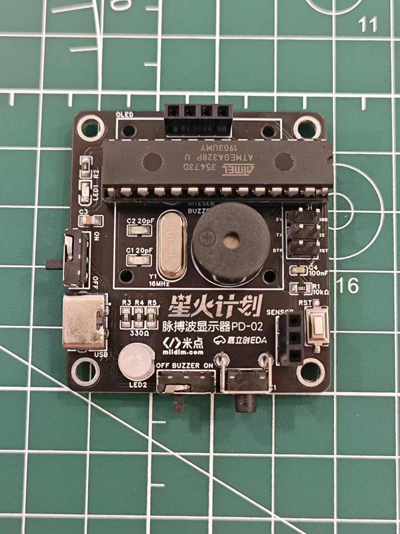
MCU Uses ATMEGA328P-PU, Arduino UNO R3 Main Controller. Because the project was a replication and improvement of a foreign open source project, and I had just completed an oscilloscope training camp at the time, my knowledge was insufficient, so I could only use the original hardware design. I will continue to improve the design and choose a more cost-effective MCU when I have the opportunity.
The power supply section uses a Type-C 2P power supply. A lithium battery and power management chip could be considered for future upgrades to improve portability.
The display uses a 0.96-inch white OLED with a header and socket connection, allowing for easy removal and reuse in other projects.
The buttons are used for cycling through the display interface.
The program download section only has a reserved interface and does not have a built-in serial port chip; a serial port download tool is required for program download. An automatic program download can be achieved using a programmer with a DTR pin.
The LED section uses a three-color RGB LED fog light.
The buzzer section uses an active buzzer that only needs a high-level output to produce sound. Previously, a passive buzzer was used, requiring PWM drive. Testing revealed conflicts with other timers, causing sound distortion. Various methods were tried without success, presumably related to MCU performance; therefore, an active buzzer was used instead. A buzzer switch is also included, allowing the sound to be turned off independently. The software
design
is relatively simple. The heart rate sensor outputs an analog signal. Data is acquired via an ADC, processed by the PulseSensorPlayground official library to obtain the heart rate, and the waveform is processed to suit the screen display. Finally, it is displayed on the screen via the I2C protocol. The lighting section illuminates different colored LEDs according to different heart rate zones. The buzzer sounds each time a heartbeat is detected. Pressing a button triggers an interrupt and changes the mode. The OLED then displays different interfaces depending on the mode.
Physical
demonstration: [Image of physical model
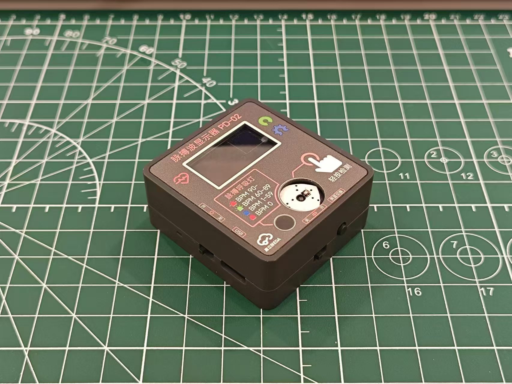
without screen and heart rate sensor
assembly structure]

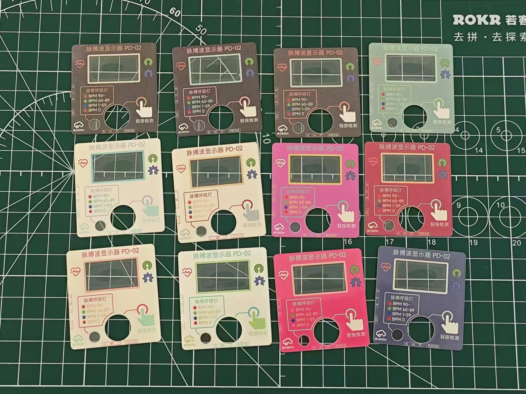
Panel
color scheme reference: Xiaohongshu @YUI_Design, https://www.xiaohongshu.com/user/profile/640eee95000000000f0105c8
Cost estimate:
Material
price:
PCB
(free)
, OLED
8.4 ,
Heart rate sensor
7.8,
ATMEGA328P
10,
Buzzer
0.6,
RGB LED
0.2
16MHz crystal oscillator
0.3 ,
resistors and capacitors
0.2,
pin headers and nuts
0.5,
screws and copper pillars
1 ,
switch
0.6,
LED
0.1,
Type-C female connector
0.1 ,
panel
1.3,
housing
14.43
, total
45.53.
Note: The above prices are unit prices and do not include shipping.
The panel needs to be ordered as a whole piece (300mm*200mm), priced at around 30. A total of 24 pieces can be cut, so the unit price is around 1.3.
If a panel is not needed, the outer shell can be modified by removing the top recessed area.
Replica Notes:
1. PCB
thickness : 1.6mm
2. 3D printed
outer shell material: Black;
support column material: LEDO6060
3. Panel:
Panel type: film panel
; number of panel styles: multiple; custom panel
size: 200mm*300mm
; number of panels: 1
; custom material: PET ;
printing material: high transparency
substrate thickness: 0.2mm;
printing method: front
bulge; buttons: no bulge ;
light blocking: standard;
adhesive: 3M9448A (universal).
Panel optional; if a panel is not needed, the outer shell can be modified by removing the top recessed area.
4. Components:
The following are components not listed in the BOM or with incorrect dimensions that need to be purchased via the provided link:
Heart rate sensor: https://m.tb.cn/h.gNKutecyDynzuaD?tk=Thvj3Uh60AO
OLED (starting with GND, 27.3*27.8mm): https://m.tb.cn/h.gmbY7lScoVBnXzm?tk=KS3p34kHjA1, Specifications: 0.96-inch white OLED module/4P
11mm 3p extended pin header: https://m.tb.cn/h.gmRGD0rT6kV4tS9?tk=9BJz34kN12t, Specifications: 3p, one-layer plastic height 11 pins length 8.5, single row
3+6mm positive bend pin header: https://m.tb.cn/h.gmzCu6yqvK189ws?tk=wnG934knb6l
6*6*6.5mm switch: https://m.tb.cn/h.gOHsXqQB6bcQF85?tk=wD1734knBaQ, Specifications: 6*6*6.5 4-pin vertical micro switch with
frosted RGB LED: https://m.tb.cn/h.gmzyniGQD26Mxix?tk=h9AZ34kLoZf
ATMEGA328P-PU: https://m.tb.cn/h.gOHtGOLzGVXJs9T?tk=TIUB34kouAa
Active Buzzer: https://m.tb.cn/h.gOHtzTn4JxDvVde?tk=IVsP34kptEU
Toggle Switch: https://m.tb.cn/h.gmRx6CjPJf2CoBZ?tk=MmrT34kLXOP, Specification: MSK-12D19 1P2T 3-Pin Toggle Switch
Type C 2P: https://m.tb.cn/h.gm0AktYsF17Kh8E?tk=jbJq34kp9f2, Specification: TYPE-C 2P horizontal
M2x4 screw: https://m.tb.cn/h.gmRCj4FwItln7Jx?tk=Bg9s34kqKWy
M3x8 screw: https://m.tb.cn/h.gmbZHYP3JFPG3L0?tk=Q3rd34kqkb2
M2x11 copper pillar: https://m.tb.cn/h.gmbZUfpZVVaXGkz?tk=yHp434kJKN6
1x4p female header: https://m.tb.cn/h.gmb0coOGh1UYSjb?tk=GV9034kJSrW, Specifications: 1x4p 2.54mm straight-through single-row female header, black (20 pieces)
Note: There are two types of heart rate sensors on the market. The other type has a very small signal amplitude, the reason is unknown. Try to purchase according to the above links.
5. Soldering
(1) The pin header on the heart rate sensor needs to be removed and replaced with the bent pin header. The relative position of the pin header and the module is shown in the figure below
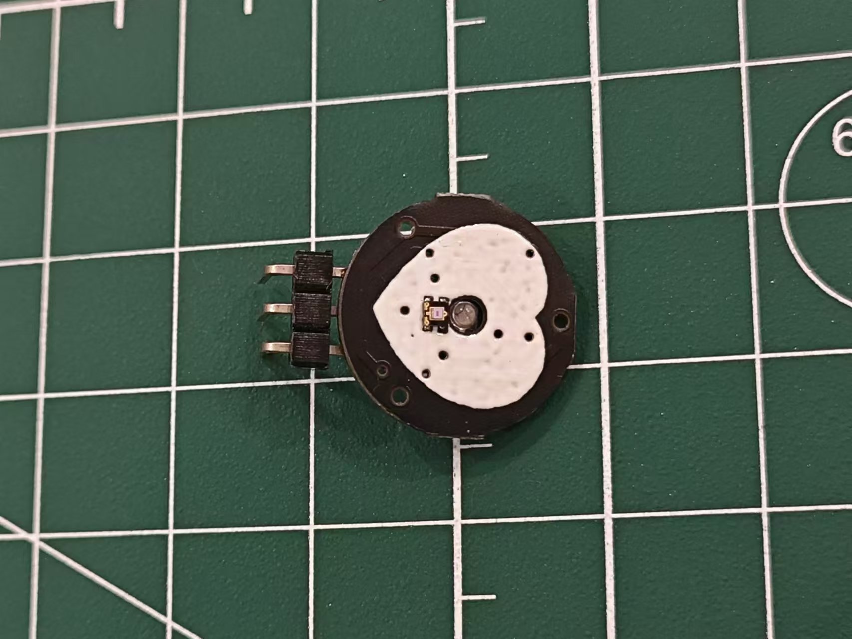
(2). The OLED and heart rate sensor pin headers should be as horizontal and vertical as possible to avoid affecting the alignment of the back cover and panel
(3). The minimum RC package is 0603, which can be done directly with a soldering iron
(4). The RGB LED pin spacing is small, so care should be taken to avoid solder bridging
(5). The others are all plug-in packages, which are not difficult.
6. Burning:
Use a burning tool such as the CH340 burner.
The connection is as follows:
PCB
burner
5V
5V
GND
GND
RX
TXD
TX
RXD
DTR
DTR
Use Arduino IDE to open the ino project file. First, download the necessary libraries:
PulseSensor Playground
Adafruit GFX Library
Adafruit SSD1306
. After selecting the serial port, click the upload button to complete the program burning.
If the DTR is not connected, you need to manually reset after clicking the upload button.
Note: The serial port method for burning programs is only applicable to 328p chips that have been burned with the boot program. If you buy it separately online, it is likely that it is a blank chip without the boot program. You need to use the Arduino UNO development board to burn the boot program to the chip first, and then you can use the above serial port method to burn other programs.
7. Assembly
(1) Paste the panel onto the upper shell
(2) First, fix the OLED screen onto the PCB using M2x4 screws*8 and M2x11 copper pillars*4
(3) Then install the heart rate sensor and fix the sensor with the 3D printed support pillar
(4) Place the whole thing on the bottom shell, install the upper shell, and fix the upper and lower shells with M3x8*4 screws to complete the process.
8. Use
(1) Insert the Type-C cable. It is recommended to use 5V power supply
(2) Slide the left power switch upwards to turn it on. The green light on the screen and heart rate sensor indicates normal operation. Gently press your finger on the heart rate sensor and wait a moment. The heart rate and pulse wave curve will be displayed on the screen.
(3) Press the lower touch switch to switch the display interface, which can be two lines with BPM, two lines without BPM, one line with BPM, or one line without BPM.
(4) The LED breathing light displays different colors according to different intervals. 0 is a solid red light, 1-59 flashes blue light, indicating a low heart rate, 60-89 flashes green light, indicating a normal heart rate, and above 90 flashes red light, indicating a high heart rate.
(5) Slide the lower switch to control the prompt sound. Left is off, right is on.
Attachment description:
Heartbeat_RELEASE.zip - Program code
Heart rate sensor support column V2-hole.STL - For components supporting the heart rate sensor, 3D printing orders are available.
Other
references include an international project: https://hackaday.io/project/167919-arduino-heart-beat-with-ecg-display-sound.
Improvements include: Hardware improvements such as reducing the PCB area and compacting all components to create a portable mini pulse wave and heart rate display; and software improvements such as optimizing the display interface by overlaying old curves with new ones for a more hospital-like look and adding function buttons for switching interfaces.
The PulseSensor heart rate sensor website is available at: https://pulsesensor.com/


 京公网安备 11010802033920号

 1200GGG500JA3EB


