The calculation basis for the UC3842 flyback experiment
is attached. This project will explain and correct any calculation errors (those that cannot be corrected are left uncorrected).
Design goals:
Vin = 220VAC
Vout = 24V
Iout = 10A
fs = 100KHz
η = 95%
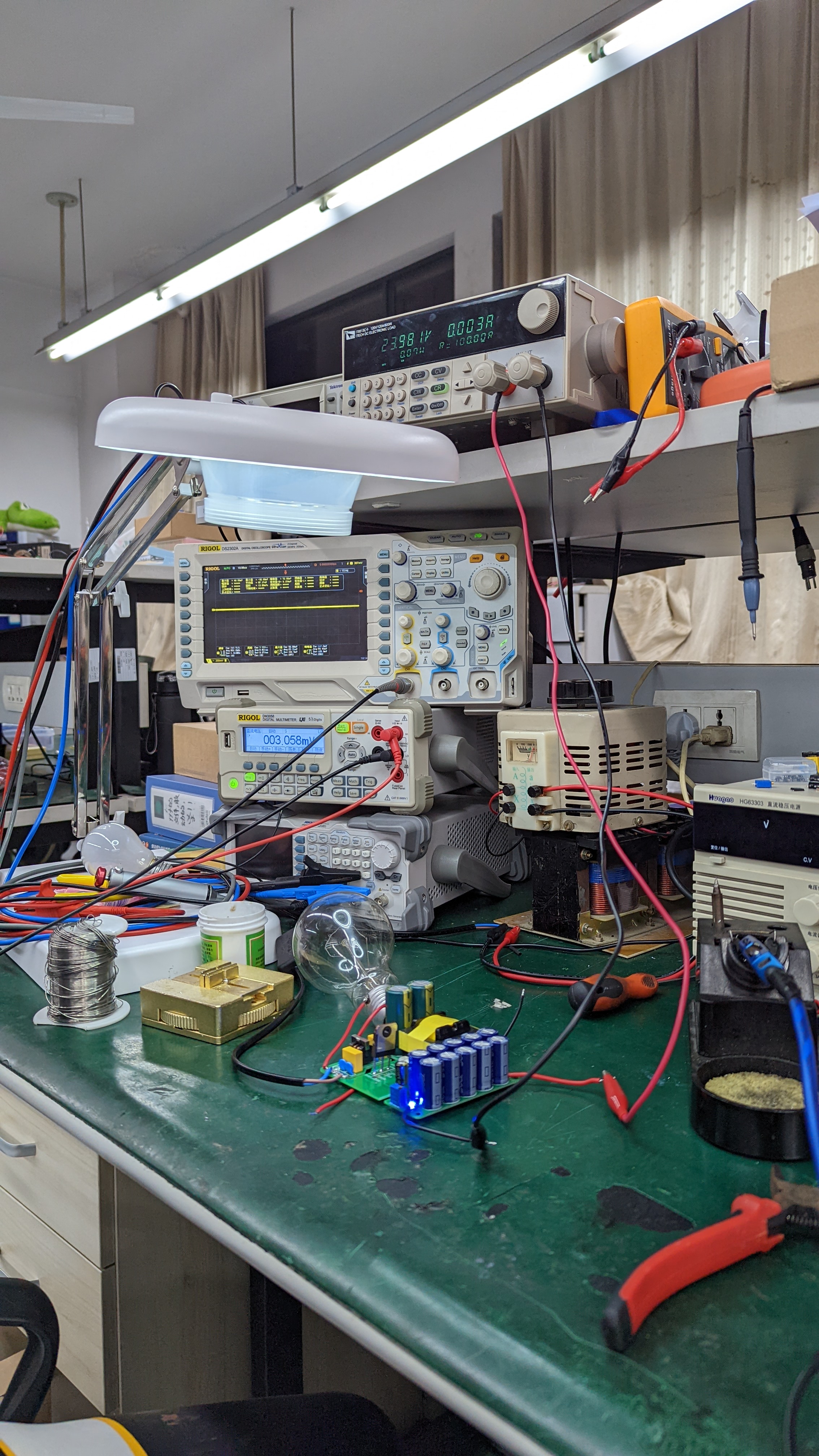
Test photos:
Power supply feasibility test:
Key point 1: The four pins need to be raised with copper pillars to avoid short circuits caused by metal impurities on the table. I couldn't find copper pillars, so I cleaned the table and used that instead.
Key point 2: The fuse can be replaced with an incandescent bulb. The brightness of the bulb can be used to determine the problem. Generally, the brighter the bulb, the more severe the short circuit. If it doesn't light up, it's normal. You can test with the bulb under light load. Under heavy load, you cannot use an incandescent bulb because it will be too bright and consume too much energy.
Key point 3: An isolation transformer must be used. Ideally, the oscilloscope should also be powered by an isolation transformer.

Feasible test results (note the electronic load above):
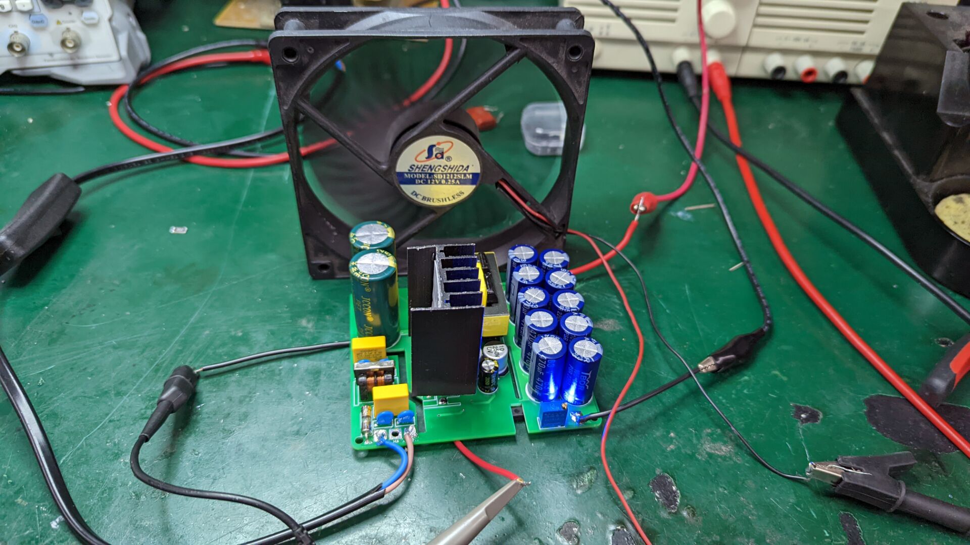
Power supply performance test:
Key point 1: The MOSFET needs a heatsink, and a small fan can be added to help dissipate heat.
Key point 2: After testing a point, solder the wire out. It's extremely dangerous to accidentally short-circuit the high-voltage side due to hand tremors, so for safety, test one point at a time and then test again.
Analysis of actual experimental results and circuit design shortcomings:
Efficiency did not reach 95%, and the RCD design had problems, resulting in many MOSFETs burning out. To test the peak voltage, high-voltage MOSFETs had to be used, which led to excessive MOSFET on-resistance, severe losses, and significantly reduced switching efficiency.
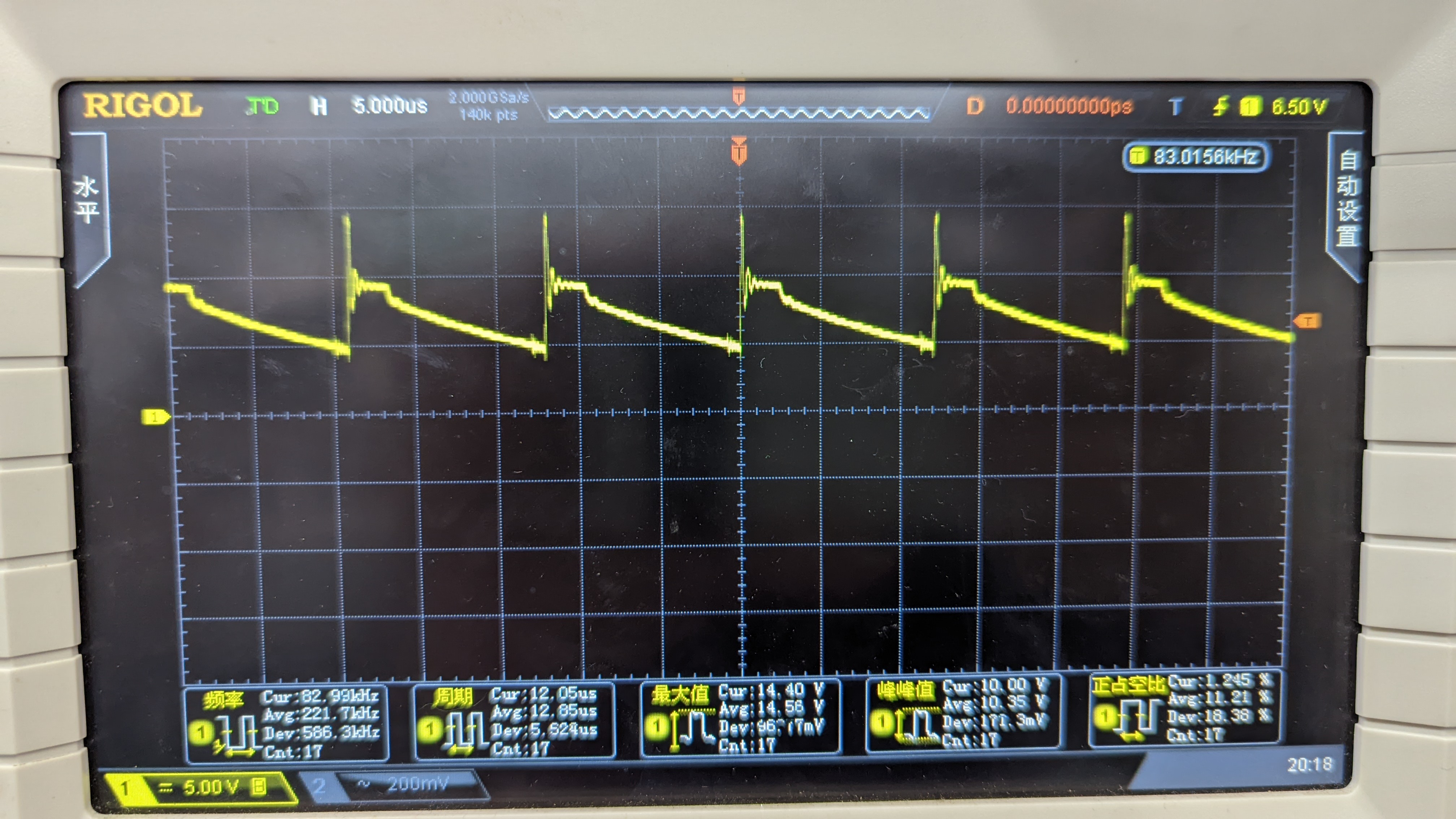
MOSFET drain waveform and RCD capacitor waveform:
Improved RCD design:
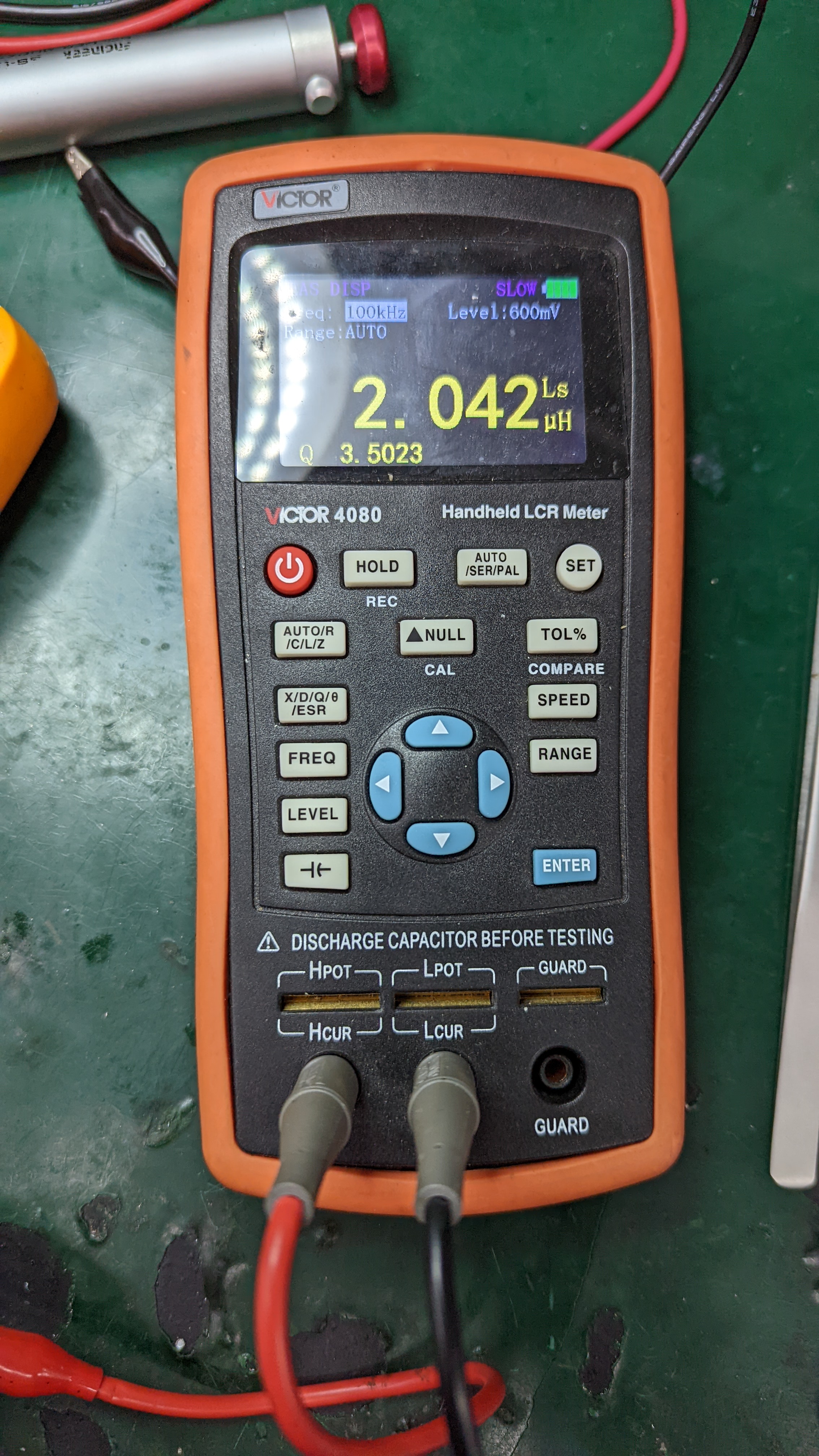
The peak voltage of the RCD is closely related to the leakage inductance, so we can test the leakage inductance.
Method for testing leakage inductance: Short-circuit all ports except the one under test, and directly test the inductance. Here, the inductance is 84uH, and the leakage inductance is 2uH.
RCD calculation (using MATLAB):
Vdsmax = 650 Vclamp = 0.9*Vdsmax - 374.767
Lk = 2.042*10^-6 Rc =(2*[Vclamp-19/5*(0.7+24)]*Vclamp)/ (Lk*Ip*Ip*fs)
Ip = 7.573 Cc = 2*Vclamp/(Rc*Vclamp*fs)
fs = 100*10^3 Pc = 0.5*fs*Lk*Ip*Ip*(1+(100/(Vclamp-100)))
Dmax = 0.4625
Results obtained:

Capacitor and resistor selection: C=4.7nF, R=4KR.
MOSFET drain waveform (half-load and full-load) and RCD capacitor waveform:

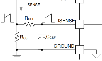
The output power only reached 180W. After reaching 180W, the output voltage dropped to maintain the output current. According to the official chip datasheet, a filter capacitor can be connected in parallel with the peak current sampling resistor to prevent voltage spikes. My peak current sampling resistor design also has some issues.
The actual output ripple is not large, but the output spike is particularly large. This may be because even though the output capacitor is large, no small capacitors to filter high frequencies were added.
PCB Notes:
Capacitor C11 is a compensation capacitor. I did not solder it during actual testing. If it were soldered, the UC3842 would not be able to adjust properly. Of course, this may change after detailed calculations.
Design Insights:
The UC3842 is indeed one of the most widely used power supply chips. Its structure is simple and the design is not complex, making it very versatile in low-power applications, but its performance in high-power applications is questionable.
The RCD design is still not very reasonable. I tried many different data points, but I still cannot completely eliminate ringing. I hope someone knowledgeable can offer some suggestions.
I will gradually add more details later, writing as much as I feel like.


 京公网安备 11010802033920号

 CCL225DE3-W


