Project Description:
This project is a 50W switching power supply. Input voltage range: AC110V-440V; output voltage: DC 5-24V; power: 50W; peak power: 70W; maximum output current: 10A; efficiency: 90%.
For those who have questions, please join QQ group 458720579.
Open source license
: GPL 3.0.
Project functions:
Can be connected to different AC voltage environments (380V or 220V
). Power supply power is approximately 50W (5V output 10A, 24V output 2A).
Automatically identifies the input voltage level ;
output is DC voltage;
DC output voltage can be manually adjusted (5-24V);
automatic voltage regulation function is required for the output DC voltage.
The power supply has overcurrent, overvoltage, and short-circuit protection .
Project Attributes:
This project is being publicly disclosed for the first time and is my original work. This project has not won any awards in other competitions.
Project Schedule:
March 26 - Project Started Design Scheme;
April 1 - Schematic Drawing;
April 4 - PCB
Layout; April 11 - Board Fabrication;
April 20 - Successful Debugging, Performance Optimization;
April 22 - Debugging Completed.
Design Principles :
1. Project Analysis:
The project is a 220V/380V dual-input power supply. When supporting 380V input, attention needs to be paid to component voltage withstand and creepage factors. For flyback topologies, with high input and constant output voltage, only the duty cycle is reduced. However, the input voltage cannot be too low. Two factors determine our minimum input voltage: first, the duty cycle cannot exceed 0.5; second, the peak current of the MOSFET.
With 220V/380V dual input and a fixed 24V output, a standard flyback topology can handle it. However, the requirement is 5-24V adjustable, so the auxiliary power supply coil voltage of the flyback will also change with the output voltage, causing low-voltage operation to fail.
This project adopts a flyback + synchronous BUCK topology.
The main focus here is on the high-voltage input solution
. With a 380V input, the effective AC voltage will fluctuate to 420V, resulting in a rectified DC voltage of 420 x 1.414 = 593V.
Ordinary electrolytic capacitors have a withstand voltage of around 450V, requiring two capacitors in series to accommodate the high-voltage input. A balancing resistor is also needed to address the voltage balance issue between the two capacitors.
Similarly, under low voltage, the MOS current experiences the most significant stress, calculated to be 3A
. Furthermore, component stress calculations are crucial. Components whose stress varies with input voltage include the switching MOS transistor and the output rectifier diode.
The calculation formula is as follows:

Select a 400V Schottky diode for the diode and a 900V 15A MOS transistor.
2. Transformer Design
. The next important step is transformer calculation. The most difficult part of the entire project was the transformer design. A good transformer ensures stable power supply operation. For transformer design, it's recommended to learn through the MPS flyback transformer design page and perform the calculations yourself. I've summarized the flyback transformer calculation into 6 steps
: 1. Determine the turns ratio (Vinmin minimum input voltage, Dmax maximum duty cycle) ;
2. Calculate the peak current
; 3. Calculate the primary inductance (Ton switching cycle high-level time);
4. Calculate the primary turns (B is 0.2-0.25, Ae is the core cross-sectional area, here it's 118 of 2625)
; 5. Calculate the secondary turns;
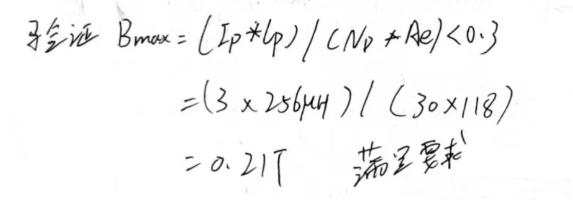
6. Verify correctness (Bmax is less than 0.3).

The transformer datasheet diagram
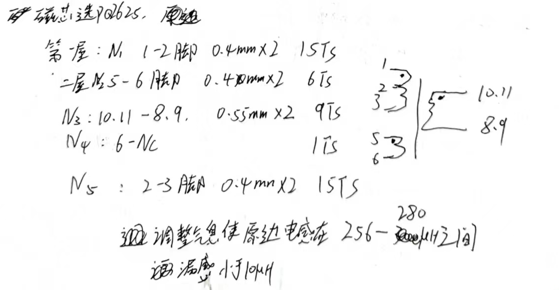
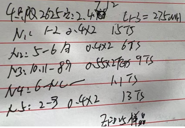
above shows the data provided by the prototyping manufacturer; pin 6 is connected to a single layer of copper foil. Note that in actual n5 designs, reducing leakage inductance can increase to 15 turns, but the minimum input voltage will change.
Currently, the actual prototyping transformer is working normally and needs further refinement. A primary inductance of 300uH and a leakage inductance of 3-5uH are recommended.
Note that pins 2, 7, and 12 must be cut off.
3. Main Power Supply Circuit Analysis

: The diagram above shows a flyback circuit. The focus is on the power-on process and short-circuit protection.
First, the input 380V becomes 540V after rectification by the bridge. Two capacitors are connected in series to divide the voltage, which is then sent to the PWM chip through the starting sampling resistor. The PWM chip generates a primary waveform, resulting in a 16V induced voltage in the auxiliary winding. This voltage is then regulated to 14V by the voltage regulator circuit and sent to the PWM chip. The voltage at no-load C13 is 16V, and at full load it is 18V.
When the output is short-circuited, the auxiliary power supply is pulled low, and the chip enters hiccup mode. At this time, the power supply is provided by the starting resistor.
Overvoltage protection occurs when the output voltage exceeds 30V. D7 conducts, pulling COMP low and entering protection mode.
Note that the MOSFET used must be the one marked on my schematic, requiring a voltage rating of 900V or higher. In actual full-load testing, the highest DS voltage is 800V. Also, note that all components in the preceding stage must have a voltage rating of 700V or higher. Please double-check these specifications.
4. Auxiliary Power Supply Circuit Analysis:

The auxiliary output power supply is an EG1163S synchronous step-down converter. I have used this circuit multiple times, and the solution is relatively stable. The main circuit principle will not be elaborated here; instead, the debugging approach will be explained.
During actual debugging, it was found that the actual circuit according to the official schematic, with a 27V input and 5V output, had a no-load current of 0.4A. A large no-load current indicates that both the upper and lower transistors are conducting simultaneously. Observing the waveform of the upper transistor with an oscilloscope, the waveform was a large and small wave, not a normal square wave. When the output voltage was adjusted to above 6V, the no-load current was 0.04A, returning to normal.
The official recommendation for the loop compensation capacitor is 10nF; increasing it to 20nF resolved the issue, and the waveform returned to normal upon power-up. The key to debugging the circuit is oscilloscope observation and theoretical analysis. Actual testing showed that the overcurrent protection was 14A; exceeding 14A resulted in a
maximum output voltage of 12.5A at 0.5V and 2.5A at 24V. Please note that the power limit should not be exceeded. Also, the 5V 10A cannot be used for extended periods; a cooling fan is required for prolonged operation. A 24V output of 3A may cause the 24V to drop to 23V. This power supply is designed for a power consumption of 50W or less. Do not use it in extreme environments; you are responsible for any consequences.
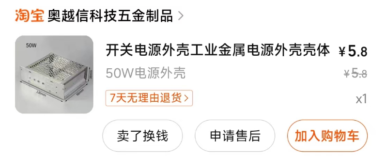
5. Case Design and Component Procurement:
The case uses a generic mold, and the heat dissipation method is natural cooling. Thermal putty should be used on the MOSFETs underneath.

The GR8836CG can be replaced pin-to-pin and is available at LCSC Mall, but the D8 Zener diode in the schematic needs to be replaced with a 17V Zener diode (GR8836CG's turn-on voltage is 15V).

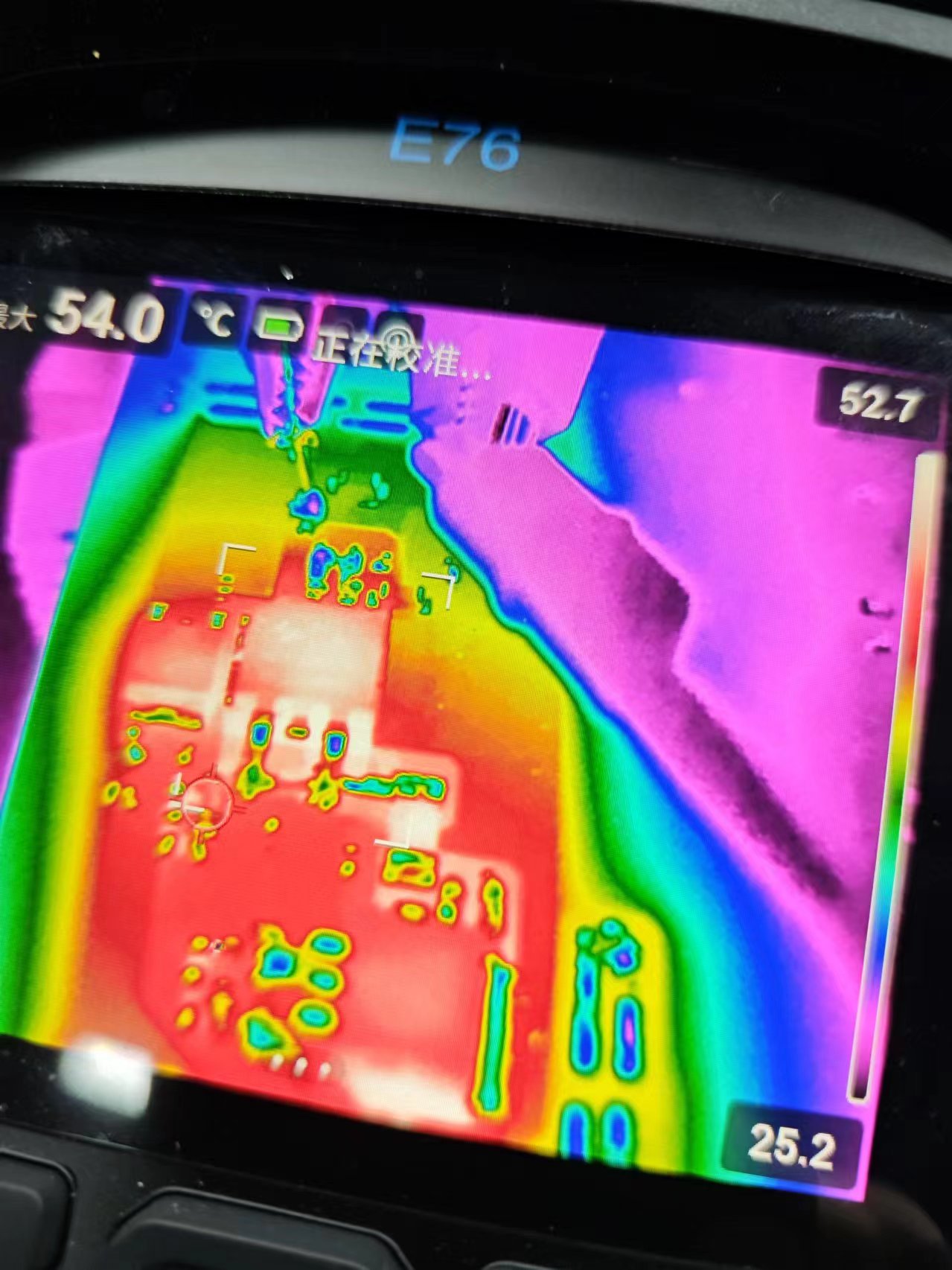
6. Temperature Testing:
Without the case installed, the synchronous buck MOSFET temperature is 54 degrees Celsius after 30 minutes of full load at 5V 10A.
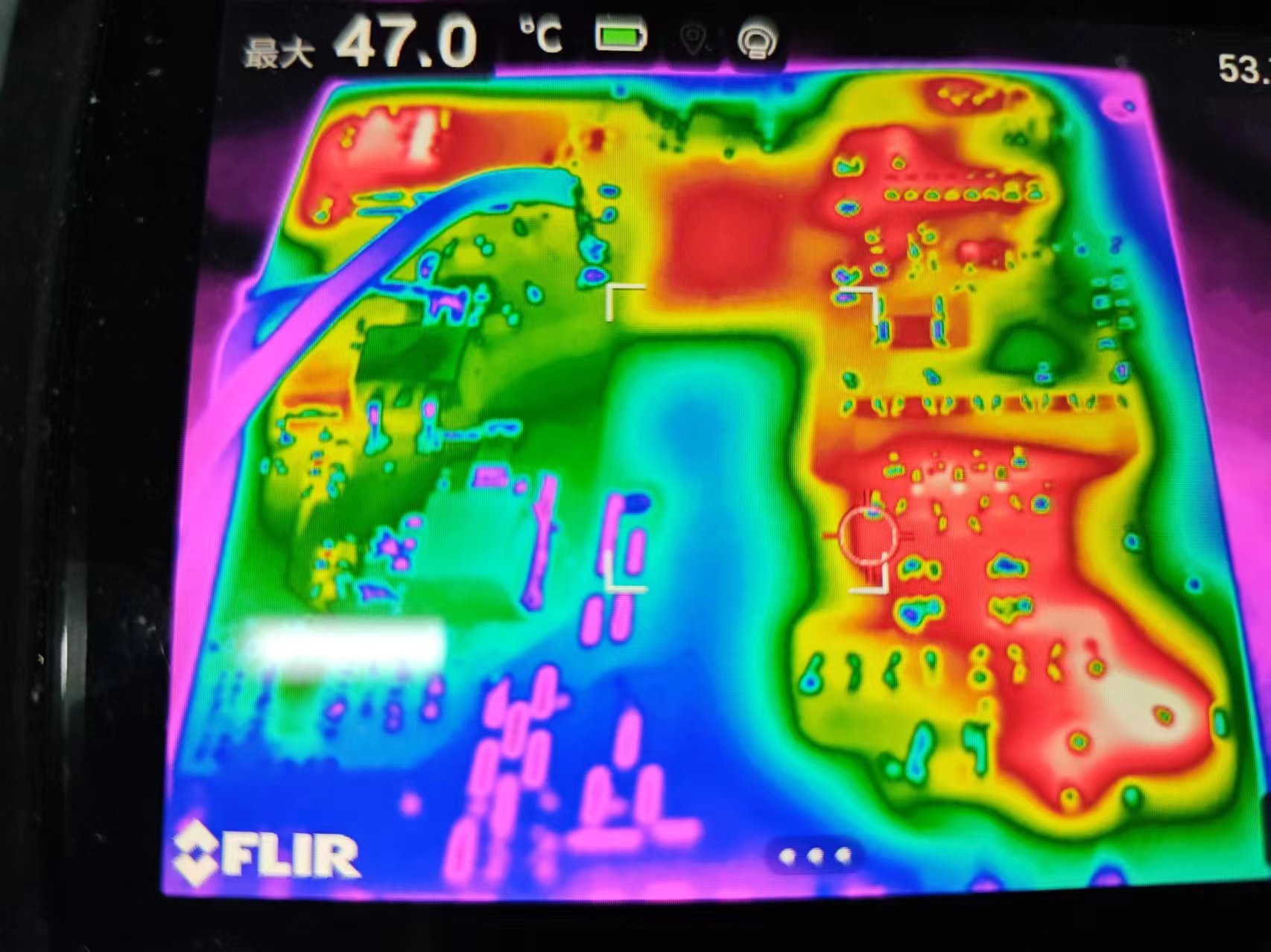
Without the case installed, the flyback MOSFET temperature is 70 degrees Celsius after 30 minutes of full load at 27V 2.6A 70W. The highest temperature is found on the back RC absorber at 53 degrees Celsius.
The temperature improves after installing the case; the synchronous rectifier MOSFET temperature is 40 degrees Celsius, and the flyback MOSFET temperature is 55 degrees Celsius. However, it cannot be used in a confined environment and requires ventilation (at 5V 10A output). Considerations for
Physical Display Design

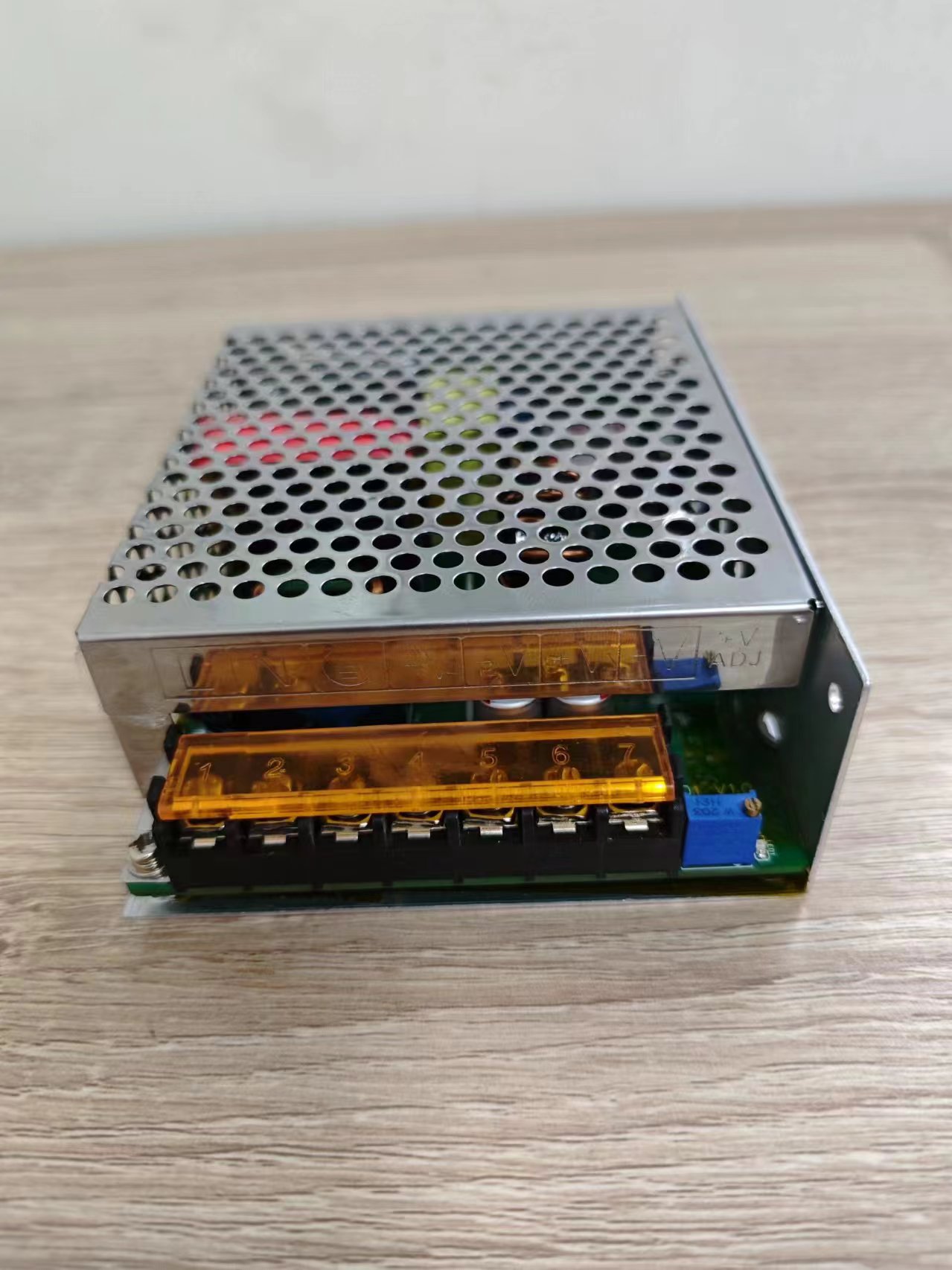
This project involves high-voltage electricity; please exercise extreme caution when using it. You are solely responsible for any consequences. Limit the current during debugging.
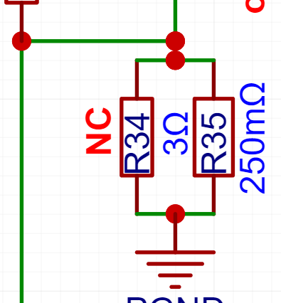
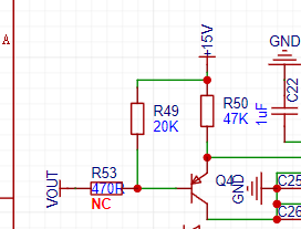
Also, there are two non-NC resistors in the project; do not solder them. R34 and R53.
Other details
: https://www.bilibili.com/video/BV1kp421D7f5


 京公网安备 11010802033920号

 10121750-0120038LF


