LCSC Development Board Electronic Design Training Camp Registration Portal
https://oshwhub.com/activities/LSP-dian-zi-she-ji
Project and Requirements
Design and Implementation of Intelligent Curtain Device Based on Liangshan School
1. Background
With the development of science and technology and the improvement of people's living standards, intelligent home systems are increasingly appearing in people's lives, bringing people a fast and comfortable experience. For household necessities, curtains occupy an important position. Since manual curtains need to be opened and closed manually, electric curtains cannot be automatically controlled according to light and require a specific remote control, which has certain limitations. Therefore, an intelligent curtain control system based on Liangshan School microcontroller was designed.
2. Design Requirements and Indicators
Technical Requirements
(1) Raindrop sensor module: used to detect raindrops;
(2) Light intensity sensor module: used to detect light intensity;
(3) Infrared receiving module: used for remote control;
(4) Stepper motor module: used for window curtain drive.
Technical Specifications
(1) Automatic mode can be set via infrared remote control and voice;
(2) In automatic mode, the curtains will automatically open when the light intensity is high and automatically close when the light intensity is low;
(3) In automatic mode, the curtains will automatically open when a large number of raindrops are detected, which has a higher priority than light detection;
(4) The curtains can be opened and closed at any time via infrared remote control or voice command, and the automatic mode can be turned off;
(5) After receiving the data, the main control chip will drive the motor to run, realizing the intelligent curtain window system.
I. Raindrop and Light Detection
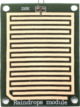
1. Raindrop Detection Principle
The common working principle of raindrop sensors is to determine whether it is raining by detecting the conductivity of water droplets. It uses the change in conductivity between two electrodes to measure the presence of water droplets. There is an air gap between the two electrodes, which is normally an open circuit. When a water droplet comes into contact with the electrode, the conductivity of the water droplet will cause current to flow through the water droplet to form a current loop, thereby changing the resistance value between the electrodes. By measuring the change in resistance value, it can be determined whether there are water droplets.
2. Raindrop Sensor Interface Design
We know that the raindrop sensor detects changes in resistance based on raindrops. How then do we use it to detect raindrops?
We connect the raindrop sensor to a power source. When the resistance of the raindrop sensor changes, its voltage also changes. We can think of the raindrop sensor as a switch. When there are no raindrops, the raindrop sensor is open-circuited because there is no short circuit.
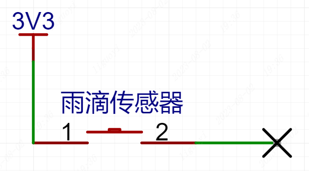
When there are raindrops, the raindrop sensor short-circuits because the raindrops are conductive, equivalent to a button being pressed.
Therefore, we can determine the presence of raindrops by measuring the voltage change of the raindrop sensor.
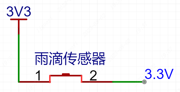
The expansion board's raindrop sensor interface is as follows:
We need to connect one terminal of the raindrop sensor to positive and the other to negative to create a loop for measuring voltage changes. However, too many raindrops can cause a complete short circuit between the two terminals. To prevent this, a resistor R1 is added as a load to prevent the 3.3V from being directly connected to GND, thus preventing a power short circuit.

3. Light Detection Principle
The light detection function of the expansion board is based on a photoresistor. A photoresistor is a special type of resistor whose resistance decreases rapidly with increasing light intensity. In the absence of light, it exhibits almost high resistance, resulting in very high resistance in the dark.
The most common light detection modules on the market use photoresistors as their primary identification device. Its schematic diagram is shown on the right. U2.1 in the schematic is a voltage comparator. When the voltage at pin 2 of the comparator is greater than the voltage at pin 3, pin 1 outputs a low level; when the voltage at pin 2 is less than the voltage at pin 3, pin 1 outputs a high level. R3 is the photoresistor. When the surrounding environment is bright, its resistance decreases, and the voltage at AO also decreases; when the surrounding environment is dark, its resistance increases, and the voltage at AO also increases. Therefore, by adjusting the resistance of the sliding resistor R4, the sensitivity of the DO output can be adjusted.
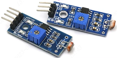
4. Light Sensor Interface Design
We simplify the module schematic by using a voltage divider resistor and a photoresistor. Our expansion board directly detects the voltage change of the photoresistor, as shown in the AO section of the module schematic.

II. Stepper Motor Drive
1. Introduction to Stepper Motors
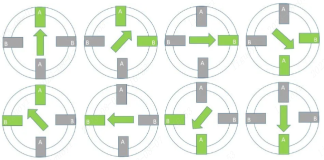
A stepper motor is an open-loop controlled motor that converts electrical pulse signals into angular or linear displacement; it is also known as a pulse motor. The most important components of a stepper motor are the rotor and the stator.
The stator is controlled by current to direct the magnetic field; when energized, it generates magnetic force.
The rotor, surrounded by the stator, rotates due to changes in the stator's magnetic field (the rotating pointer in the diagram below).
By energizing the stator, a magnetic force is generated, attracting the rotor, causing it to rotate a small increment. Continuous energization of the stator allows the rotor to rotate.
Under non-overload conditions, the motor's speed and stopping position depend only on the frequency and number of pulse signals. When the stepper driver receives a pulse signal, it can drive the stepper motor to rotate a fixed angle in a set direction. Therefore:
the angular displacement can be controlled by controlling the number of pulses, achieving accurate positioning;
the speed and acceleration of the motor can be controlled by controlling the pulse frequency, achieving speed regulation; and the forward and
reverse rotation of the motor can be controlled by controlling the energizing sequence of the windings.
2. For the stepper motor rotation,
we purchased a two-phase four-wire stepper motor. "Two-phase" means there are two coils, and "four-wire" means each coil has two wires. A+ and A- form one phase, and B+ and B- form another.
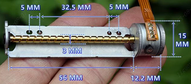
Purchase link: Original imported Y15-56 two-phase four-wire miniature stepper motor with slider
. To make it rotate, the coils need continuous power. There are four-step and eight-step rotation methods.
The rotation sequence for the four-step method is: [A+]->[B+]->[A-]->[B-].

The rotation sequence for the eight-step method is: [A+]->[A+B+]->[B+]->[B+A-]->[A-]->[AB-]->[B-]->[B-]->[B-A+].
Using a magnetic motor, the higher the current, the stronger the magnetic force. Although it's possible to directly control the stepper motor using the development board's GPIO, there's a risk of damaging the development board pins. Therefore, we need to consider a suitable stepper motor driver.
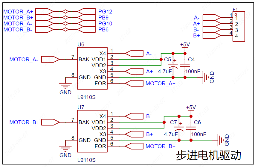
3. Stepper Motor Hardware Driver Design
Case: This case uses the L9110S as the stepper motor driver, and its datasheet includes an application circuit. We can design according to the datasheet instructions.
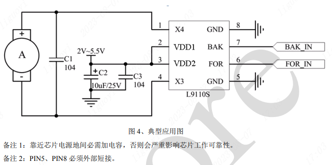
BAK controls the level output of pin X4; FOR controls the level output of pin X3. Motor A in the diagram only needs to be connected to one phase of the stepper motor. Following this approach, two L9110S controllers are needed to drive a two-phase four-wire stepper motor.
III. Infrared Receiver Driver
1. Introduction to Infrared Protocol
In the electromagnetic spectrum, wavelengths from 760nm to 400um are called infrared radiation, which is invisible light. We are all familiar with examples of infrared communication; almost all commonly used home appliances can be controlled via infrared remote control, such as televisions, air conditioners, and projectors. This technology is widely used, and the corresponding components are very inexpensive, making infrared remote control an ideal method for controlling our everyday devices.
2. The Communication Principle of Infrared
Light Infrared light is emitted in the form of pulses at a specific frequency. After receiving the signal, the receiving end decodes it according to the agreed protocol to complete the data transmission. In consumer electronics, the pulse frequency generally uses the 30kHz to 60kHz band, while the NEC protocol frequency is 38kHz. This emission at a specific frequency can be understood as turning on a light. Don't be intimidated by the complex terminology; it simply means controlling the blinking frequency (on and off) of a light, similar to implementing a blinking light when you first learn about microcontrollers, only the type of light is different—it's still a light. The principle of the receiver: The receiver chip is sensitive to infrared light and can output high and low levels depending on the presence or absence of light. If the flashing frequency of the transmitter is regular, the high and low levels output by the receiver will also correspond regularly. Once the transmitter and receiver agree on this, data transmission can proceed.
Infrared transmission protocols are arguably the lowest-cost and most convenient of all wireless transmission protocols, but they also have drawbacks, such as insufficient range and speed. Of course, each transmission protocol has different application environments and positioning, so it's impossible to compare their merits directly. The appropriate communication method should be chosen based on the specific scenario.
3. Introduction to the NEC Protocol:
The NEC protocol is one of many infrared protocols (these protocols differ only in their data frame format definitions; the data transmission principle is the same). Most of the remote controls we buy, mini remote controls from Taobao, televisions, and projectors use the NEC protocol. Devices like Gree and Midea air conditioners use other protocol formats, not NEC. However, once you learn one protocol parsing method and understand the infrared transmission principle, you can decode other remote control protocols.
A complete NEC protocol transmission includes: a preamble, an 8-bit address code, an 8-bit address inverse code, an 8-bit command code, and an 8-bit command inverse code. Here, we mainly explain how to receive NEC protocol content sent by the infrared transmitter.

The preamble consists of a 9ms low level followed by a 4.5ms high level.

The 4 bytes of data are: address code + address inverse code + command code + command inverse code. The inverse code is used to verify whether the data transmission is correct and whether there is any packet loss.
Important: When transmitting data bits, the NEC protocol distinguishes between 0 and 1 based on the duration of the received high and low levels. This is crucial for decoding.
Data transmission 0: 0.56ms low level + 0.56ms high level.
Data transmission 1: 0.56ms low level + 1.68ms high level.
Therefore, the complete time representation of receiving a data bit is as follows:
Received data bit 0: 0.56ms low level + 0.56ms high level;
Received data bit 1: 0.56ms low level + 1.68ms high level.
There is also a repetition code, which consists of a 9ms low level and a 2.5ms high level. When an infrared signal is continuously transmitted, it can be transmitted quickly by sending the repetition code.
4. Infrared Receiver Hardware Interface Design
The principle of the output level of the infrared receiver module: The infrared receiver outputs a low level when it senses infrared light, and a high level when it does not sense infrared light. Therefore, we only need to detect whether the OUT terminal outputs a low level to know whether infrared data has been received.
Here, we choose to connect PF7, which has no special requirements and can use ordinary GPIO.

IV. Voice Recognition Driver
1. Voice Module Introduction
The HLK-V20 is a high-performance, purely offline voice recognition module launched by Hailink Electronics for a large number of purely offline control scenarios and products. It can be widely and quickly applied to smart homes, various smart small appliances, 86-type set-top boxes, toys, lighting fixtures, industrial, medical, IoT, automotive, security and lighting products that require voice control. The HLK-V20 supports offline recognition of 150 local commands, and can freely customize wake-up words, command words, and response broadcast words. It has rich peripheral interfaces. Offline voice recognition means that it can only recognize fixed command words and does not require a network connection.
Purchase Link: AI Smart Voice Module V20 Hailink Offline Voice Switch Control Voice Recognition Control Development Board
The configuration of command words, broadcast words, etc. of the Hailink offline voice switch control voice recognition control development board module can be configured through the online configuration platform. Due to its length, a separate document has been created. See the link below for specific voice product configuration examples.
Hailink Voice Recognition Module Voice Firmware Creation and Download
This example comes from the HLK-V20 voice recognition module in Chapter 4.13 of the module porting manual.
Following the configuration process of the reference case, the voice module pin settings in this case also select B2P3 as serial port 1.

Wake-up word settings:

Command words and control:
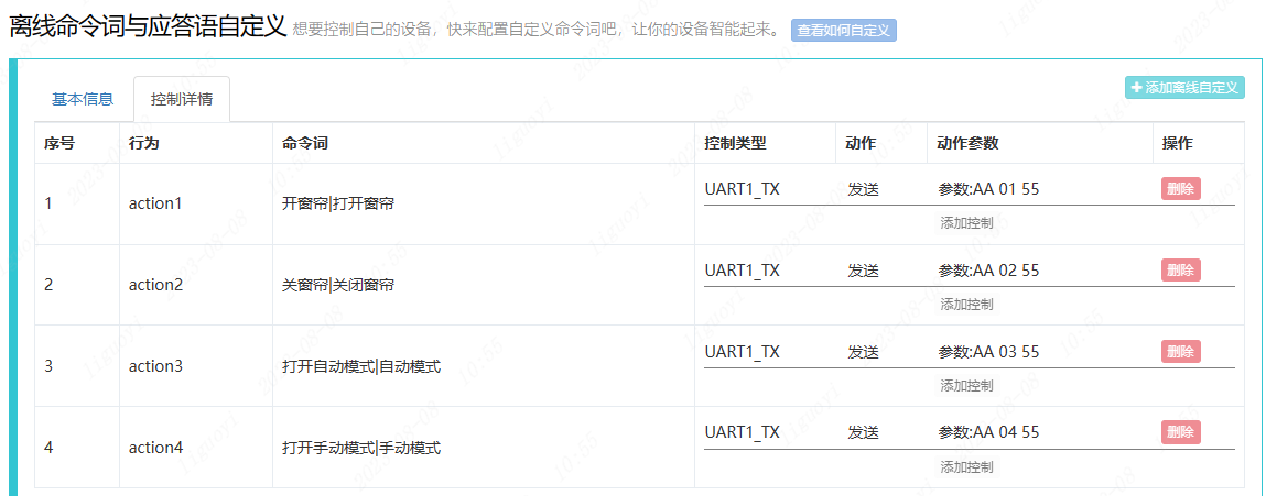
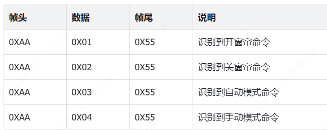
The control parameters are set as follows. When the serial port receives 0XAA 0X01 0X55, it indicates that the voice module has triggered the command to open the curtains. The same applies to other commands. To facilitate receiving and parsing multiple commands, a frame header and frame footer format is used. When the serial port receives 0X55, it indicates that the voice recognition module has triggered a command. Analyzing the previously received data reveals which command was recognized.
`if( RX_BUFF[DATA_LEN] == 0X55 )//Received frame footer
{
if( RX_BUFF[DATA_LEN-2] == 0XAA)//Received frame header, confirming correct data format
{
V20_data = cRX_BUFF[DATA_LEN-1];//Received data
}
}`
For example: If the voice recognition module sends the command: 0XAA 0X03 0X55, it indicates that the command to open automatic mode has been triggered.
Other settings:

2. Speech Recognition Module Hardware Design
This speech recognition module allows us to freely design command words and can be configured through an online configuration platform. After configuration, a speech recognition firmware will be generated. We need to download the firmware to the module via pins B6 and B7. Therefore, pins B6 and B7 are brought out via headers below for easy downloading. It is also important to note that the module must be powered off before downloading the firmware. Power should only be applied after the download tool recognizes the module for normal downloading. This power-on/off operation is controlled by switch SW1 in the schematic diagram.

For the software design of the entire case, please refer to the document: https://lceda001.feishu.cn/docx/X2z8dgeRSoguQwxBEsjc3p64n5b?from=from_copylink


 京公网安备 11010802033920号

 1812F2000123FFT


