2024/11/09: I replaced the multimeter, and the standby power consumption was a whopping 200 microamps. I promptly designed a version with physical shutdown, which has already been prototyped and tested. If the seller can fix the bug of high power consumption during soft shutdown, the original one can also be reused .

2024/10/14: The chip seller said the microphone only works during calls.
Video link:
Bilibili video -- Function demonstration and introduction
Project Introduction
Most helmet headsets on the market require an external host. I personally think this not only ruins the aesthetics but also increases wind noise. Therefore, I created this hidden helmet Bluetooth headset
project. Functionality
This project is based on the Jerry AC6955F with pre-programmed code, saving the coding process and improving efficiency.
The entire project consists of two PCB boards: a main board (required) and a control board (customizable). The full-function control board includes a power button, three function buttons, a charging port, and three indicator lights (status, charging, charging complete). It can be reduced to a minimum of only one charging port and one power button.
It has basic Bluetooth headset functions, supporting call/music
playback.
The motherboard PCB diameter is 2.3cm, a small board of 7mm x 40mm. The
main controller is a Jerry AC6955F
with a programmable microphone (analog silicon/electret condenser) .
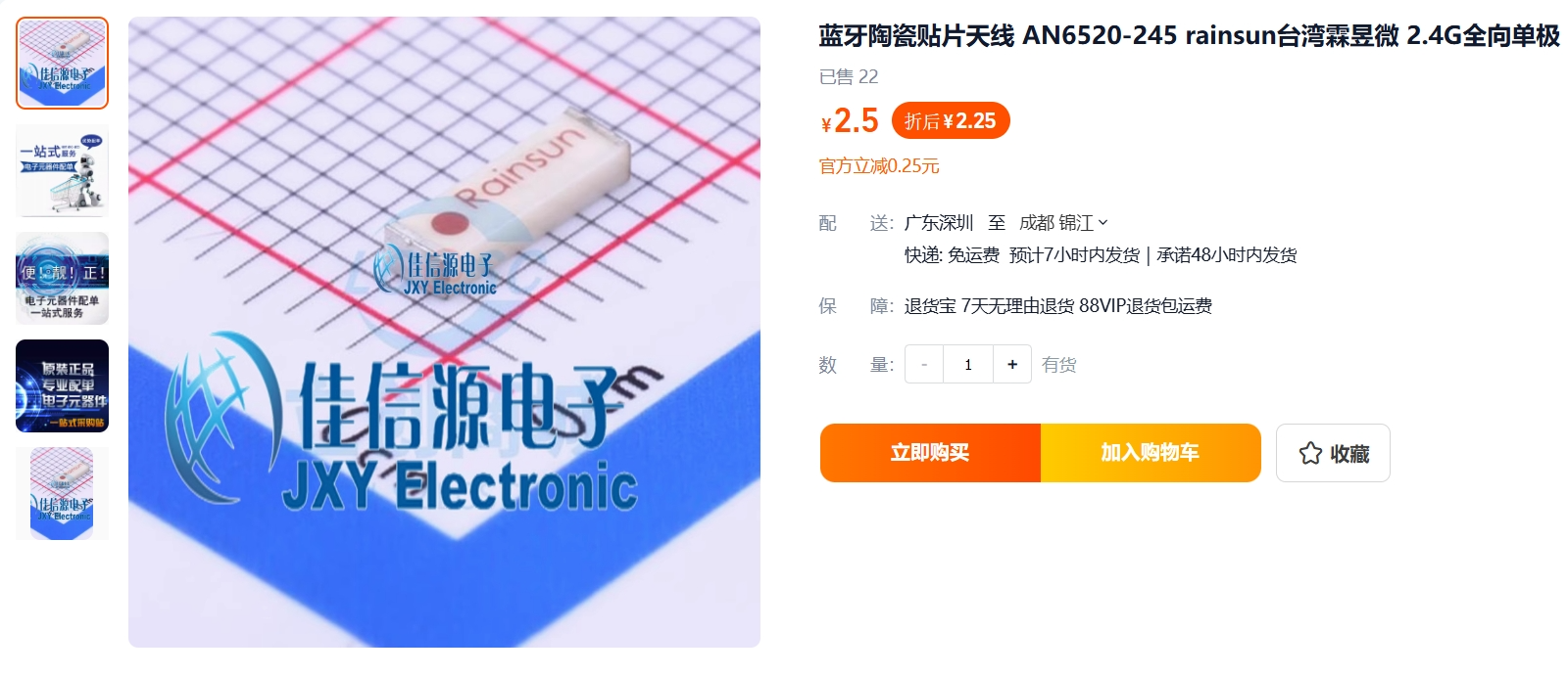
The ceramic antenna can be a 1206 or 2x5.1mm package. A parallel capacitor is reserved for adjustment.
Continuous music playback lasts approximately 8 hours; standby time has not yet been tested (theoretically 30 days).
Hardware specifications
: Main control circuit:
Uses AC6955F, selected with a programmable chip. The main circuit is drawn based on the schematic provided by the seller and Jerry's related materials. The PB11 resistor adjusts the brightness of the status indicator light; a smaller resistance value results in a brighter light.

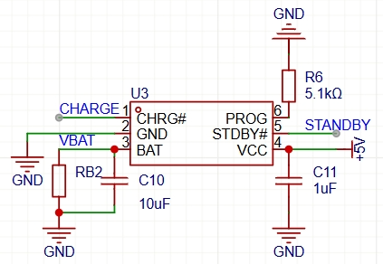
Lithium battery charging circuit:
Uses TP4057 (I had this on hand, but it can be replaced with other chips), with all pins brought out. A 5.1K programmable resistor is selected, with a charging current of approximately 200mA. This can be modified; a larger resistance value results in a lower charging current (because...). (For headphones, it's not recommended to set the value too high)
Speaker circuit:
Draw according to Jerry's recommended circuit. The position of the direct-blocking capacitor in the diagram can be either a capacitor or an inductor. I used the 120nH inductor from the manual. The manual recommends 220nH for the common ground, but I was too lazy to buy another one, so I used 120nH. I also reserved space for a filter capacitor. Personally, I just need it to make a sound. The specific selection for this part depends on your requirements.

Small board circuit:
This is even simpler. One TYPE-C female connector, four buttons, and three LEDs are connected. The TVS diode D1 is optional. R18 and R19 adjust the brightness of the charging indicator light. I chose 5.1K, the same as the status indicator light. The buttons use ADC input; different voltage ranges correspond to different button functions. Don't follow the seller's schematic diagram exactly; it's different.

Note that
the speaker pads, from left to right, are: left ear negative, left ear positive, right ear negative, and right ear positive.

The button board pads correspond as follows:
S -> Status indicator;
K -> Button;
C -> Charging indicator;
D -> Charging complete indicator;
B+ -> Battery positive;
B- -> Battery negative ;
G -> Board GND
5V. -> The 5V power supply
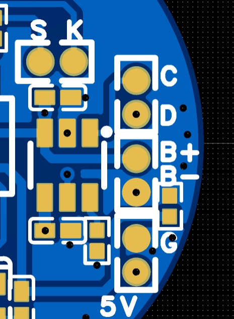
provided by this company defaults to hard boot, so I recommend soldering the battery negative terminal with a large copper area first. This way, when soldering the positive terminal, the soldering iron can easily reach it.
After booting, you can download the accompanying APP and send AT commands to achieve soft shutdown (be sure to test the function is normal before setting it), or rename it (after renaming, you can no longer use the APP to modify parameters).
Component purchase:
I bought the main controller from this company. For other companies, you need to ask for
the purchase link

. The purchase of speakers can be based on your own needs. I used 40mm thick, 6mm thick disassembled speakers (this thickness can only be less, not more). If you have money, you can choose better and thinner ones. Here are a few recommendations: Disassemble your own headphones, 6mm thick, 4 ohms, 3W; 6mm thick, 32 ohms, 4mm thick.
You need to buy two types of wire, 4-core and 6-core enameled wire, one meter is enough. Purchase link: enameled

wire. Use 402030 batteries, any store on Taobao will do. If you have the ability, you can buy this type of round battery, I can help you modify the shell model. After purchasing the battery, peel off the tape and replace it with the 4-core enameled wire. When soldering, pay attention to the length allowance, as there are two more wires to connect to the speaker. For the

ceramic antenna, you can choose RainSUN's model, CrossAir's CA-03, or the more common 1206 package. I haven't had the opportunity to test the impact of different antenna maximum power consumption on battery life yet; those who do can try it.


Assembly Notes:
The casing and motherboard have an interference fit; simply press firmly into place during installation. The base has clips that correspond to the grooves on the casing, allowing for installation and fixation without glue or screws. Align the speaker wire end with the notch side; otherwise, excessive solder will prevent the casing from fitting.
The headphone casing is universal; note the quantities at the end of the document.


 京公网安备 11010802033920号

 BS616LV1015AI-55


