 Features: The layout is inspired by smart car motherboards. The input interface features a dedicated TO-252 packaged N-channel MOSFET for reverse connection protection and switching, resolving arcing issues upon power-up. R1 and C1 can be left unsoldered. For the 3538 circuit with higher power, a 1770 package inductor is used, while the 3526 uses a 1265 package to minimize inductor heat generation.
 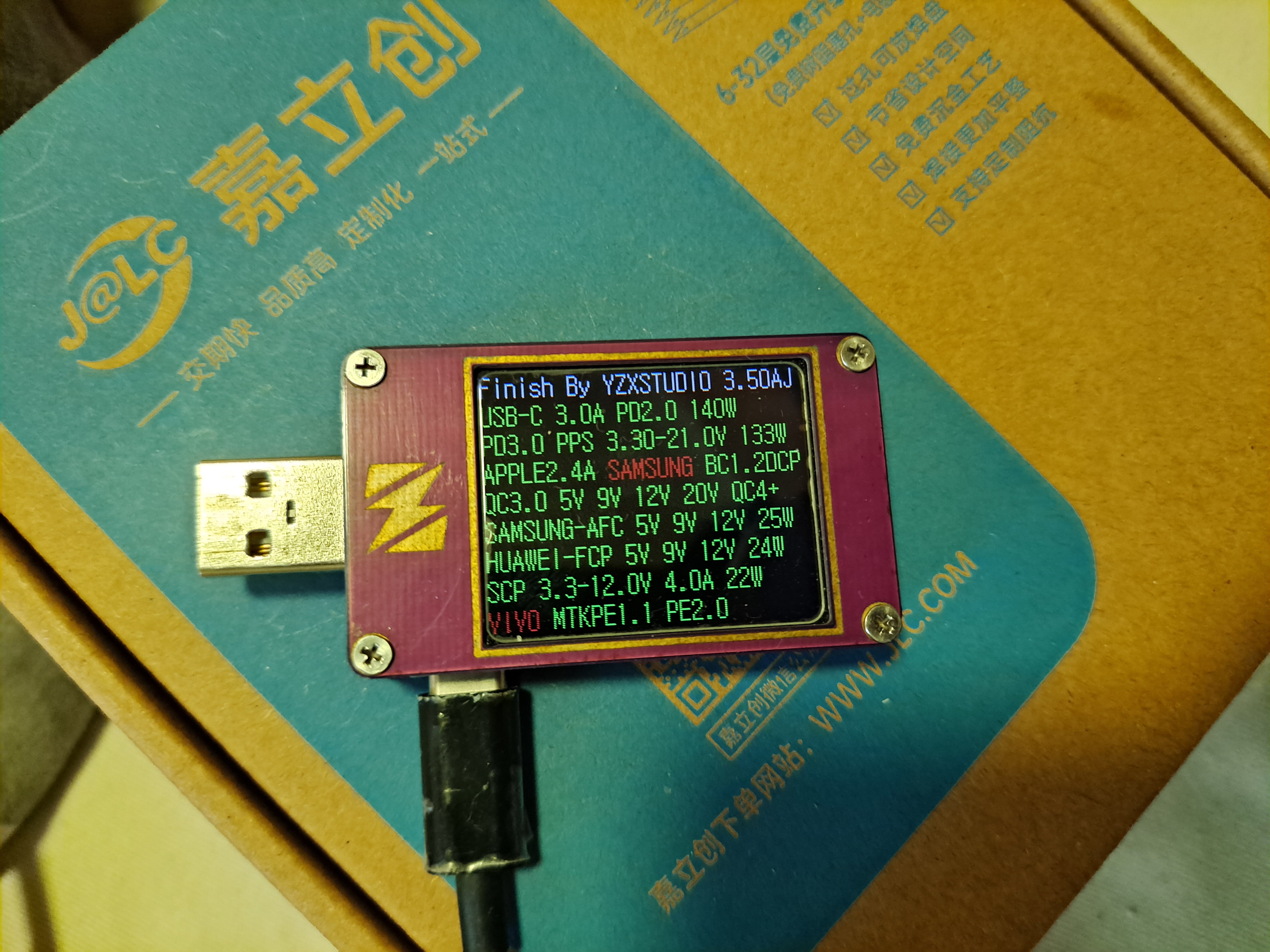 C2 and C3 port protocols:
 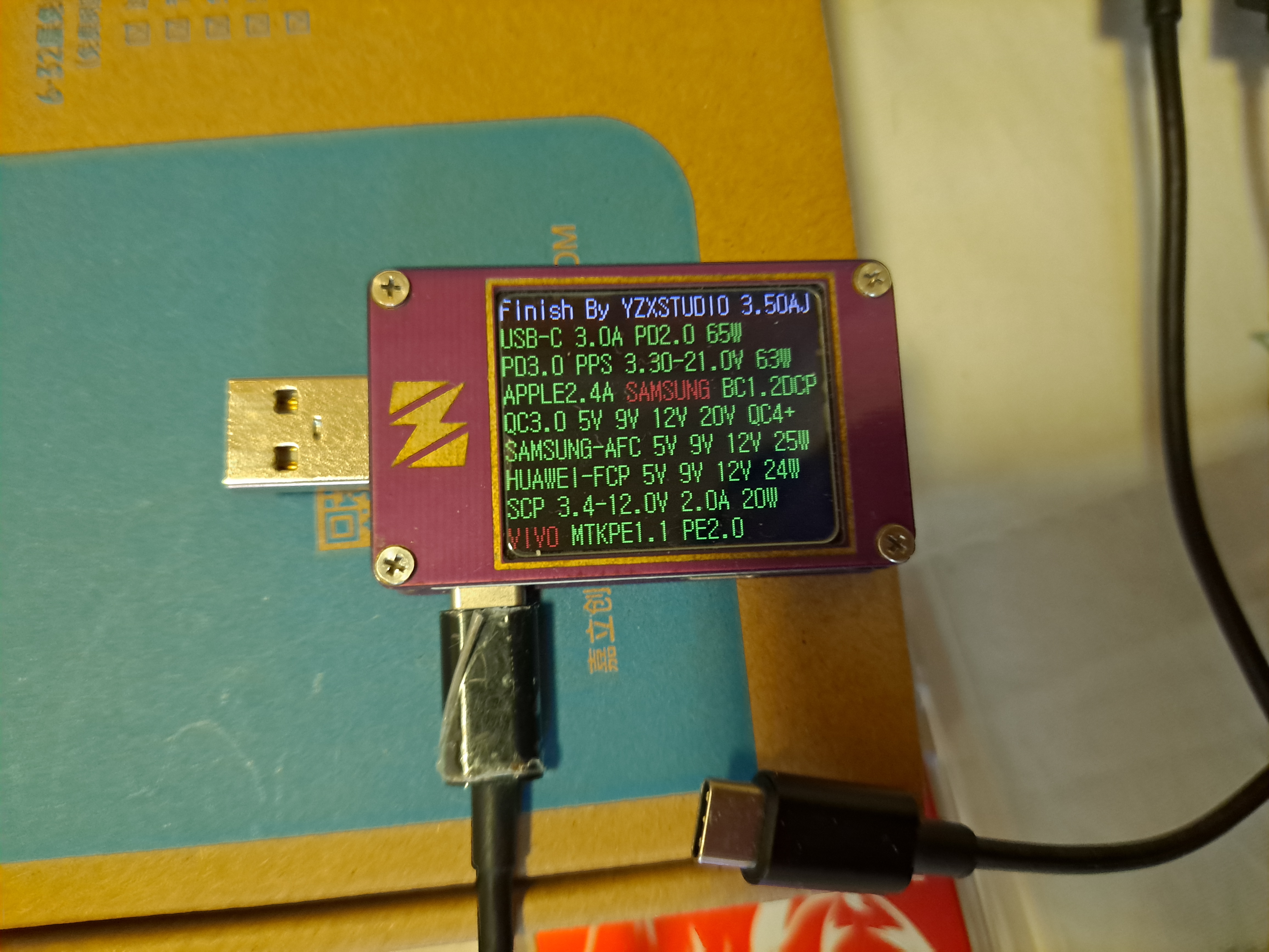 The components already soldered in this diagram are surface-mount; the rest are through-hole components. Close-up of
  the three inductors: 1770 package inductors cost 3.5 yuan each, and 1265 package inductors cost less than 1 yuan each.
 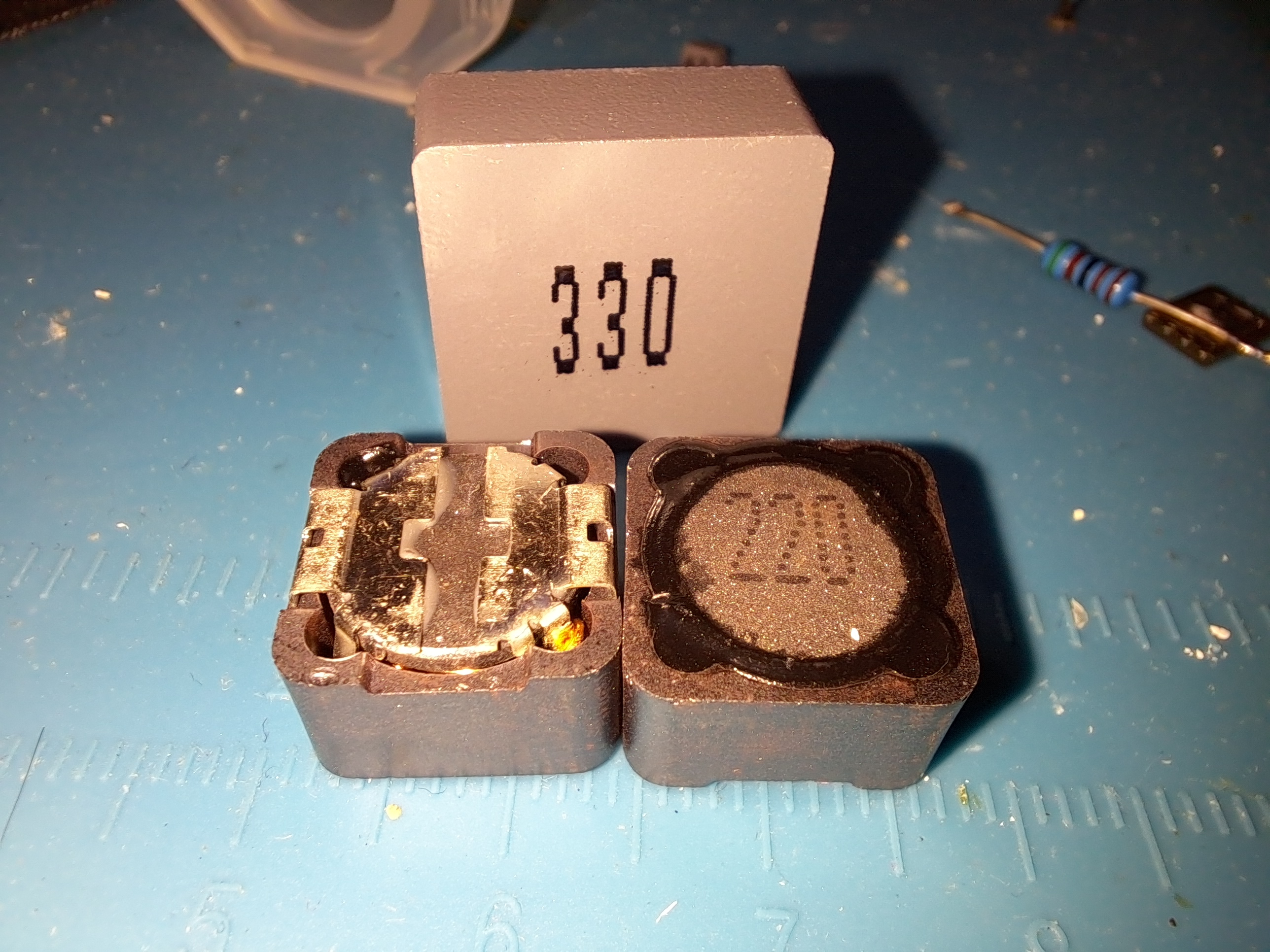 The sample I have is being tested. The SW3538 uses an AON6144 switch, the output path switch uses an SI7686DP, and the main input reverse connection protection switch is an FQD60N06. The MOSFET junction capacitance is relatively large; at 200W output, the highest temperature is around 50-60 degrees Celsius.
 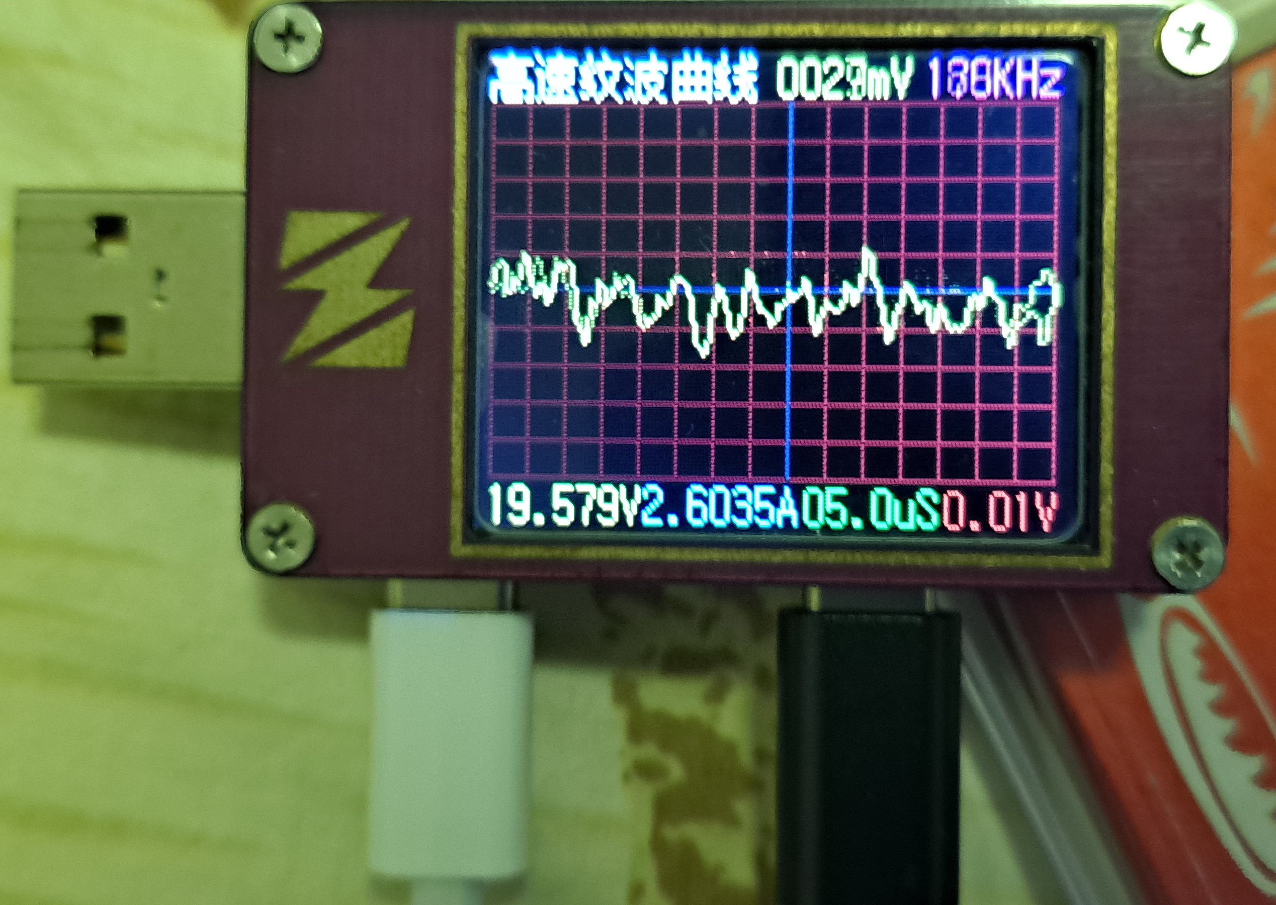 Power testing: The power output is normal according to the USB meter. The highest continuous output at port C1 was tested at around 120W without problems; higher power outputs could not be tested. With a 24V input, the highest measured power of the entire unit was 200W, with an input current exceeding 8.3A. At this point, using a DC5525 input with 18AWG wire resulted in significant heat generation.
  Hardware bug: The fast charging indicator light on the 3538 chip is faulty; the FLED interface cannot be pulled low, causing it to remain off. I've tried two chips with the same issue, so I'm not bothering with it; it doesn't affect usage. The fast charging indicator light on the SW3526 works fine.
All reference designs on this site are sourced from major semiconductor manufacturers or collected online for learning and research. The copyright belongs to the semiconductor manufacturer or the original author. If you believe that the reference design of this site infringes upon your relevant rights and interests, please send us a rights notice. As a neutral platform service provider, we will take measures to delete the relevant content in accordance with relevant laws after receiving the relevant notice from the rights holder. Please send relevant notifications to email: bbs_service@eeworld.com.cn.
It is your responsibility to test the circuit yourself and determine its suitability for you. EEWorld will not be liable for direct, indirect, special, incidental, consequential or punitive damages arising from any cause or anything connected to any reference design used.
Supported by EEWorld Datasheet
EEWorld
subscription
account

EEWorld
service
account

Automotive
development
community

Robot
development
community

About Us Customer Service Contact Information Datasheet Sitemap LatestNews


Room 1530, 15th Floor, Building B,
No.18 Zhongguancun Street,
Haidian District,
Beijing, Postal Code: 100190
China
Telephone: 008610 8235 0740
 京公网安备 11010802033920号

 AME8501CEFTBF46


