Video Links:
A "Desktop Control Console" Composed of a Serial Port Screen and ESP32, Costing Only a Few Tens of Yuan - Bilibili
Host Computer Software Code (Please feel free to discuss any unclear points)
https://gitee.com/lsy330586/ESP32-python.git
Microcontroller Code
https://gitee.com/lsy330586/esp32-serial_port_screen.git
Project Introduction
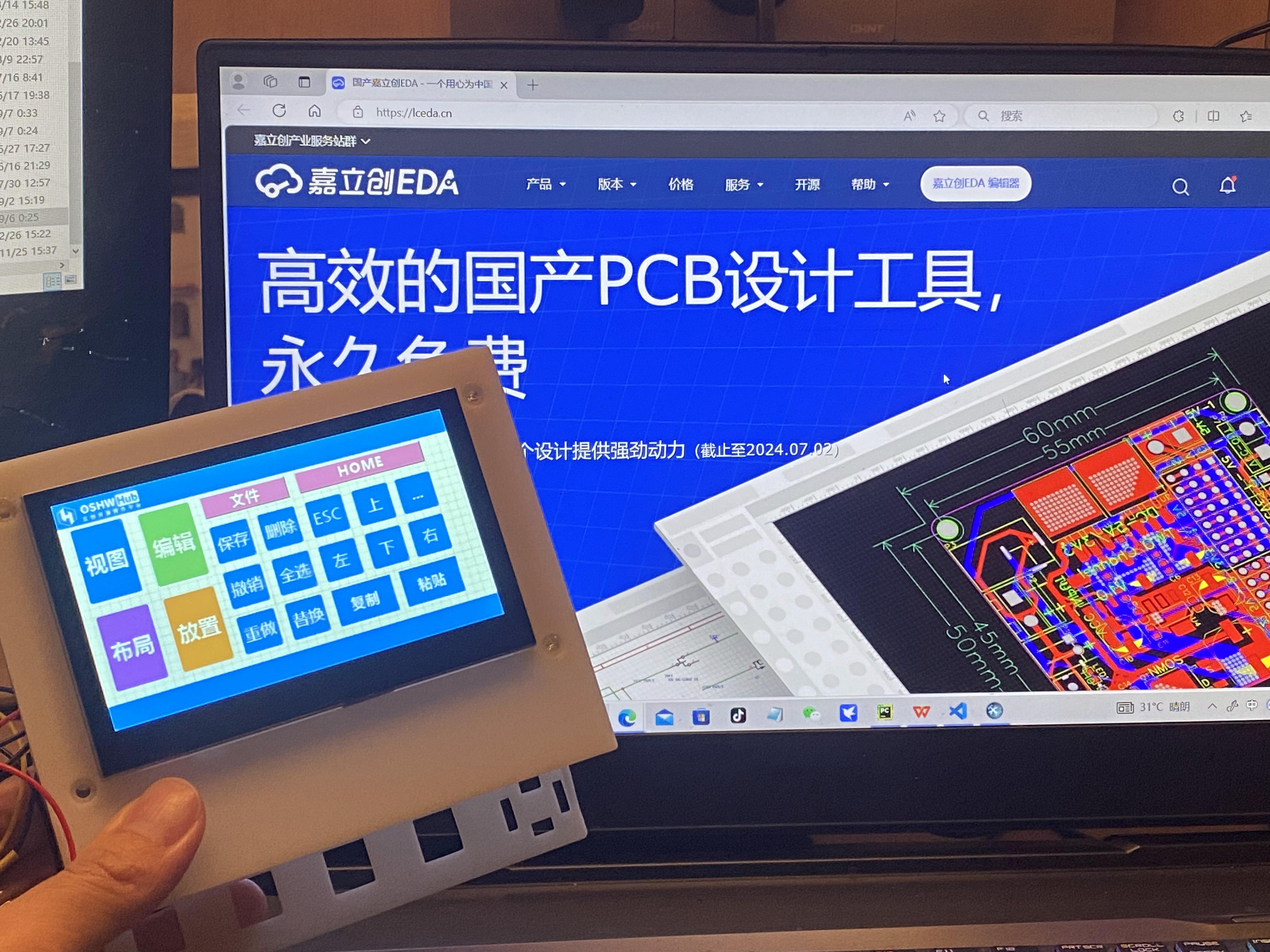

This project builds a "central control console" based on the ESP32-S3 chip and a Taojingchi serial port screen.
The main reason for choosing this chip and serial port screen is its simple hardware design, which can shorten the development cycle of the HIM and microcontroller programs, allowing us to focus more on the development of the host computer software.
It's worth mentioning that AI plays a significant role in the development of the microcontroller and host computer programs;
the circuit part and the serial port screen are not complex, anyone can do it!
The project
currently supports the following functions:
Touchscreen buttons: Open computer software, log in to websites, shortcut keys (customizable) such as keyboard AZ, combination keys: "CTRL+C", "CTRL+V", "SHIFT+TAB".
Application scenarios:
Customized shortcut keys: "LCSC EDA shortcut keys", "CapCut shortcut keys", "TikTok Live Companion", "OBS", "keil_5", etc. ...
I will upload video tutorials in the
future. Future implementations include:
Smart furniture central control, voice input AI to text conversion, universal remote control function...
Implementation principle:
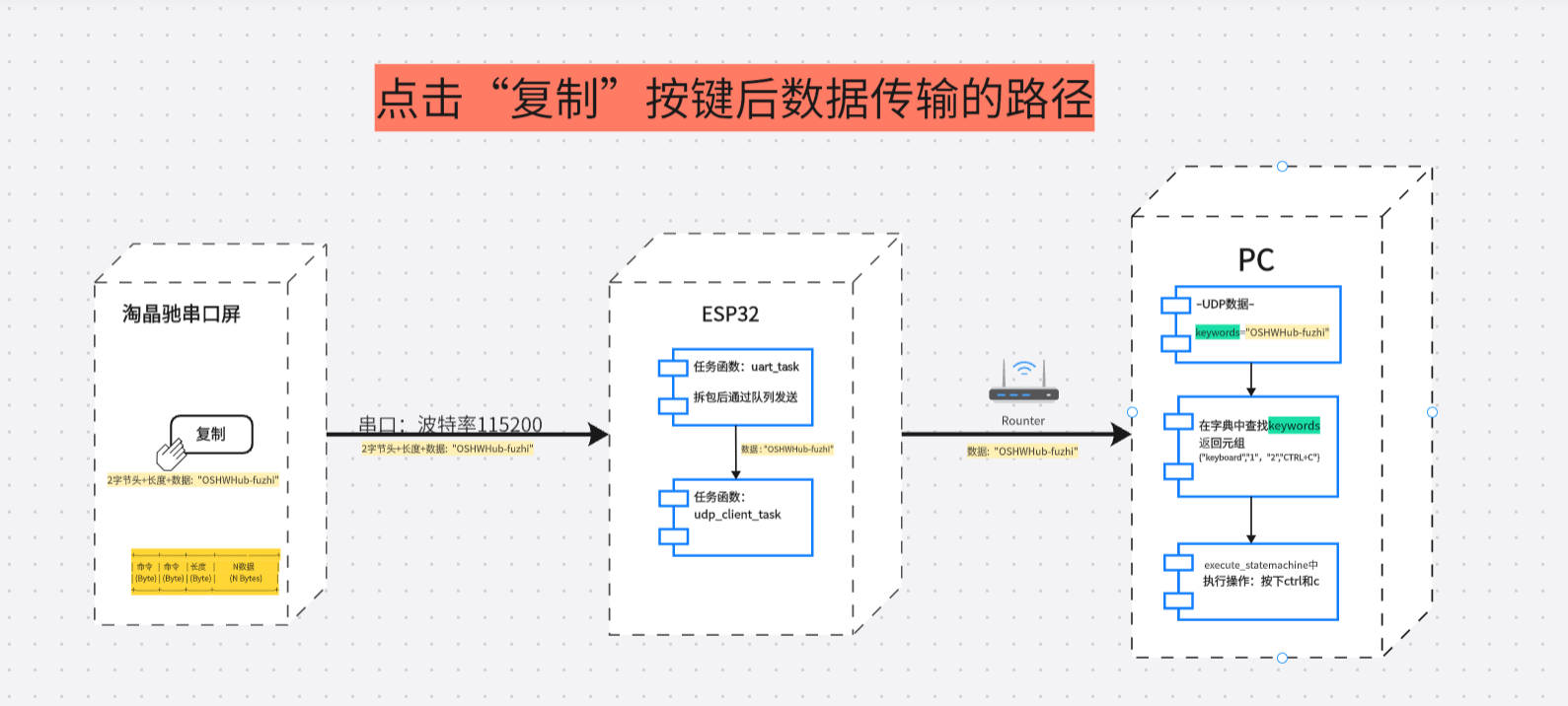
Data flow Image 1:
Taking pressing the "copy" key as an example
Protocol:
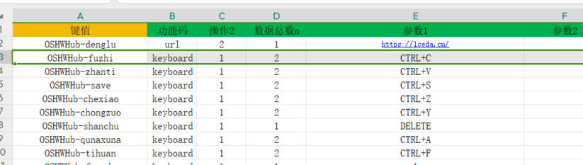
Python dictionary {}
Key: Key
Value: {"Function code", "Operation", "Total data n", "Parameter 1", "Parameter 2", "Parameter 3"}
1. It is worth mentioning that the data sent by the button (serial port screen)
2. ESP32 receives the serial port data and then forwards it to the host computer via UDP
3. The host computer receives the data;
3. Compare the following key values in the host computer's "dictionary";
if found, return a tuple {"function code", "operation", "total data n", "parameter 1", "parameter 2", "parameter 3"}.
Taking "copy" as an example, the key value is **"OSHWHub-fuzhi"**. Return {"keyboard", "1", "2", "CTRL+C", " ", "}}.
- "function code": keyboard represents simulated keyboard operation, and can also be url / openfile / pccontrl..... etc., which can be customized;
**- "operation":** The number "1" represents pressed, and can also be defined as long press, short press, etc.
- "total data n": "2" is (not the number of parameters), because two key values CTRL and 'C' are pressed;
- "parameter 1": two key values
- "parameter 2": omitted
- "parameter 3": omitted
item parameter
1.
Main control chip: adopts ESP32S3 series chip, based on FreeRTOS operating system, supports rapid UDP development.
2.
Display: Uses a Taojingchi serial port display with official HMI software, providing a graphical interface to simplify the development process of functions such as buttons, sliders, and text boxes; baud rate is 115200; only a small amount of very simple logic code is needed, as many functions are already integrated and encapsulated, making it very powerful.
3.
Mechanical Keyboard: Integrates specific mechanical keys, suitable for frequently used operations such as copy, paste, spacebar, etc., improving operational efficiency.
4.
Encoder: Employs an EC11 encoder, suitable for adjusting continuously changing parameters, such as volume, brightness, and zoom.
Principle Analysis (Hardware Description)
This project consists of the following parts: power supply, LCSC ESP32S3 main control development board, button circuit including blue axis mechanical buttons, EC11 encoder,
gyroscope, and Taojingchi serial port screen
. The most important parts are the ESP32 development board and the Taojingchi serial port screen.
The development board provides Wi-Fi connection, control, and data transmission functions, and can process the data from the serial port screen and send it to the computer via TCP/IP.
The Taojingchi serial port can quickly build buttons and program them via serial port...
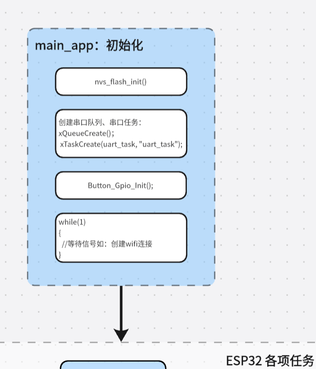
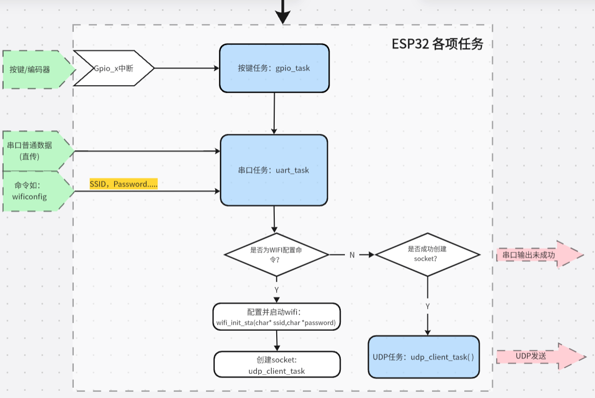
ESP32 software flowchart:
Python function flowchart:

Hardware circuit
example diagram 1 -- Mechanical button circuit:
A 10K pull-up resistor raises the GPIO pin to 3.3V. The microcontroller detects whether the button is pressed through a falling edge interrupt of the GPIO.
I tried to reduce interrupts from the hardware side. I added a 5pF capacitor between the GPIO input pin and GND for debouncing.
Other tutorials give 100nF (0.1u), but after testing, I found that 5pF-10pF works best? Is this how mechanical buttons are supposed to be? I haven't bought an oscilloscope yet, so I'd appreciate some advice...
Regarding the effect: the mechanical buttons bounce 40-50 times after being pressed. After adding a capacitor, the bounce is reduced to 5-10 times per press, a significant debouncing effect. A short 50ms delay in the software further eliminates the bounce.
Based on my testing, the power supply also significantly affects the button's bounce; the bounce varies depending on the USB port on the same computer...

Example image 2 -- EC11 Rotary encoder circuit: This example circuit

was built according to the official reference.
Example Figure 3 – ESP32S3R8N8 development board: The circuit
uses the development board recommended by LCSC. Since this version uses jumper connections, the selection of I/O ports is relatively flexible and can be modified at any time.

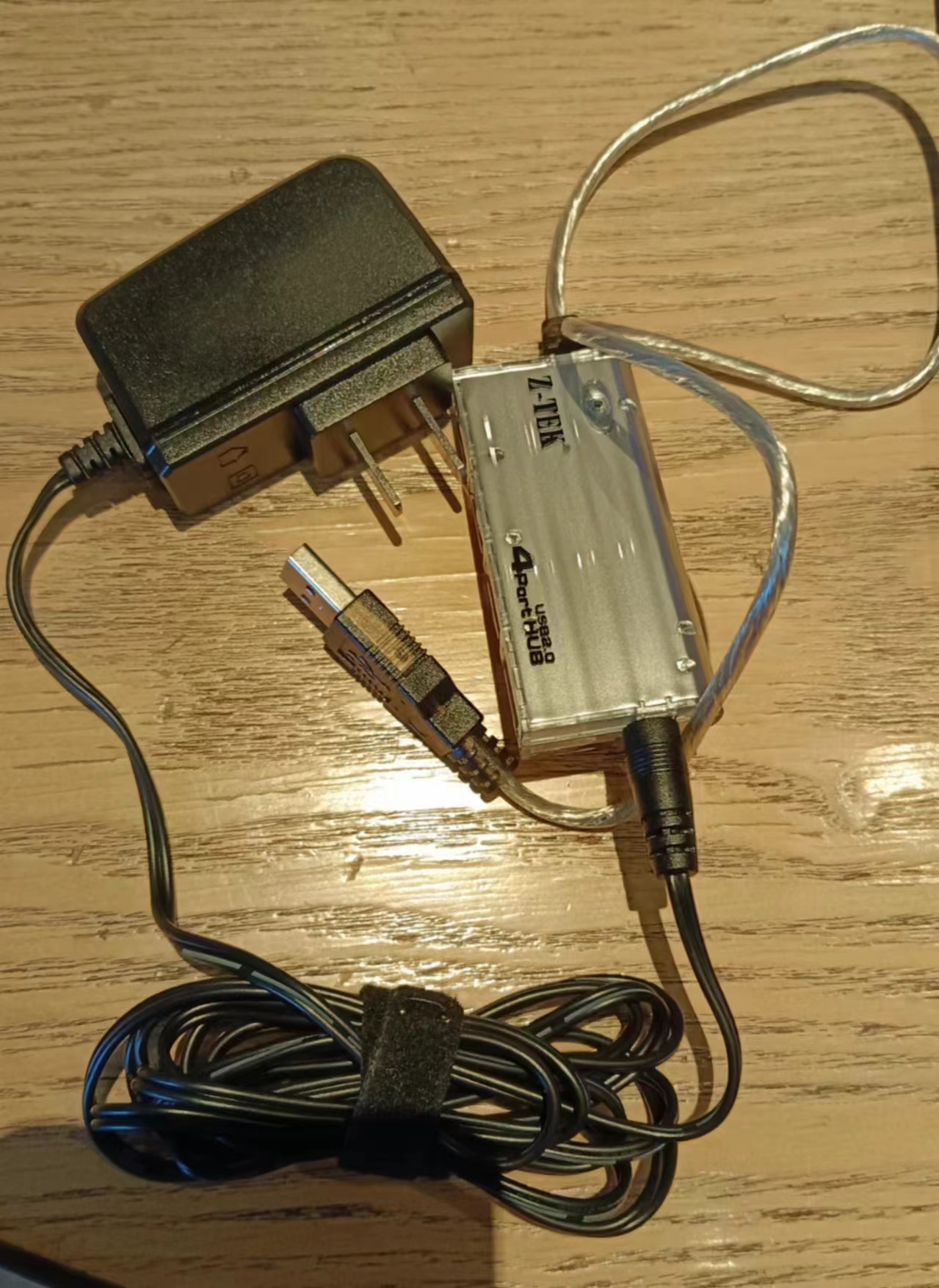
Example Figure 4 – Power supply circuit:
We'll use the existing power supply for now and create our own in the next version. The Wi-Fi chip itself is quite power-intensive, and there's also a microcontroller on the serial port screen, so the power supply needs to be stable.
Example Figure 5 – Serial port screen

circuit: The official schematic and circuit for the serial port screen are provided. The screen inherits a microcontroller chip.
Example Figure 5 – Shell:
Host computer software code
: https://gitee.com/lsy330586/ESP32-python.git
Microcontroller code
https://gitee.com/lsy330586/esp32-serial_port_screen.git
Serial Port Screen Creation Tutorial ***
1. Create Protocol
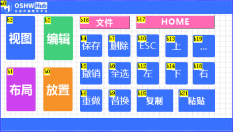
2. Drag in Buttons, Write a Line of Code for Each Button:
printh ......
2-2. Configure WiFi: wificonfig with keyboard
selection (Keyboard A)
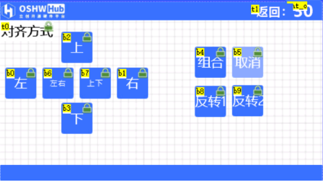
2-3. Place Resistors and Capacitors Page Creation, Add Timer for Exit
3. Beautify Buttons and Background;
Arrange Them
4. Add Small Functions


 京公网安备 11010802033920号

 MD83C151C-25


