Project Description:
Adhering to the principle of minimizing costs and providing ease of secondary development for F427 flight controller enthusiasts (PX4), this project open-sources a flight controller based on the STM32F427 microcontroller. It supports open-
source protocols for multi-rotor aircraft, helicopters, fixed-wing aircraft, unmanned surface vessels/vehicles, underwater robots, VTOL (Vertical Take-Off) systems, etc.
This hardware design is released under the GPL 3.0 license for DIY learning and exchange purposes only; any form of commercial use is strictly prohibited.
Project Functionality:
A drone controller based on the STM32F427 main controller and the STM32F100 auxiliary chip.
This module is the control board for the flight controller; all ports are exposed for secondary development, enabling low-cost drone implementation.
Specific functions:
1. Main controller: STM32F427VIT6, auxiliary controller: STM32F100C8T6
2. Onboard MPU6000 gyroscope
3. Onboard MS5611-01 barometer
4. Onboard triaxial angular velocity sensor: L3GD20TR
5. Onboard triaxial accelerometer: LSM303D
6. Onboard FM25V01A-GTR
7. Supports 4 serial ports (originally 5, one of which is used for auxiliary chip communication)
8. Supports external SD card for the black box
9. PWM output channels: 14 PWM channels (6 main channels, 8 auxiliary channels)
10. Direct-plug SWD download interface
11. Most components use SH1.0 interface; GPS and current/voltmeter components use SH1.25 interface, no interface replacement required
12. 11. Reset button;
12. Supports OSD and data transmission
; 13. SPI bus and CAN bus
; 14. Analog-to-digital converter (ADC) 6.6V and 3.3V.
Project Progress:
2024/02/01 -- 2024/02/20 Completed the hardware design of this flight controller using JLCPCB Professional Edition.
2024/02/21 -- 2023/05/31 Prototyping and learning PX4 firmware, soldering, and bug finding.
Design Notes:
1. The smallest package of this flight controller is 0603, which can be hand-soldered with a soldering iron without any problems. Before powering on, check for short circuits at the power supply. It is recommended to debug while soldering, rather than soldering the entire package first and then debugging.
2. For the hardware, after confirming that the soldering is correct, first use ST-link to burn the bootloader to the two chips. Then, connect the computer via USB cable, and it will be recognized. After that, you will not need to use ST-link to download programs again.
3. For firmware, you need to edit the PX4 environment in Ubuntu. Then you can download the firmware using the command line in the virtual machine, or export the firmware and burn it to the QGC ground station. For takeoff, you need to configure it on the QGC ground station.
Attachments: (For questions, add QQ: 517271058)
1. Bootloaders for STM32F427VIT6 and STM32F100C8T6
2. Source code (the PX4 official website is constantly updated; I uploaded version 1.14.0)
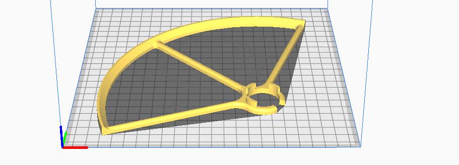
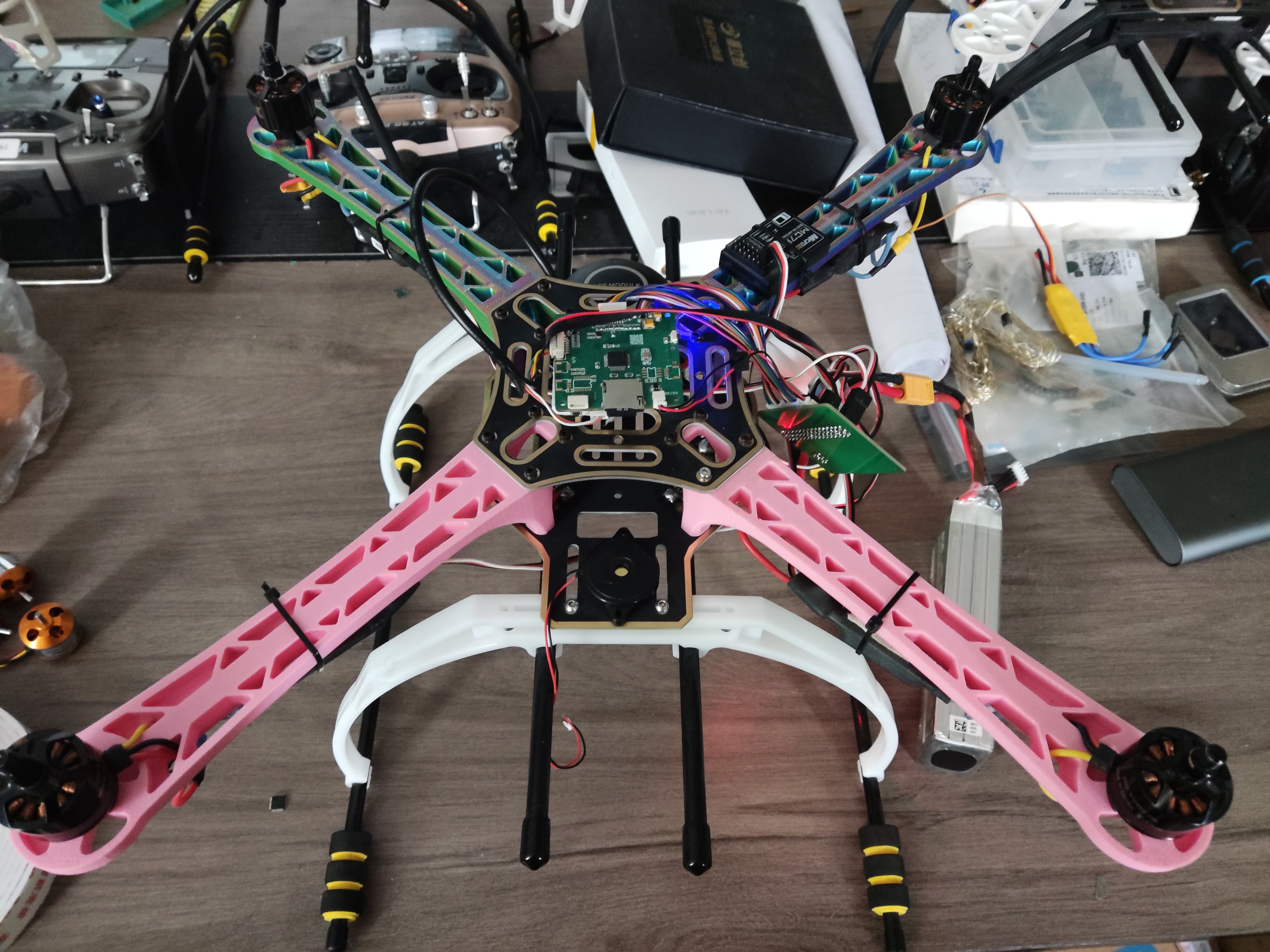
3. Printed parts of the F450 frame, and a complete F450 frame (but not recommended to print out; "viewable from a distance")
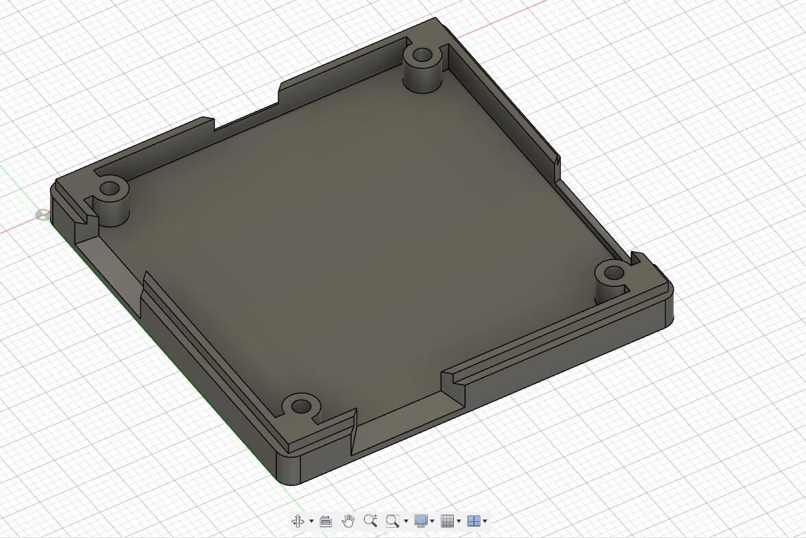
4. The casing of this flight controller board
5. Demo video: https://www.bilibili.com/video/BV1Xtg5ejES6/?spm_id_from=333.999.list.card_archive.click


 京公网安备 11010802033920号

 25.180.5653.0


