//Re-uploaded a new version. It's time to do my graduation project, and many people have asked questions.//
Heart disease is one of the leading causes of death in humans. Timely and accurate electrocardiogram (ECG) monitoring is crucial for the prevention and diagnosis of heart disease. However, due to the sudden and random nature of cardiac abnormalities, short-term monitoring often fails to capture abnormalities, leading to misdiagnosis. Furthermore, traditional ECG monitoring equipment is usually expensive and inconvenient, failing to meet people's daily monitoring needs.
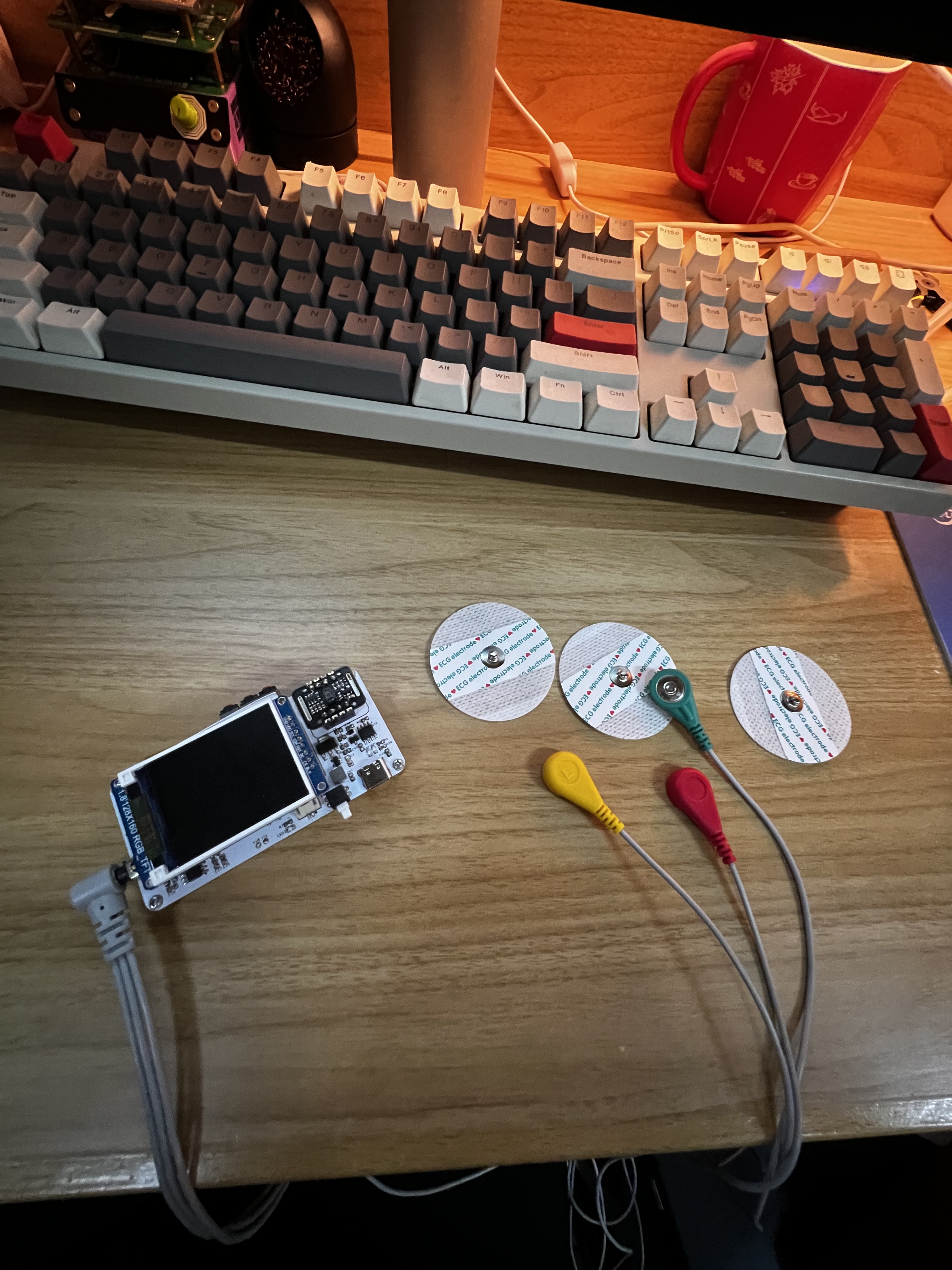
Therefore, developing a small, portable ECG monitor that allows users to monitor their ECG anytime, anywhere is of significant practical importance.
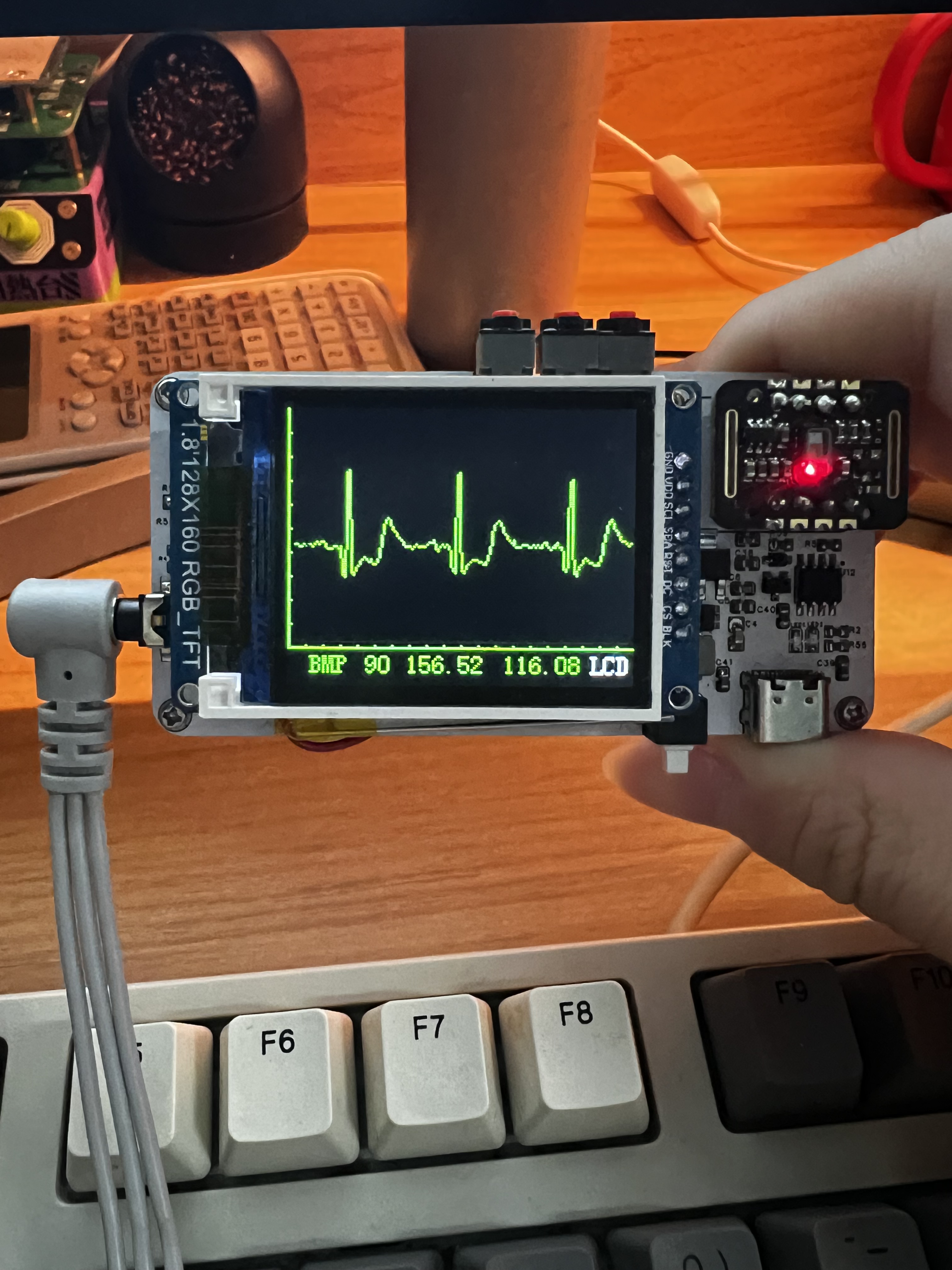
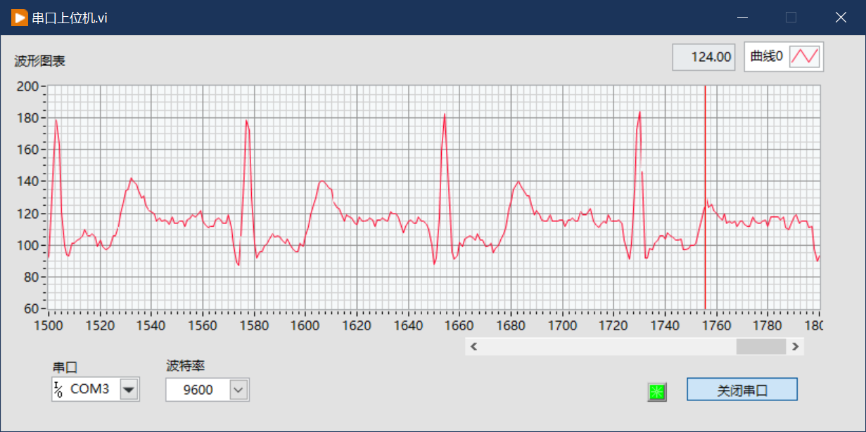
Displays real-time ECG waveforms and calculates heart rate. It can also measure blood oxygen saturation.
It can switch between lower-level screen display and Bluetooth transmission of waveform data to the upper-level computer.
Warnings for tachycardia and bradycardia.
The frequency range of ECG signals is mainly concentrated in the range of 0.05~100Hz, with a voltage of about a few tenths of a millivolt. It has the characteristics of being weak, low-frequency, and easily interfered with. Common types of interference include:
1. Power frequency interference. Interference caused by the power supply network (usually 50Hz) is a major source of interference in ECG signals.
2. Baseline drift. Changes in the ECG baseline caused by respiration and exercise can result in amplitude variations of up to 15%, with low frequency.
3. Electromyographic interference. Muscle activity is accompanied by electrical activity. Its frequency range is 20–5000Hz.
First stage preamplifier, gain 7, includes right leg drive circuit, used to eliminate common mode interference.
Second stage 107HZ low-pass filter, eliminates high frequency signals.
Third stage dual-T active 50HZ notch filter, filters out power frequency interference.
Fourth stage 0.1HZ high-pass filter, improves baseline drift, amplifies 50 times.
Fifth stage amplifier amplifies the signal 5 times.
Overall, the signal is amplified 1250 times. The microcontroller is reset at low level
pin P54 for software programming. It is powered
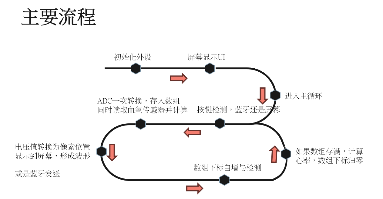
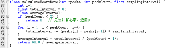
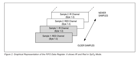
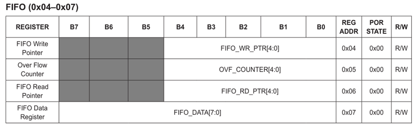
by 3V3. USB and lithium battery. The USB interface uses the widely used Type-C battery. The battery is an 850mA 3.7V lithium battery. After inserting the USB cable, it can automatically switch to USB power supply and charge the lithium battery at the same time. Battery charging management uses TP4056 chip. Software design: Heart rate calculation: Heart Rate (bpm) = 60 / average R wave interval (seconds). R wave detection method – threshold method: 1. Traverse the data: Traverse each data point in the ECG data array. 2. Peak Condition: For each data point, check if it is greater than the data points on the left and right, and if it exceeds the preset threshold. 3. Record Peak: If the data point meets the above conditions, record its position, indicating that an R-wave peak has been detected. Advantages: Simple, fast Disadvantages: Inaccurate, and the threshold needs to be determined manually. If baseline drift or noise spikes occur, it will have a significant impact. Waveform Drawing Implementation : Calculate and scale the voltage value to the Y-axis coordinate value of the screen pixels, and use the X-axis as the time axis . Draw one pixel for each ADC value, and draw a straight line connecting adjacent points. The final effect is a real-time voltage waveform scrolling refresh. Blood Oxygen Saturation Reading: 1. Initialization: Initialize the MAX30102 sensor, including configuration mode, sampling rate, LED current, and other parameters. 2. Data Acquisition: Read the intensity data of red and infrared light from the sensor's FIFO Data register via I2C. Each data point consists of three bytes and needs to be merged into a single long integer. 3. Calculation: Blood oxygen saturation is calculated using a simplified formula based on red and infrared light data. The simplified formula is : R = red / ir spO2 = 120 - 25 * R. Accurate calculation of blood oxygen saturation requires obtaining both the DC and AC components of the light intensity, which involves a large amount of computation and storage. The simplified formula may not yield accurate results. The host computer is based on LabVIEW and only has basic waveform drawing functionality. Demonstration video link: https://www.bilibili.com/video/BV1mJ8qeSEuj/?vd_source=51dc43e08b25c112cfd71690f421341d
This is a mini STM32F411RET6 development board, smaller than the palm of your hand. It can be used for AI development, UI development, digital power control boards, and even for your graduation project and other related projects.
FryPi
STM32F411RET6 Development Board


Introduction:
This is a mini STM32F411RET6 development board, smaller than the palm of your hand. The core board cost is under 60 RMB. It can be used for AI development, UI development, digital power control, and even for your graduation project and other related projects.
The initial purpose of creating this board was for my previous smartwatch project, OV-Watch. Many people who replicated it said that many components were very difficult to solder, especially the main controller, which was too small, making secondary development inconvenient. In addition, I also planned to deploy AI-related things on STM32 and create tutorials. Therefore, FryPi was born. This development board is suitable not only for beginners but also for advanced developers. Advanced routines in projects may require a certain level of knowledge.
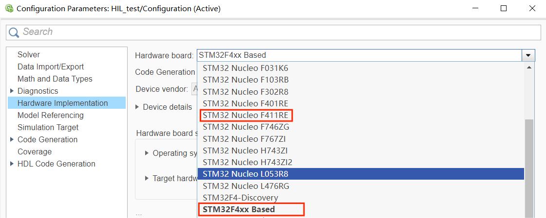
The reason for choosing this MCU is that the STM32F411RET6 can perfectly replace the CEU6 in the original smartwatch project, and there is also a hardware option for the F411 in Simulink.
Features:
The MCU uses an STM32F411RET6, a Cortex-M4 core with DSP and FPU, 512 Kbytes of Flash memory, a 100 MHz CPU, and an ART Accelerator.
An external SPI Flash can be soldered on.
Abundant example programs are available, including advanced examples such as smartwatch, thermal imaging gesture recognition, handwritten digit recognition, MATLAB co-development, Simulink-in-the-loop development, etc.
Ports are provided for connecting external expansion boards (e.g., the animated demonstration at the top shows a CAM expansion board plugged into the Core board).
Both dual-TypeC and single-TypeC versions of the Core board are available.
The FryPi pin map is shown below; currently, only some I/O ports are used for peripherals such as LCDs and touchscreens.

Hardware Description: The current hardware engineering version is V1.1, consisting of one Core board, one single-TypeC Core board, one CAM expansion board, and one OV2640 camera module, which can be purchased online. The 3D schematic of the Core board is shown below. We hope you will feel free to explore and create expansion boards, such as a sensor expansion board, or directly plug it into a car.

The software documentation includes the following example demos, which are presented in the directory below. The demos are plentiful, divided into Basic and Advanced examples. For details, please click the link or view them directly in the GitHub repository.
Basic
0.template
1.GPIO
2.USART
3.TIM
4.PWM
5.ADC
6.SPI
7.LCD
...todo
Advanced
0.FreeRTOS template
1.How to use CubeAI
2.Handwritten digit recognition
3.Thermal imaging gesture recognition
4.Using VScode EIDE plugin
5.Simulink in-the-loop development
6.LVGL smartwatch
7.OV2640 camera + recognition
...todo
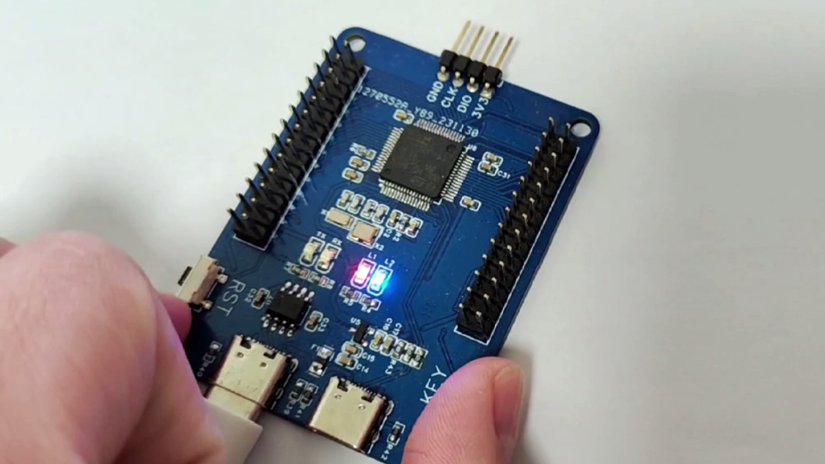
On-machine testing
After the development board is soldered and you receive it, burn the template routines and observe the phenomenon. If there is no problem with the hardware, then when you plug the serial port into the corresponding Type-C port to connect to the computer, L2 will flash. Press the key to switch modes, and the flashing frequency of L2 will change. At the same time, the host computer will receive the mode information.

If you plug the development board into the USB corresponding Type-C port to connect to the computer, the computer will prompt you to format the USB drive. After formatting, it will simulate a USB drive.

This section provides a partial example
using thermal imaging gesture recognition as a demo project (for other detailed examples, please refer to GitHub):
I. Folder Structure
├─python_codes
│ │ data_2_imgfile.py
│ │ data_get.py
│ │ data_show.py
│ │ gesture.h5
│ │ test.py
│ │ train.py
│ │
│ └─camera_data
│ test_data.npz
│ train_data.npz
│
└─stm32_codes
├─ThermalCamera_data_send
├─Thermalgesture
The folder structure is roughly as shown above. `python_codes` contains code for acquiring data from the lower-level machine, network training, and testing. The collected thermal imaging data is saved in .npz format files for network training and testing, while the model is saved in .h5 format. `stm32_codes` stores STM32 code. The first part contains the raw thermal imaging data obtained by LCD screen refresh and serial port transmission of fried chicken pie. The second part contains the already deployed thermal imaging gesture recognition code.
II. Thermal imaging streaming to the screen
directly uses the provided MLX90640 API, with corresponding changes to the I/O ports. See the code for more detailed information. To speed up screen refresh, the `drawPicture(void)` function in `mlx90640_display_process(void)` uses a buffer for screen refresh, as dot-mapping refresh is too slow. See the code for details.

III. Convolutional Neural Network Setup, Training, and Deployment
1. CNN Setup and Training
The convolutional neural network setup is shown in the figure below. The training set contains approximately 4000 image arrays. `num_epochs` is set to 50, `batch_size` is set to 64, and the Adam optimizer's `learning_rate` is set to 0.01. The final Acc can exceed 0.9. See `./python_codes/train.py` for detailed network setup.
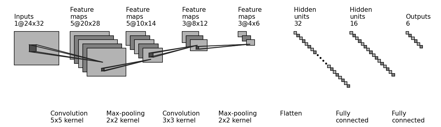
The following shows how to build a CNN model using Keras. For other related code, please refer to the Python code.
#------------------------------【Building the Model】---------------------------------
model = tf.keras.models.Sequential([
tf.keras.layers.Conv2D(filters=5, kernel_size=(5, 5), padding='valid', activation=tf.nn.relu, input_shape=(24, 32, 1)),
tf.keras.layers.MaxPool2D(pool_size=(2, 2), padding='same'),
tf.keras.layers.Conv2D(filters=3, kernel_size=(3, 3), padding='valid', activation=tf.nn.relu, input_shape=(10, 14, 5)),
tf.keras.layers.MaxPool2D(pool_size=(2, 2), padding='same'),
tf.keras.layers.Flatten(),
tf.keras.layers.Dense(units=32, activation=tf.nn.relu),
tf.keras.layers.Dense(units=16, activation=tf.nn.relu),
tf.keras.layers.Dense(units=6, activation=tf.nn.softmax)
])
model.summary()
2. Deploying the CNN to STM32
First, after generating code for the trained gesture.h5 model using the CubeMX AI tool, call the API. Here, the main function used is ai_mnetwork_run(), specifically the function user_ai_run(const ai_float *in_data, ai_float *out_data) in the following code block. Since CubeMX selects systemperform for code generation, MX_X_CUBE_AI_Process() should be commented out. This is mainly used to test the model's performance, and it uses random numbers to fill the input by default.
uint8_t user_ai_run(const ai_float *in_data, ai_float *out_data)
{
int idx = 0;
int batch = 0;
ai_buffer ai_input[AI_MNETWORK_IN_NUM];
ai_buffer ai_output[AI_MNETWORK_OUT_NUM];
ai_float input[1] = {0};
ai_float output[1] = {0};
if (net_exec_ctx[idx].handle == AI_HANDLE_NULL)
{
printf("E: network handle is NULL
");
return -1;
}
ai_input[0] = net_exec_ctx[idx].report.inputs[0];
ai_output[0] = net_exec_ctx[idx].report.outputs[0];
ai_input[0].data = AI_HANDLE_PTR(in_data);
ai_output[0].data = AI_HANDLE_PTR(out_data);
batch = ai_mnetwork_run(net_exec_ctx[idx].handle, ai_input, ai_output);
if (batch != 1) {
aiLogErr(ai_mnetwork_get_error(net_exec_ctx[idx].handle),
"ai_mnetwork_run");
return -2;
}
return 0;
}
Note that the input data I provided here has been normalized, as shown in the following code.
static void normalizeArray()
{
float range = maxTemp - minTemp;
for(uint16_t i=0; i<24*32; i++) {
normalizetempValues[i] = (tempValues[i] - minTemp) / range;
}
}
The output data format is an array of length 6, corresponding to no gesture and gestures 1~5 respectively. The category judgment condition is to select the largest number, that is, to judge which number is the largest, and the corresponding gesture is judged as the current gesture. The following code finds the index corresponding to the largest number.
static uint8_t findMaxIndex(float arr[], uint8_t size) {
if (size <= 0) {
// Handle the case of empty array or invalid size
return -1;
}
uint8_t maxIndex = 0; // Assume that the index of the maximum value is the index of the first element
for (int i = 1; i < size; ++i) {
// Check if the current element is greater than the current maximum value
if (arr[i] > arr[maxIndex]) {
maxIndex = i; // Update the index of the maximum value
}
}
return maxIndex;
}
Finally, the entire recognition process is given as follows.
normalizeArray();// Normalize first
if(user_ai_run(normalizetempValues, outputs))// Substitute the normalized data and perform forward calculation
{
printf("
run error
");
}
uint8_t temp = findMaxIndex(outputs, sizeof(outputs) / sizeof(outputs[0]));// Find the index of the maximum value
printf("
predict gesture:%d
", temp);// Print the judged gesture
Of course, the above is just one of the demos. For more basic and advanced routine demos, please refer to the GitHub repository.
Purchase List: 1. Touchscreen Model: Search P169H002-CTP on Taobao.

2. STM32F411RET6: I usually buy from Youxin Electronics.
3. Others: For convenience, I usually buy other resistors and capacitors directly from LCSC.
Demo Video
(Bilibili Link): https://www.bilibili.com/video/BV1u2421F7kf/
Code Repository
(GitHub): https://github.com/No-Chicken/FryPi.
Gitee: https://gitee.com/kingham/FryPi.
There are many demo projects in the software section on GitHub, and I've written detailed descriptions of them, so I suggest you check the code and demo tutorials directly on GitHub. If you can't open the repository, you can find a GitHub mirror online, use a VPN, or search for me on Gitee.
Tutorial
website: https://no-chicken.xyz
Basic tutorial videos: https://www.bilibili.com/video/BV1Gy411e7EH
Advanced tutorial videos: https://www.bilibili.com/video/BV1nw4m1e7TJ
QQ groups :
Group 1: 572216445
Group 2: 912218004
 Requirements Analysis
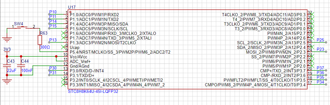


 京公网安备 11010802033920号

 CL10C010CB81PNF


