
Do you remember the V3S development board that was released some time ago? Since hardware decoding could not be completed, the author found a newly released chip from Allwinner
, the T113-S3. This chip uses a dual-core A7, supports the Tina Linux SDK provided by Allwinner, and has complete documentation. After a period of adjustment, the project is now ready for mass production.
Update Log
2024-04-27 V5 verification completed, updated Tina 5.0 test image t113_linux_pi_uart0_480.img
2024-03-29 Updated build manual, updated SD card, SPI Nand image, fixed boot logo issue, added communication group
2024-03-21 Updated build manual, updated SD card, SPI Nand image, officially supports SPI Nand
2024-02-13 Documentation created
2024-01-24 Project initiation,
communication group established

Project Description
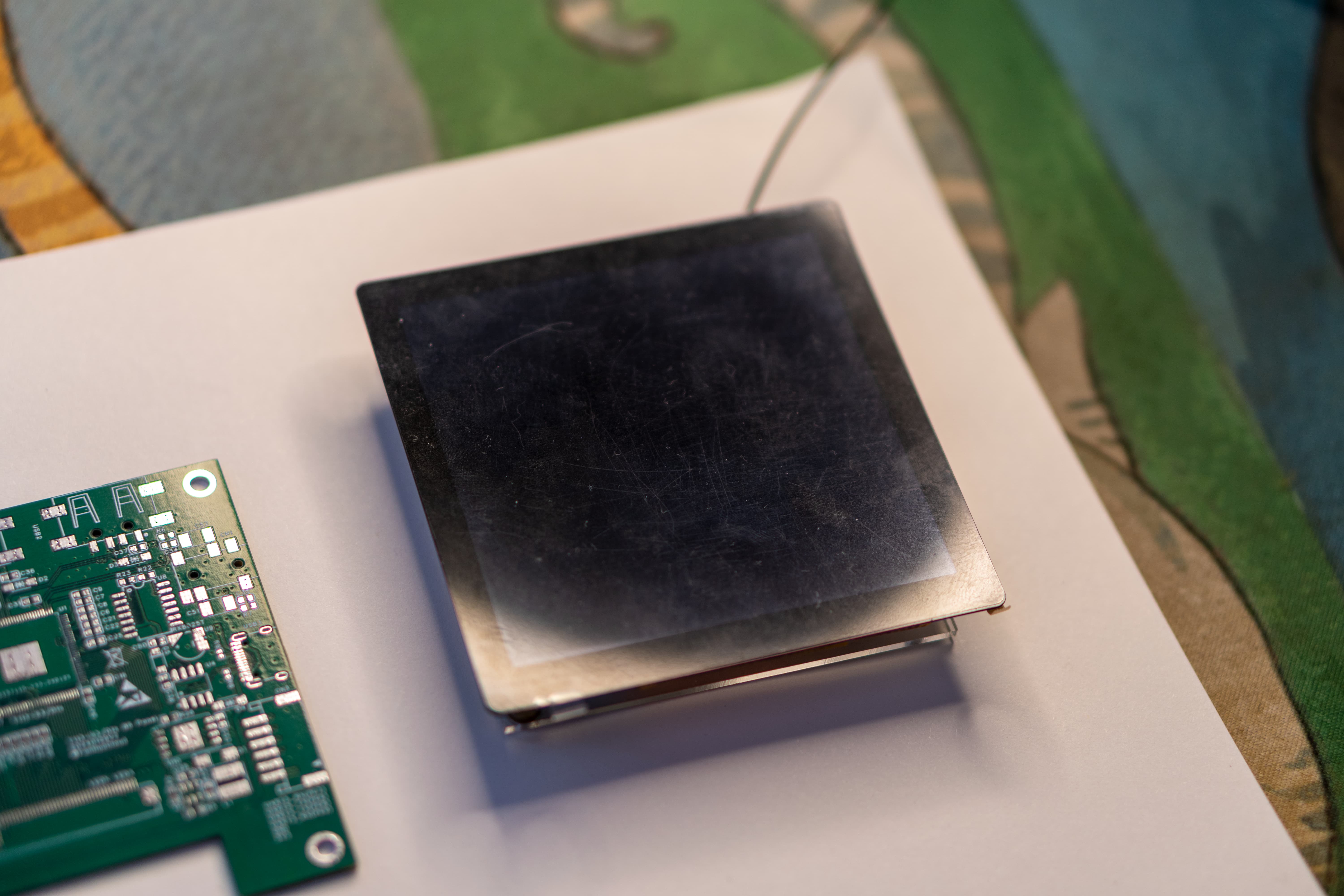
This project is an 86-type smart touchscreen solution for smart home scenarios, based on the Allwinner T113-S3 chip. The Allwinner T113-S3 chip integrates advanced processor technology and is designed to meet the performance, power consumption, and wireless connectivity requirements of smart home control systems.
Project Features:
4-inch 86-inch screen, RGB interface, 480*480 resolution;
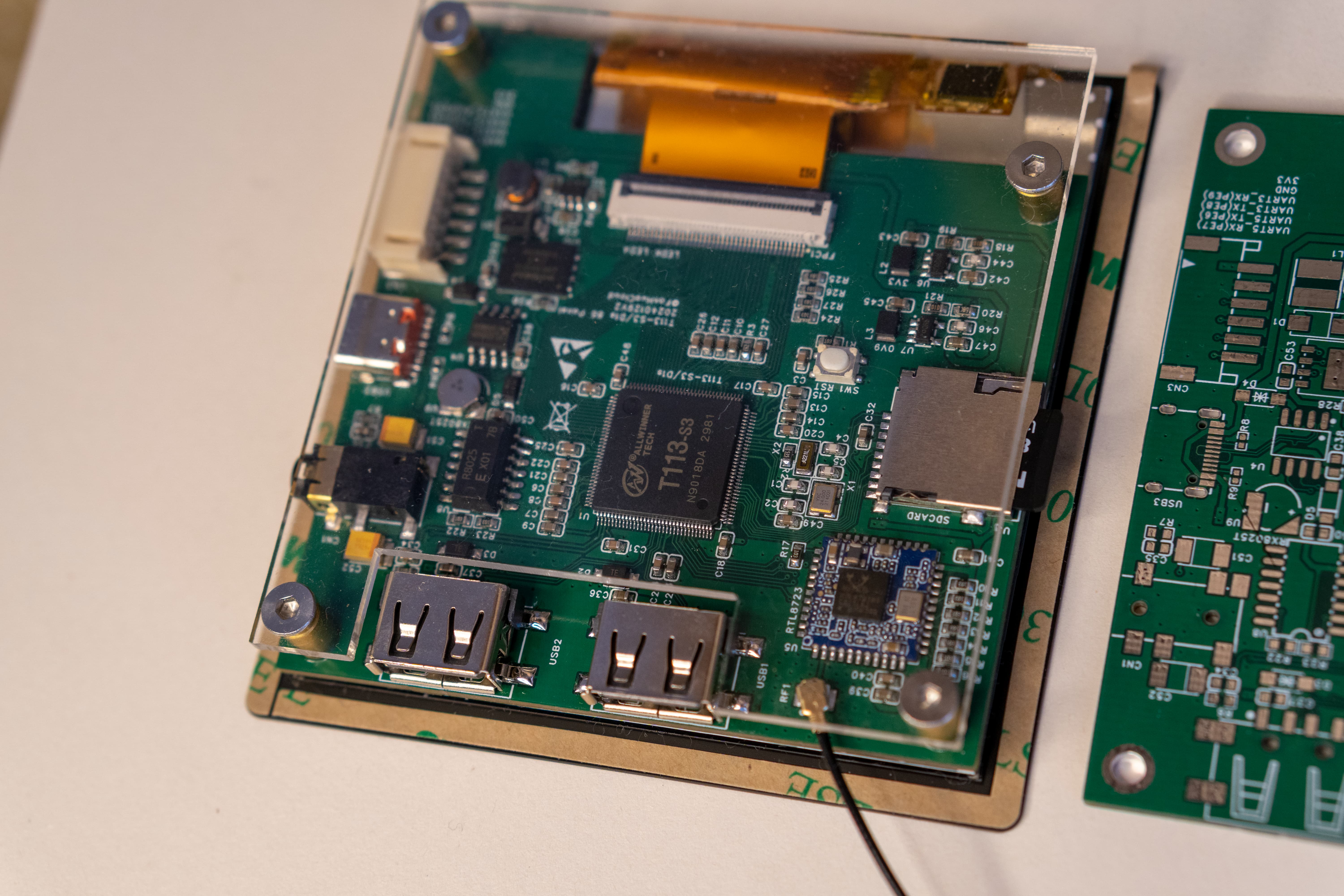
Allwinner T113-S3 main controller, dual-core A7, 128MB memory, supports hardware decoding and D1s Pin-to-Pin, supports interchangeable
RTL8723 WIFI modules for connecting WIFI
SPI Nand, supports booting the system from SPI Nand;
dual USB interfaces, one supports Host/Device, the other only supports
two serial ports extended by PH2.0 for RS485 and other functions;
adapts to Allwinner Tina-Linux, supports fast boot;
Hardware
Cost: PCB board 58 RMB + screen 69 RMB, approximately 127 RMB;
Main controller chip: T113-S3 (can be replaced by D1s)
; WIFI module: RTL8723BS (planned to be replaced by RTL8723DS);
RTC chip: RX8025T-UB/UC (driver has some issues, Tina-Linux is not currently supported);
Serial to USB: CH340N
SPI NAND: W25N01G (not yet tested)
Backlight Driver: RY3730
chip Power Supply: SY8089AAAC
Screen: ST7701 86-inch screen with RGB interface, 480x480
Hardware Design Reference:
[Allwinner Online x YuzukiHD] Nezha D1s Development board
: https://oshwhub.com/GloomyGhost/34e1fe88b79f49b891df150db9c34cc4
Reference purchase links
: T113-S3: https://item.taobao.com/item.htm?_u=d2dklb454adf&id=688651947152&spm=a1z09.2.0.0.59e42e8d2pGc20
Screen, select (Display + Touchscreen): https://item.taobao.com/item.htm?_u=d2dklb4513ca&id=651209491676&spm=a1z09.2.0.0.59e42e8d2pGc20
Headphone jack, select (PJ-342) Gold-plated 3.5mm headphone jacks (5 jacks): https://detail.tmall.com/item.htm?_u=d2dklb455626&id=14476732895&spm=a1z09.2.0.0.59e42e8d2pGc20
USB connector, select (four-pin surface mount (black glue/with edge)): https://item.taobao.com/item.htm?_u=d2dklb4573d8&id=674663700649&spm=a1z09.2.0.0.59e42e8d2pGc20
Solder copper pillars, select (M3*6.5*5 [10 pieces] copper): https://detail.tmall.com/item.htm?id=651557523848&spm=a1z09.2.0.0.59e42e8d2pGc20&_u=d2dklb45808d
SD card slot, Type-C connector: Refer to LCSC Mall for purchase
W25N01G: Choose a suitable one on Taobao.
Mass production precautions
RTC
There are currently software compatibility issues with the RX8025T. For hand soldering, use the built-in RTC
soldering tool on the T113-S3
to solder the copper pillars. Apply solder paste around the screw holes, then heat with a hot air gun or heating pad. For
the acrylic backplate
, select "Backplate" PCB, export only the mechanical layers, and send it to Taobao for cutting. For
firmware testing , use
an SD card. For the RTL8723BS Wi-Fi: please refer to the attached tina_t113-86_uart0.img
firmware. To burn the firmware
, insert the SD card into your computer, open PhoenixCard.exe, click "Firmware," load the img firmware, select the boot card, and then click "Burn Card." Note that you must select the boot card; otherwise, the boot process will fail!

SDK development
reference: Refer to the documentation below
for assembly.
Use M3*5 screws (hex socket screws are recommended as they are less prone to stripping). Simply screw on the acrylic backplate.
Use double-sided tape for the screen; 3M 4229P double-sided tape (5mm wide) is recommended.
Hardware
video decoding: https://www.bilibili.com/video/BV1VH4y1E7rD/
Music playback: https://www.bilibili.com/video/BV1ep421o7GT/
LVGL: https://www.bilibili.com/video/BV1Kt421p7jq/?vd_source=be70fa55ac113f4735a6b71fc42e5574
Bilibili demo video:
https://www.bilibili.com/video/BV1VH4y1E7rD/?vd_source=be70fa55ac113f4735a6b71fc42e5574
[Links to videos on Bilibili: https://www.bilibili.com/video/BV1ep421o7GT/
, https://www.bilibili.com/video/BV1Kt421p7jq/
, https://www.bilibili.com/video/BV1Vu4m1K7pX/?vd_source=be70fa55ac113f4735a6b71fc42e5574
, https://www.bilibili.com/video/BV1iU421d7KB/?vd_source=be70fa55ac113f4735a6b71fc42e5574
, https://www.bilibili.com/video/BV1Ja4y187B5/?vd_source=be70fa55ac113f4735a6b71fc42e5574] [ Links to videos
on Bilibili and Tina SDK are provided.] Configure the WSL environment according to the requirements. For detailed instructions, please refer to Baidu. Ubuntu 20 is recommended. After installing the build tools and entering the system, enter the following commands to install the required tools: `sudo apt update -y` `sudo apt full-upgrade -y` ` sudo apt install -y` `ack antlr3 asciidoc autoconf automake autopoint binutils bison build-essential bzip2 ccache cmake cpio curl device-tree-compiler fastjar flex gawk gettext gcc-multilib g++-multilib git gperf haveged help2man intltool libc6-dev-i386 libelf-dev libfuse-dev libglib2.0-dev libgmp3- dev libltdl-dev libmpc-dev libmpfr-dev libncurses5-dev libncursesw5-dev libpython3-dev libreadline-dev libssl-dev libtool lrzsz mkisofs msmtp ninja-build p7zip p7zip-full patch pkgconf python2.7 python3` The following tools are used to install the Repo tool: python3-pyelftools, python3-setuptools, qemu-utils, rsync, scons, squashfs-tools, subversion, swig, texinfo, uglifyjs, upx-ucl, unzip, vim, wget, xmlto, xxd, and zlib1g-dev. Repo is a tool developed by Google for managing Android repositories. It's a Python wrapper around Git, not a replacement for Git, but it simplifies the management of multiple Git repositories. Repositories managed by repo require Git commands for operation. Therefore, ensure Git is installed before using repo. Why use repo? After project modularization/componentization, each module is separated from the main project as an independent Git repository, managing its own version. Android source code references many open-source projects, each sub-project being a Git repository with many branches. To facilitate unified management of these sub-projects' Git repositories, a higher-level tool is needed for batch processing, hence the creation of repo. The repository also creates a Git repository to record which branch each sub-project's Git repository belongs to under the current Android version. This repository is usually called the manifest repository. Please refer to the attached Tina SDK Build Guide.pdf (uploading code to the webpage will trigger keywords, please be sure to read the attached document!!!) https://oshwhub.com/attachments/2024/2/MrgsWEOpeveQ1DKC61X53E7aN7jAzjTNlf2S2IN5.pdf?operation=download Tina-SDK Development Documentation (These are development documents written by Allwinner itself. The documents are too large, so they can only be shared via Baidu Cloud) Link: https://pan.baidu.com/s/1D8aXmBYUHejMhualUpo79Q?pwd=7ckw Extraction code: 7ckw Copy this content and open the Baidu Cloud mobile app for easier operation. Showing images


base-files.tar.gz
phoenixcard4.2.8.zip
t113-s3_datasheet_v1.2.pdf
D1_SCHEMATIC_NEZA_V1_2.pdf
t113-s3_user_manual_v1.1.pdf
ST7701_v1.2.pdf
board.dts
config-5.4
defconfig
env.cfg
st7701_86.c
st7701_86.h
sys_config.fex
sys_partition.fex
Tina SDK Build Guide.pdf
tina_t113-pi_uart0_sdcard.img
tina_t113-pi_uart0_spinand.img
t113_linux_pi_uart0_480.img
PDF_Allwinner T113-S3 Smart Home 86-Screen.zip
Altium_Allwinner T113-S3 Smart Home 86-Screen.zip
PADS_Allwinner T113-S3 Smart Home 86-Screen.zip
BOM_Allwinner T113-S3 Smart Home 86-Screen.xlsx
90875
Purple Gold Gourd (humidifier), if I call your name, will you dare to answer?
Humidifier (Purple Gold Treasure Gourd)
Project physical image:

Project video display: https://www.bilibili.com/video/BV1jrgLe4Ef5/
Project origin:
After turning on the air conditioner in summer, the air is too dry, so a humidifier can be used. (Mainly to participate in the event to get free coupons)
Project core functions:
1. A gourd-shaped humidifier.
(1) Opening the lid turns it on, and closing the lid turns it off.
(2) There is a small tail on the gourd lid. Rotating the small tail can adjust the size of the mist. There is also an air outlet at the mist outlet, which can blow the water mist higher. The size of the air blow is adjusted synchronously with the size of the mist.
(3) To indicate how much water is left in the gourd, there is a breathing light on the belly of the gourd. When the water level is greater than 20%, the blue breathing light will flash. When the water level is less than 20%, the red light will start to flash to remind you that water needs to be added.
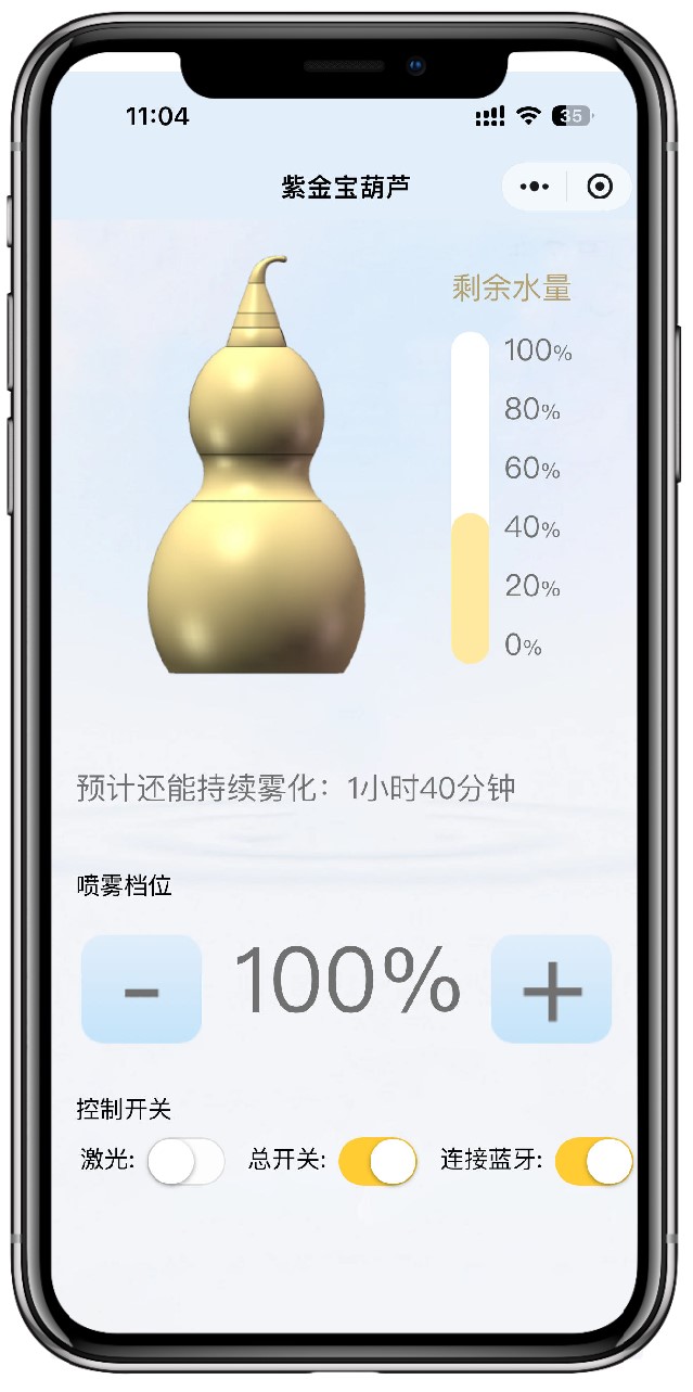
(4) A WeChat mini program was also developed, which uses Bluetooth connection. You can clearly see the remaining water in the gourd on your mobile phone. You can also remotely control the size of the atomization, the laser switch (for entertainment purposes), and the overall power on/off of the device.
2. Entertainment function (Imitate "If I call your name, will you answer?")
(1) You can turn on the gourd laser on the mini program. A laser beam will shoot out from the bottle mouth. Aim at someone you can joke with (note: do not shoot into their eyes) and shout "XXX, if I call your name, will you answer?"
Technical implementation:
1. Structural part (as shown in the figure below)
(1) The gourd can be placed anywhere. Even if it falls over, there is no fear of water flowing out because a one-way water valve is used at the inlet.
(2) The atomization path is connected to the atomization chamber through the U-shaped pipe below. A sponge rod is also placed to make the atomization more uniform.
(3) The small tail can adjust the atomization size because a rotary potentiometer is added to the cap.
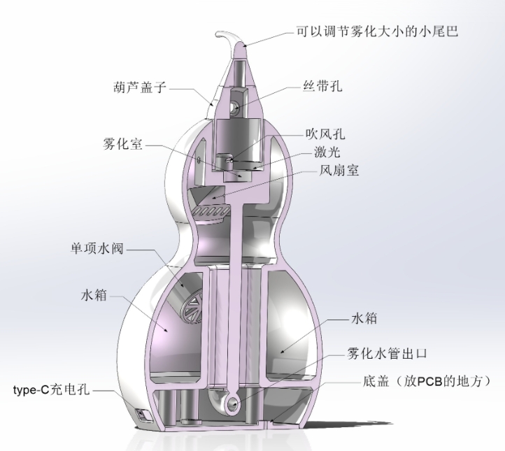
2. Hardware: See schematic diagram
(1). Two boards are used: one main board and one board for water level detection (which needs to be attached to the water tank).
(2) The main control chip uses ESP32-C3, which has built-in WIFI and BLE, thus facilitating Bluetooth communication.
(3) The power supply supports Type-C and lithium battery power supply. It has a built-in 1800mA lithium battery, and Type-C can charge the lithium battery.
(4) The laser and fan are driven by MOSFETs.
(5) Three 2812B LEDs are used for light indication.
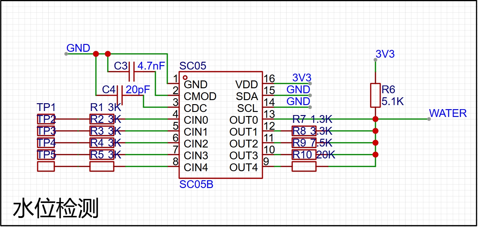
(6) A 5-channel SC05B touch chip is used for water level detection, which achieves the finest water level detection of 20%.
(7) Opening the cover turns on the machine, and closing the cover turns it off. A layer of copper foil is attached to the cover and a layer of copper foil is also attached to the inside of the contact port. Thus, when the cover is closed, the copper foil connects with the copper foil to realize the function of turning on and off the machine.
3. Software (Embedded software + WeChat mini-program) See open source materials for details.
(1) RTOS multitasking is used to control different modules.
(2) PWM wave is used to adjust the size of the atomization. Of course, a 25:800 surface mount inductor is used to excite the atomizing plate in the hardware.
(3) ADC is used to detect the analog signals of the rotating potentiometer and water level detection. The water level detection is achieved by different resistors to detect different water levels (as shown in the figure below).
(4) The WeChat mini-program is relatively simple because it is only one page. However, the UI is not very beautiful. My art skills can only do this much (the WeChat mini-program is shown in the figure below). Note: Because the WeChat mini-program needs to be registered, it cannot be opened for the time being. It can only be opened to the public after the registration is approved. (Wait a moment)
Software open source address (including structure and material list): https://github.com/Jgcoder2023/oscilloscope
Project video demonstration: https://www.bilibili.com/video/BV1jrgLe4Ef5/
PDF_Purple Gold Gourd (Humidifier), If I call your name, will you dare to answer? .zip
Altium_Purple Gold Gourd (Humidifier), if I call your name, will you dare to answer? .zip
PADS_Purple Gold Gourd (Humidifier), if I call your name, will you dare to answer? .zip
BOM_Purple Gold Gourd (Humidifier), if I call your name, will you dare to answer? .xlsx
90876
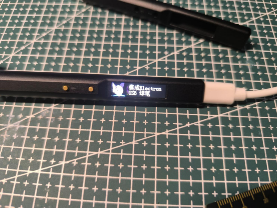
JBC-C210-USB Temperature-Controlled Solder Pen
This ultra-compact CNC temperature-controlled soldering pen uses a JBC-C210 soldering iron tip, is 5V-2A, has a maximum power of 10W, automatic temperature control, power control, a full-color digital display, and an ultra-small size.
Preface: A long time ago, when I first used a soldering iron, I wondered why soldering irons are so long now. Soldering already makes my hand tremble a bit, and being so long makes it even worse. Plus, they're bulky and inconvenient to carry, and they heat up slowly. So I wanted to make my own small and convenient soldering iron.
This is an ultra-small digital display temperature-controlled soldering pen, melting solder in 3 seconds, with automatic temperature control, a full-color digital display, and an ultra-small size. It's even slightly smaller than a regular ballpoint pen.

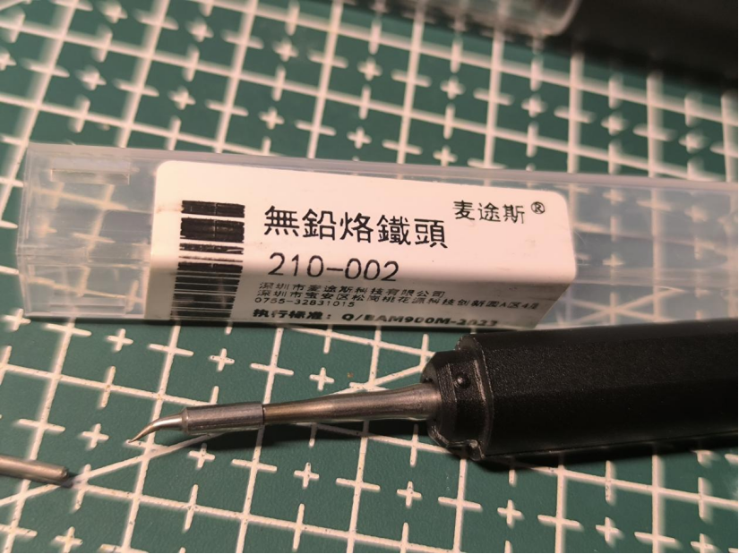
The recommended soldering iron tip is the imported JBC-C210. The domestic C210 tip can also be used.
Basic parameters:
Power supply: Type-C (5V-2A)
Power: 10W
Temperature rise rate: 3~4S (5V-2A 300℃)
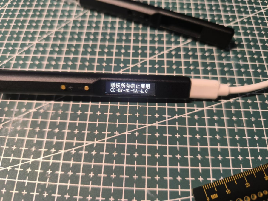
Open source license: CC-BY-NC-SA-4.0 (Commercial use is strictly prohibited; infringement will be prosecuted)
Workflow diagram:
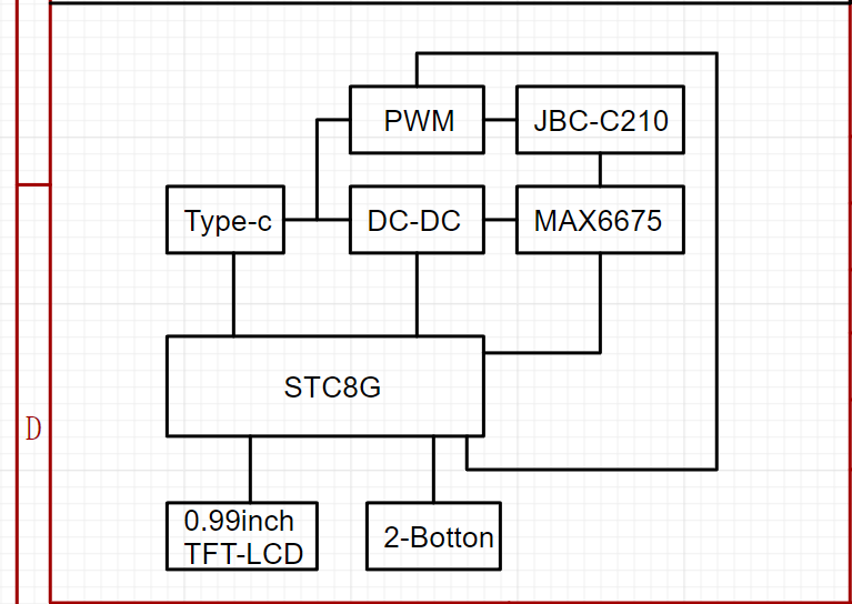
Main controller selected: STC8H8K64U-QFN32 (Program runs at IRC frequency 11.0592MHz)

To minimize circuit board size and space, a QFN-32 package was chosen.
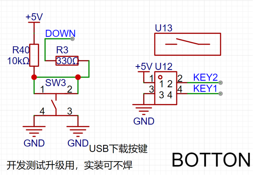
Development notes: Initially, the plan was to use the STC32G12K128 model, programmed with a C251 microcontroller. However, testing revealed limitations in writing TFT refresh programs with the C251 (compatibility errors). Therefore, an STC8H was downgraded. Initially, the pin configuration wasn't carefully considered. When downgrading from STC32G to STC8H, special attention must be paid to the P1.2 pin. This pin is different between the two chips, and in the STC8H-QFN32 package, this pin cannot be set as an output in the program; setting it as an output will prevent the chip from powering on. For ease of debugging, the program downloads via USB, communicating directly with the computer through P3.2 to enter USB download mode (onboard download button).
The temperature controller uses the MAX6675 (also to save space and eliminate the need for analog peripheral circuitry, but at the cost of a slower temperature sampling speed).

In the JBC-C210 soldering iron tip, because the heating wire and thermocouple are connected in series, the heating wire must be energized during heating. To prevent high voltage backflow into the MAX6675 thermocouple sensing pin, which could burn out the MAX6675, a buffer clamping circuit needs to be added to the T+ signal line to limit the maximum voltage of this pin (all pins of the MAX6675 can withstand 3.3V). The program must stagger the heating and temperature measurement periods! Additionally, the MAX6675 temperature conversion process requires approximately 200ms of conversion time (this requires ensuring that each temperature data conversion in the program lasts at least 200ms, otherwise no data will be generated).
The microcontroller queries the MAX6675 for the temperature, but before the MAX6675 finishes calculating, the microcontroller queries again, and the MAX6675 recalculates. Initially, this was the reason why no data was generated.

Procedure: Heat for a period of time, then disconnect the power and wait for discharge. Measure the temperature to determine if heating needs to continue. If yes: continue heating; otherwise: stop heating.
The heating time also serves as the conversion time for the MAX6675 to the previous temperature data, improving program efficiency.
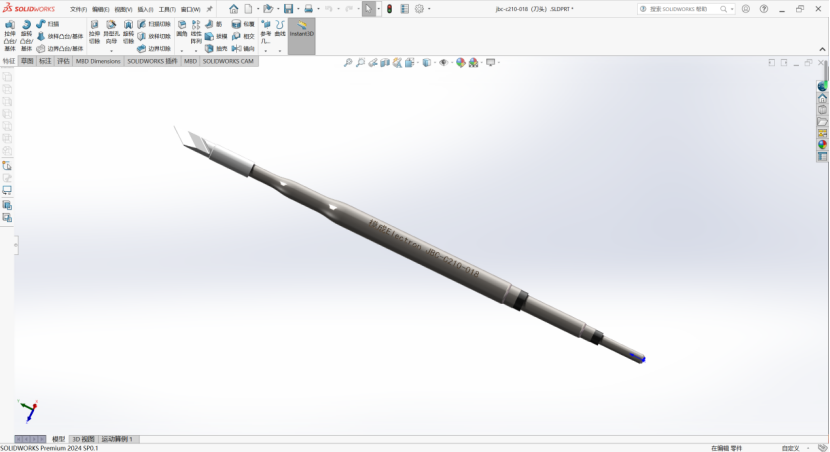
Regarding the soldering iron heating element:
I couldn't find any information about the JBC-C210 online, not a single piece of information. Later, I accidentally discovered that there were domestically made C210 soldering iron elements,
but still no information. So I bought two heating elements online and measured the pin definitions. I then created a 3D model of the soldering iron element based on the actual product for assembly and design simulation (modeling file attached).
After three board modifications, I measured the pin definitions (I'm not sure if they're correct; if anyone has information, please reply in the comments).

Regarding the screen:
The screen is a 0.99-inch SPI interface TFT-LCD screen (control chip GC9D01) with a resolution of 40*160 RGB full color.
Note: The area with the number 6 in the middle is a dead pixel on the screen, unrelated to the program display. (I was quite unlucky; I bought two screens for testing, one screen's ribbon cable broke due to excessive bending, and the other screen had a dead pixel upon power-on.) The new one hasn't arrived yet, so I can only use the one with the dead pixel for testing.
When purchasing the screen, choose the plug-in model. When plugging it in, the gold fingers of the ribbon

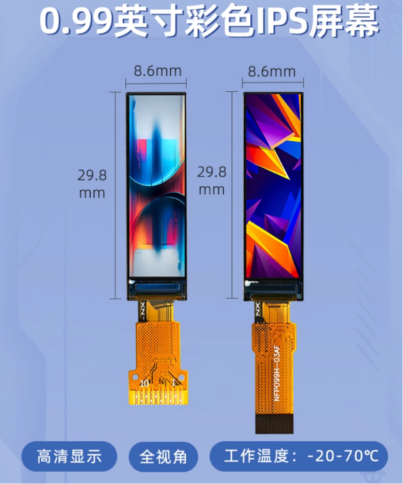
cable should face upwards. The circuitry is straightforward; it's ready to use immediately after plugging in. (I've retained the backlight circuitry for future program upgrades to include sleep mode.)
Screen link:
https://item.taobao.com/item.htm?spm=a1z09.2.0.0.13462e8diktIQE&id=677743417274&_u=h20292vc2r95f1&skuId=5076130632004
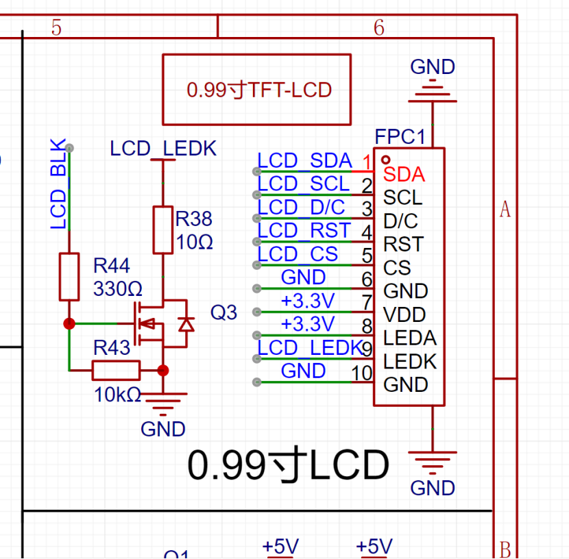
The value of resistor R38 affects the maximum backlight brightness; the minimum value should not be lower than 10Ω, as a lower value may cause burnout.
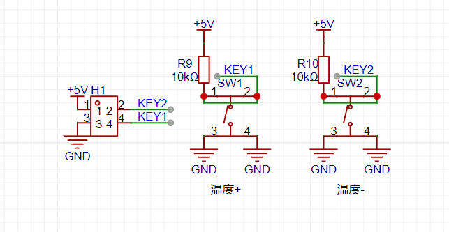
Regarding the buttons:
Please pay special attention here: LCSC serial number: C318886 (Only this model has the correct button height; many other models I bought before didn't have the right height.)

The download button (SW3) doesn't need soldering.
Regarding the PCB:
Initially, the first version was designed as a 4-layer board due to current carrying capacity considerations and the desire to implement power detection and fast charging. However, the actual cost was quite high, and the measured voltage drop across the traces was significant (we later considered thickening the traces and changing the design). The second version removed unnecessary functions and optimized the circuitry and traces, successfully converting it to a 2-layer board. When prototyping the PCB, ensure the board thickness is 0.8mm; otherwise, the casing won't fit.


Regarding the casing:
The casing itself
is made of aluminum alloy and requires CNC machining. 3D printing is not possible here, as the heating element of the soldering iron will melt the 3D printed parts during operation!
Shell Machining: The shell is machined by JLCPCB
using CNC machining parameters: aluminum alloy - 6061 GB/T 1804-2000 m grade Ra3.2.
Surface treatment is: ordinary anodizing - black - matte (this is not a necessary parameter and can be customized).

Solidworks Modeling


Pen Cap Machining:
I used JLCPCB SLA resin to print the pen cap, but in actual testing, the resin structure strength was insufficient. If it is a version with a hook, the hook itself is relatively fragile. However, 3D printing is low-cost, so
it is recommended to use a high-temperature resistant and transparent material.
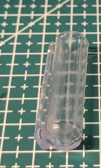

When using the pen cap, it can also be used as a simple soldering iron stand.
Overall assembly simulation diagram:

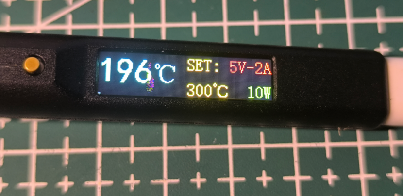
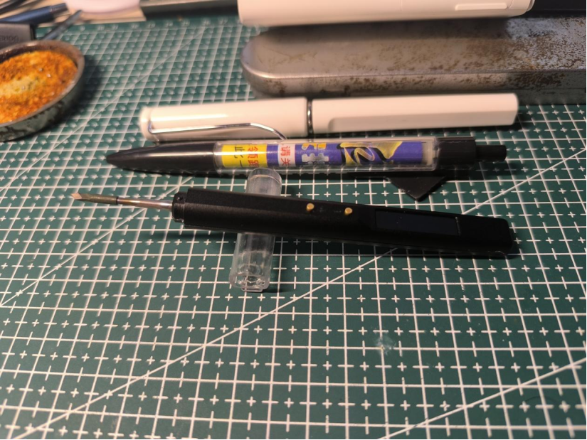
Actual product image:


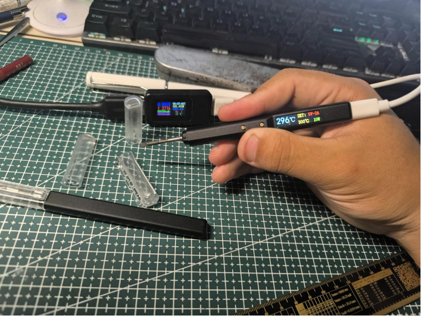

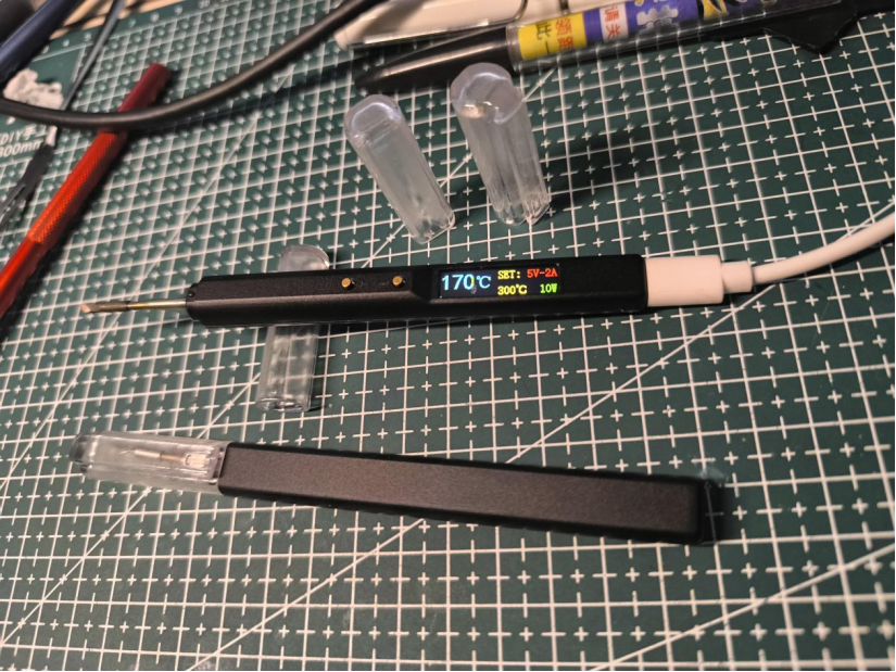


Interaction:
The initial default temperature after power-on is 300 degrees Celsius (the default temperature can be changed in the program, but it is not recommended to exceed 400 degrees Celsius).
Pressing the + button once increases the temperature by 10 degrees Celsius; pressing the - button once decreases the temperature by 10 degrees Celsius.
Future upgrades and improvements:
1. Add PD and QC fast charging protocol support without increasing the size
. 2. Increase the maximum power from 10W to 100W.
3. Optimize the UI interaction interface and add real-time power change display.
4. Stay tuned.
Test video: https://www.bilibili.com/video/BV1MZ421M7Tr/?spm_id_from=333.999.0.0&vd_source=f2ecf6d07c56387a85d94b5338693a63
The 3D shell and program files are attached.
Data package.zip
Bareboard Debugging.mp4
Temperature Adjustment.mp4
PDF_JBC-C210-USB Temperature-Controlled Solder Pen.zip
Altium_JBC-C210-USB Temperature-Controlled Solder Pen.zip
PADS_JBC-C210-USB Temperature-Controlled Solder Pen.zip
BOM_JBC-C210-USB Temperature-Controlled Solder Pen.xlsx
90877
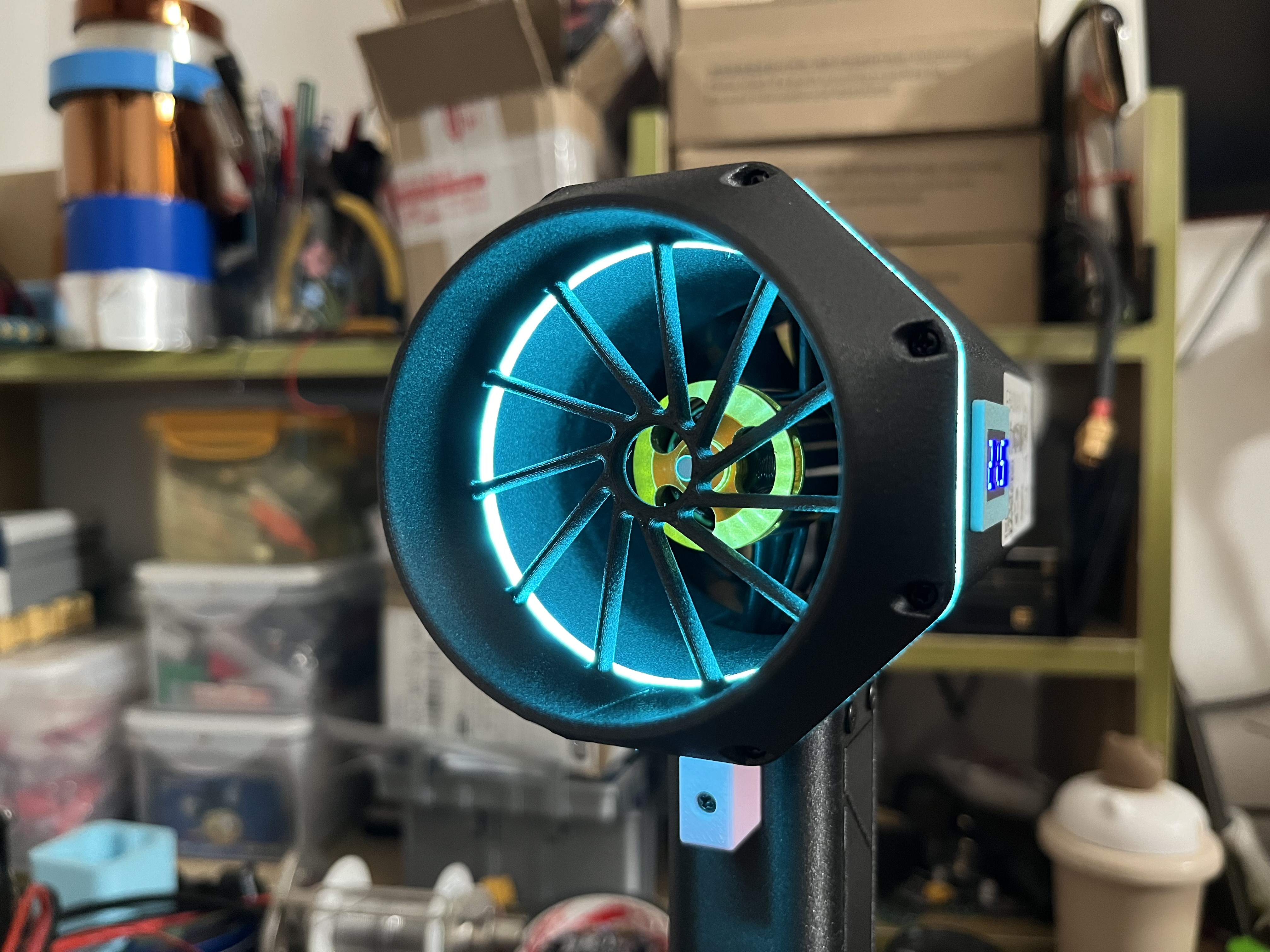
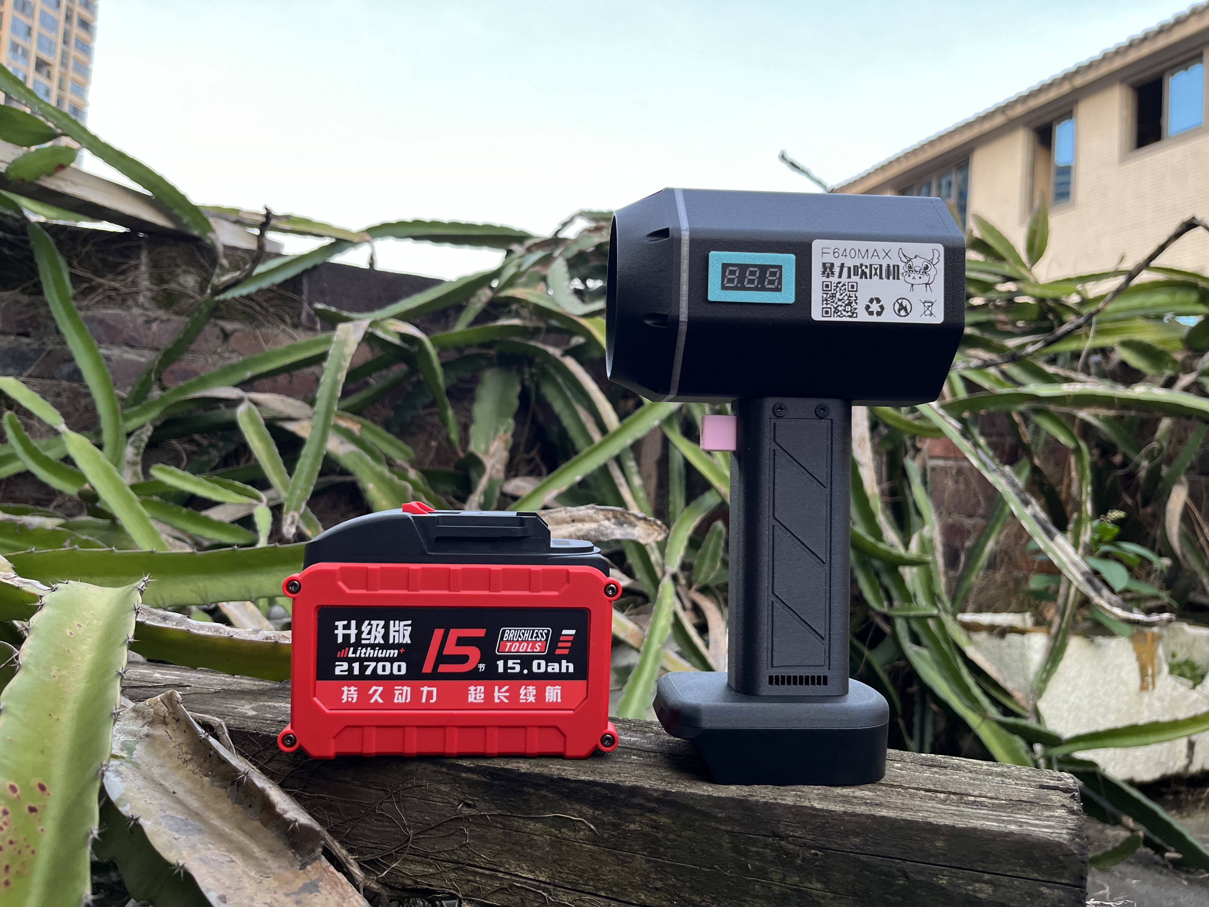
Handheld Power Hair Dryer MAX
Handheld Power Hair Dryer Upgrade
======WARNING======
The BOM (Bill of Materials) should be based on the schematic diagram! Do not use the BOM in the project description directly!
Please follow the CC-BY-NC-SA 3.0 open-source license. This project is for learning and research purposes only and is prohibited for commercial use.
Electronics exchange groups: 232586710, 345731137 Friendly reminder: Please see the materials list in the attachment area for purchasing some materials.
It has been more than four months since the last version was released,
so this time we're giving it a small upgrade.
The overall structure inherits the design language of the previous generation,
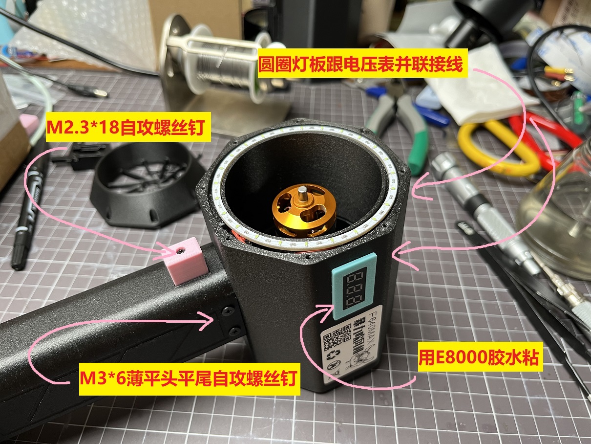
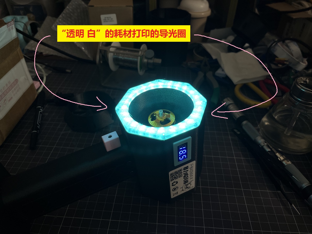
with a ring of ice-blue ambient light .
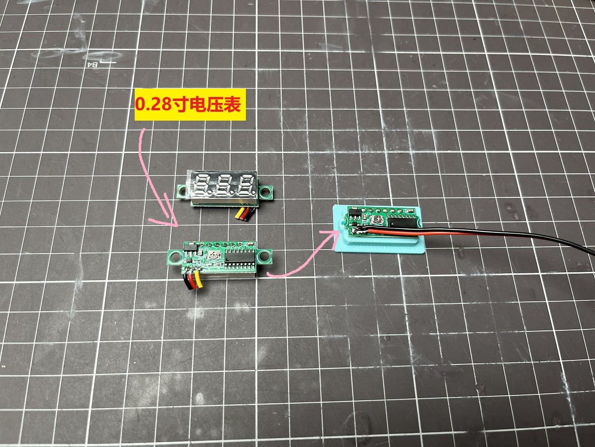
On the side is a voltmeter for displaying battery power.
This time, we're using a removable and replaceable power tool battery .
These power tool batteries are easy to buy, eliminating
the hassle of spot welding batteries
and greatly reducing the difficulty of manufacturing.
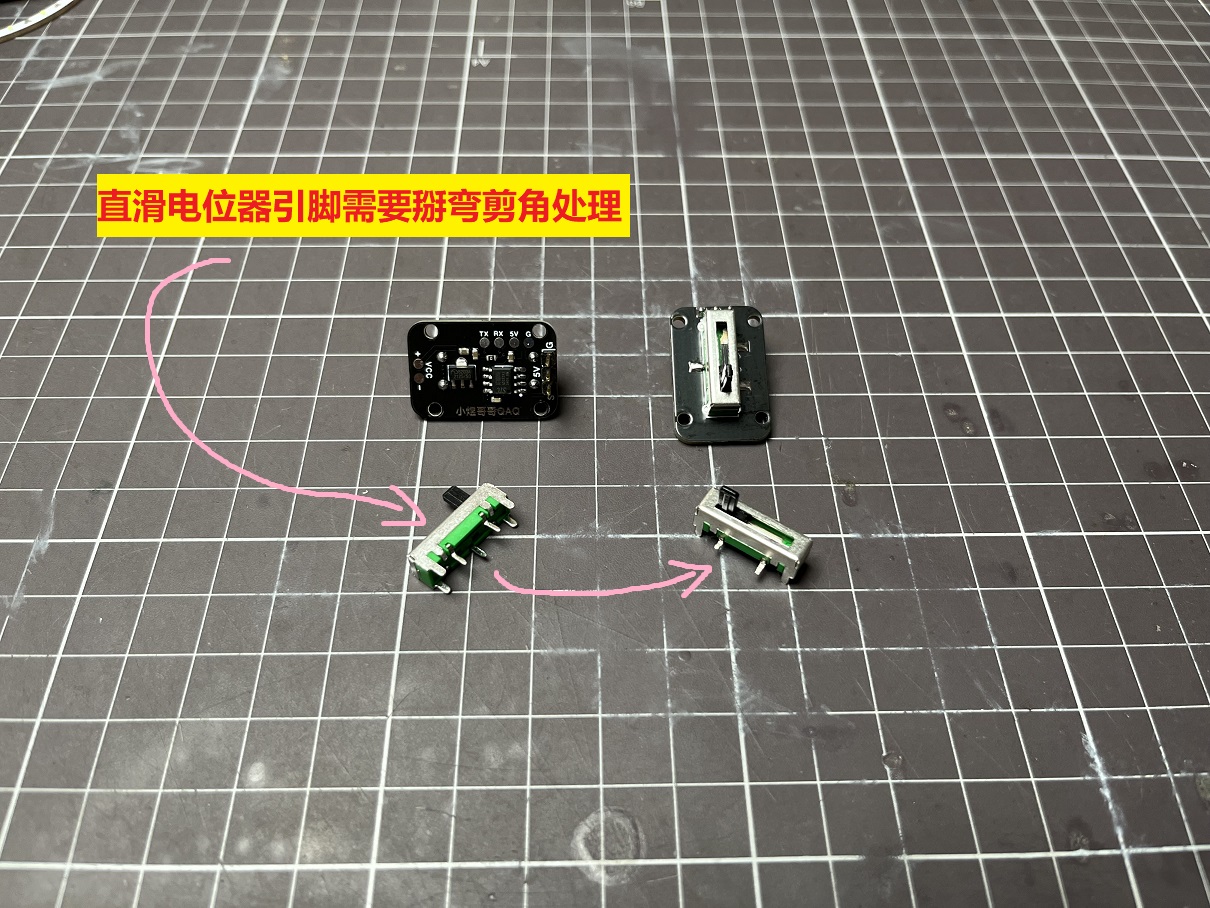
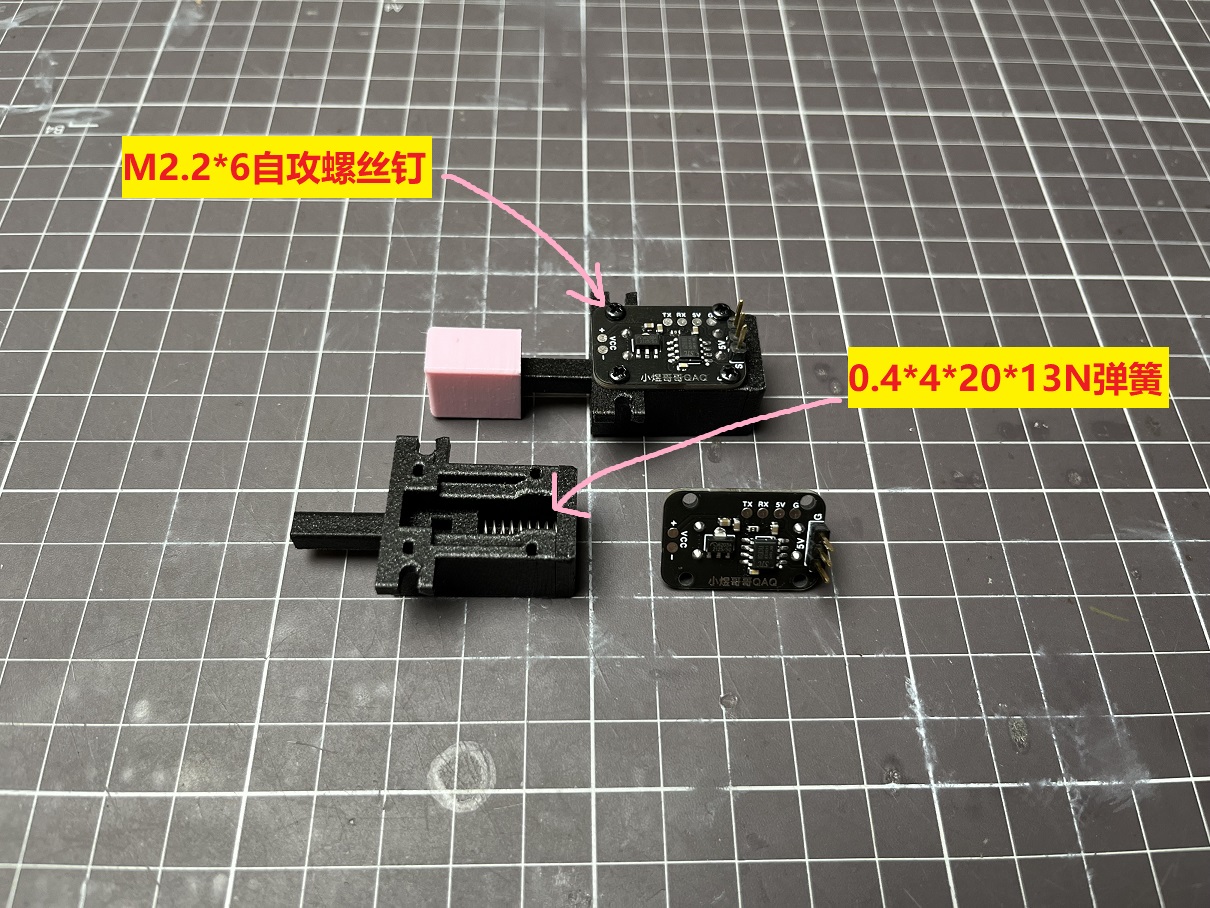
The speed control mechanism uses a linear potentiometer with spring reset,
achieving a press-to-adjust speed control mechanism like a power drill.
————————————————
Update Log:
June 17, 2024:
Shell Model File Update
1. Added air guide wall at the duct outlet to allow more airflow to reach the handle, enhancing ESC heat dissipation.
2. Widened the lower air outlet of the handle to allow more airflow out, enhancing ESC heat dissipation.
3. Added support for Worx large-foot power strip.
Appearance Appreciation

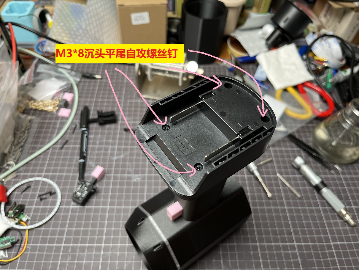
Installation Instructions
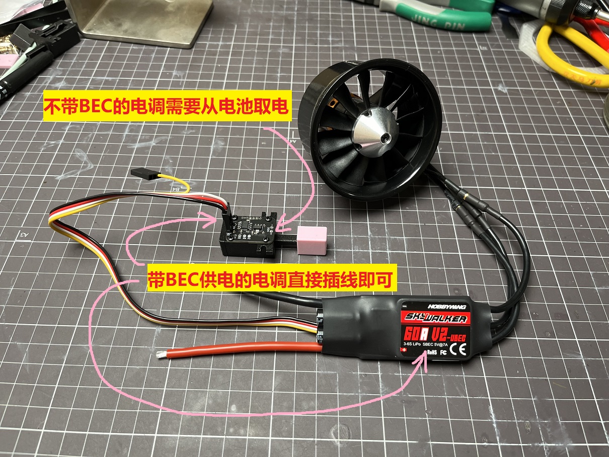
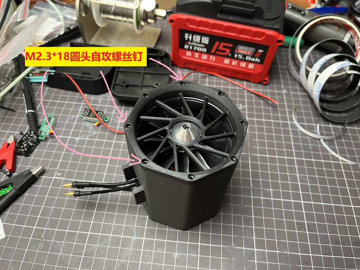
The duct fan used is a Qunxi 2400KV 64-duct. A 60A Hobbywing Skywalker ESC is recommended.
Note that the original banana head connector of the ESC is 4.0mm and needs to be replaced with a 3.5mm
0.28-inch voltmeter. The fixing feet need to be cut off and glued to the mounting frame.


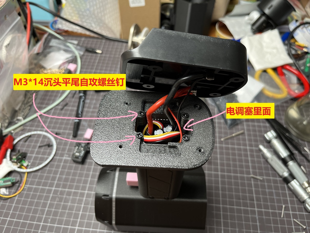
A "Makita" battery power strip is used here; you can replace it with the appropriate power strip depending on the power tool battery you have.
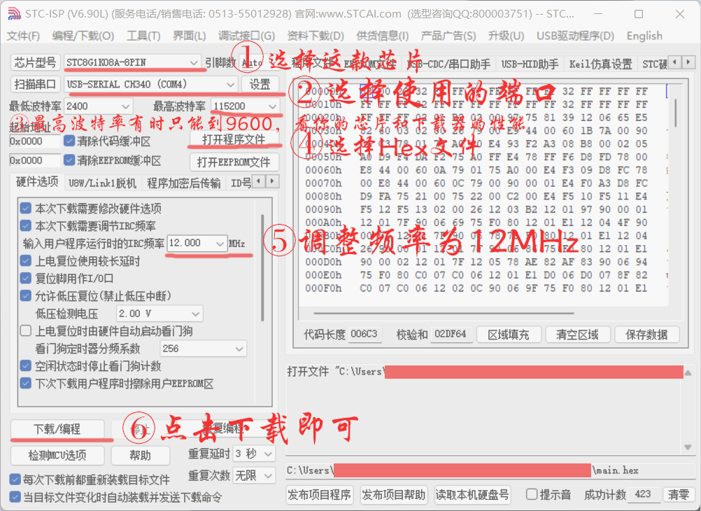
Speed Switch Programming Precautions
Materials Purchase List.rar
Press-to-operate speed switch housing.rar
program.rar
Demonstration 1.MP4
Demonstration 2.MP4
F640 Hair Dryer Case - New.rar
PDF_Handheld Violent Hair Dryer MAX.zip
Altium_Handheld High-Power Hair Dryer MAX.zip
PADS_Handheld High-Power Hair Dryer MAX.zip
BOM_Handheld High-Speed Hair Dryer MAX.xlsx
90878
electronic


 京公网安备 11010802033920号

 15KP150CA-AP


