Project Overview:
This project utilizes Espressif Systems' ESP32-S3-WROOM-1 module as the system's main controller, leveraging its LEDC and MCPWM modules to drive the three-phase inverter circuit. Furthermore, the system supports integration with RainMaker for brushless motor start/stop and speed control. Based on the control principles of this solution, interesting applications such as intelligent sensorless fans can be implemented.
Supported Features:
12V voltage input
; USB and serial port
programming support; sensorless start
support; motor speed regulation
support; LEDC and MCPWM support.
Development Guide:
Development Environment
: ESP-IDF: Espressif Systems open-source software framework.
Three-Phase Inverter Circuit Driver:
This solution uses the EG2133 chip as the three-phase inverter circuit driver, internally integrating logic signal input processing circuits, dead-time control circuits, latching circuits, level shifting circuits, pulse filtering circuits, and output drive circuits.
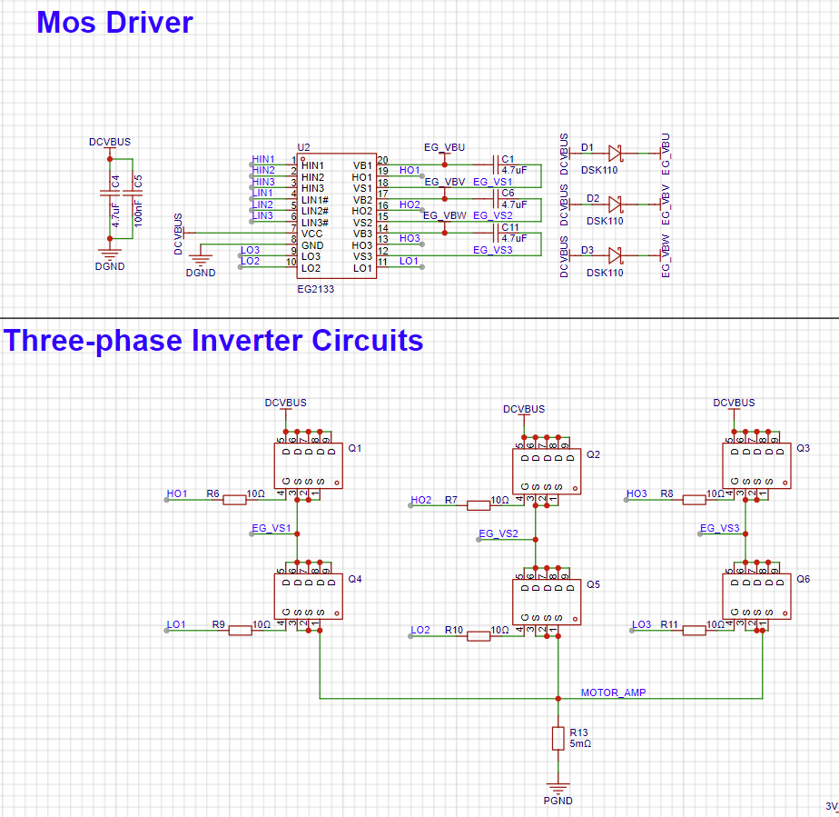
ADC Detection Principle :
The three-phase terminal voltages of the brushless motor are directly acquired through a voltage sampling circuit, and the zero-crossing point of the floating back EMF is calculated using software calculation methods. Additionally, the ADC detection method requires acquiring the bus voltage in each control cycle to determine the theoretical neutral point voltage, and comparing it with the terminal voltage of the floating phase to obtain the zero-crossing point of the back EMF.

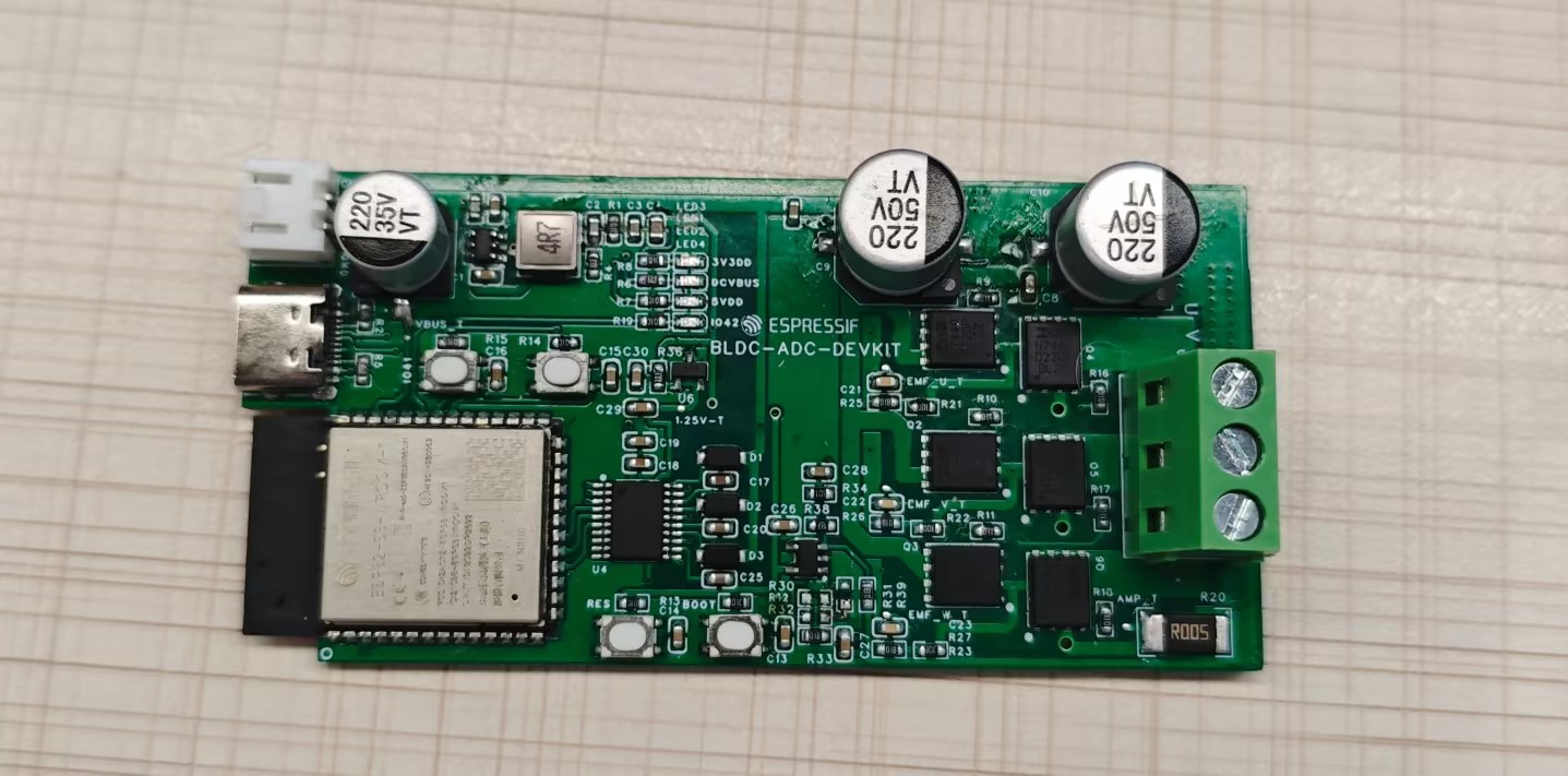
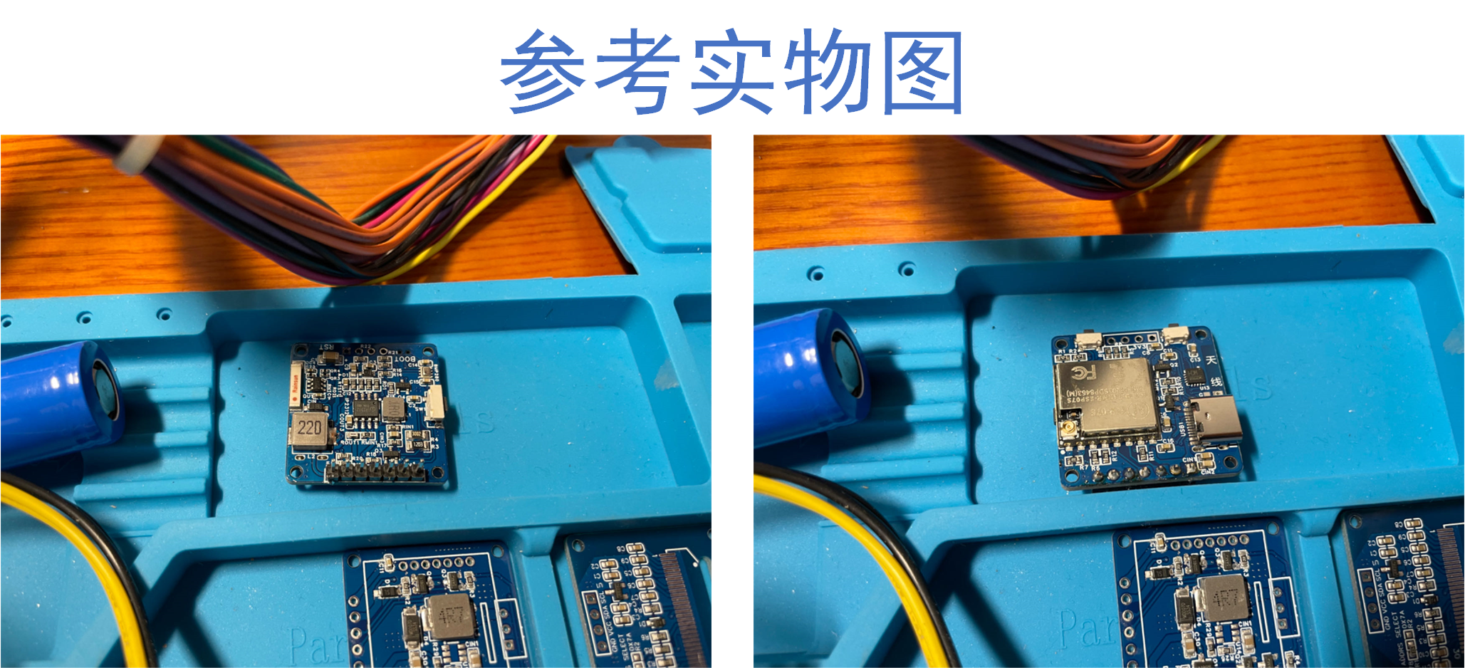
Hardware Design
and Physical Diagram:
Open Source Code:
esp_sensorless_bldc_control: BLDC brushless motor driver library.
Supports ADC-based zero-crossing detection,
comparator-based zero-
crossing detection, pulse-based rotor initial phase detection,
and stall protection.
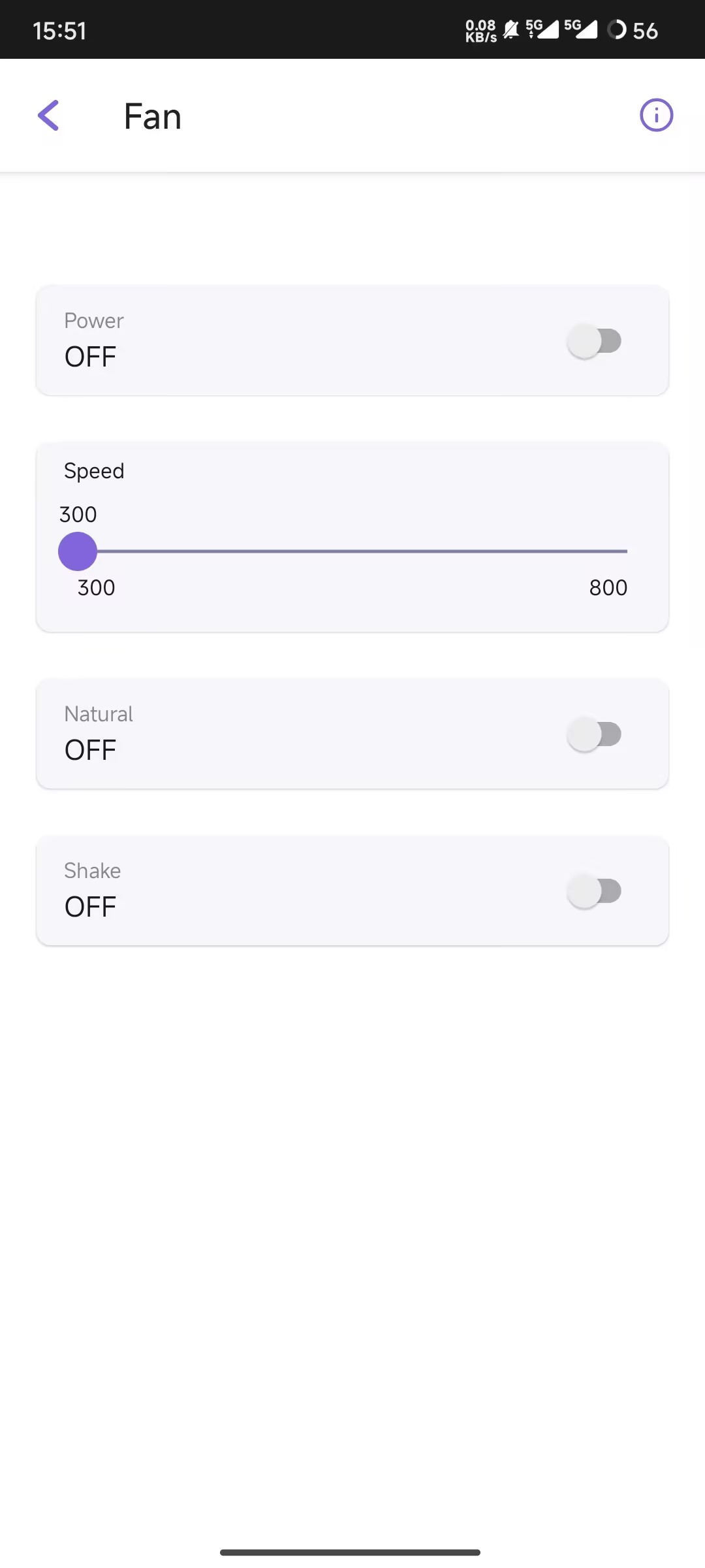
bldc_fan_rainmaker: Example of brushless motor control integrated with RainMaker. Features include
stepless speed regulation
, natural wind,
remote start/stop,
OTA,
BLE network configuration

demonstration video,
and a smart fan based on the ESP BLDC control scheme.

PDF_ESP Sensorless Square Wave ADC Solution.zip
Altium_ESP Seamless Square Wave ADC Solution.zip
PADS_ESP Sensorless Square Wave ADC Solution.zip
BOM_ESP Seamless Square Wave ADC Solution.xlsx
90885
Upgrade of Environmental Monitoring Instruments
This article mainly introduces and shares the updated content of the open source project "Multi-parameter Miniature Environmental Quality Detector Based on ESP07S" under LCSC EDA Professional Edition.
My first open-source project, "Multi-parameter Miniature Environmental Quality Detector Based on ESP07S," received a lot of love and support, garnering 26,000 views in just six months. Many fans offered various suggestions, and many successfully replicated the project and shared
their work in the comments. I'm very happy to see everyone's enthusiasm for this project. One fan in particular, Zhang from Qingdao University of Science and Technology, showed great interest in the project and made some improvements. He actively communicated with me privately, sharing his ideas. With his permission, I rebuilt a professional version of the open-source project and incorporated his improvements into it, sharing it with more embedded development enthusiasts. I thank Zhang again and hope that more like him will join in the future, making this project even more perfect. The main
improvements
include: the middle layer control board, the bottom layer power board, the casing, and the assembly method.
1. Middle Layer Control Board
: When replicating the original project, Zhang discovered that when using a stencil to apply solder paste and soldering with a heating table, some vias on the middle layer control board PCB were too large to fit solder resist, causing solder paste to leak from the vias during melting, resulting in poor soldering. This is commonly known as "solder leakage." To solve this problem, he improved two versions of my original middle layer control board PCB design. (Version numbers are V1.0 and V1.1). Version V1.0 mainly modified the position and size of various vias. Except for the large-area ground pad and antenna pad, there are no vias on the other pads, which perfectly solves the problem of solder leakage caused by vias in the pads. The component layout and model of version V1.0 are basically the same as the original version. Version V1.1 inherits the fixes of version V1.0 and also optimizes PCB routing, some component layouts, some component packages, and adds reference silkscreen for all components to facilitate the soldering of each component.
The PCB plan of the mid-layer control board V1.0 and
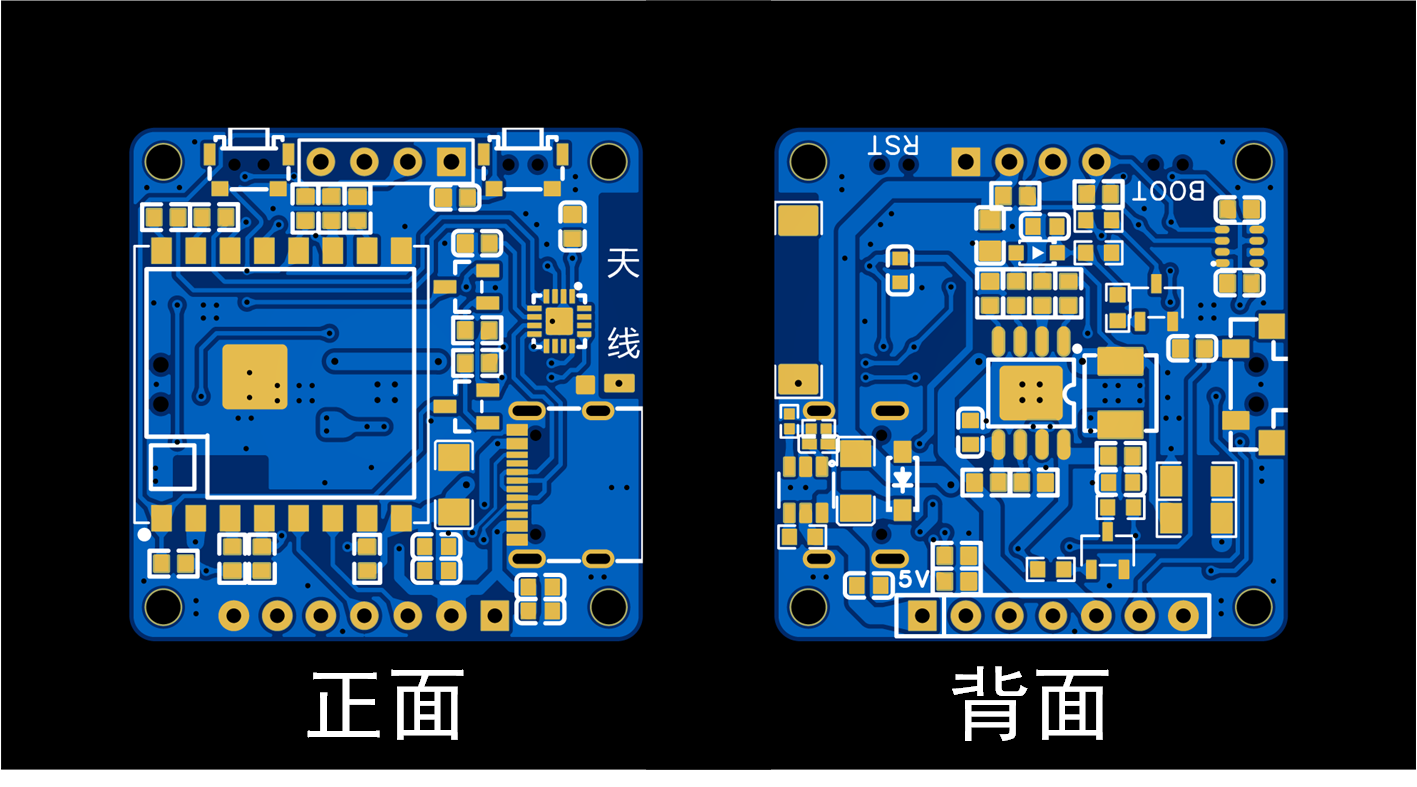
the PCB plan of the mid-layer control board V1.1

are shown. Regarding the soldering method for the mid-layer control board, Zhang proposed a new approach: using Sn42Bi57Ag1 low-temperature solder paste with a melting temperature of approximately 148 degrees Celsius. First, solder all components on the front side of the PCB (the side where the ESP07S module is located). Then, apply solder paste to the back side and place all components there. Since the ESP07S module and Type-C interface on the front side of the PCB are at the same height, the soldered PCB can be placed face down on the heating platform for soldering the back side. When removing the PCB after soldering the back side, it must be done carefully and perpendicular to the heating platform. Do not shake it excessively during removal, otherwise components may shift or fall off. This method requires a high degree of precision in the soldering process and necessitates the use of a stencil for solder application. However, the soldering process is simpler and requires fewer tools and equipment. Regarding the control of the heating table temperature during soldering, for Sn42Bi57Ag1 low-temperature solder paste, when soldering the front side of the PCB, first stabilize the heating table temperature at 170 degrees Celsius, then place the PCB on it and solder the front side. Simultaneously, adjust the heating table to 200 degrees Celsius. When it reaches 200 degrees Celsius, remove the circuit board; the front side of the PCB is now soldered. For the back side of the PCB, first stabilize the heating table temperature at 180 degrees Celsius, place the PCB face down on the heating table, and then heat to 220 degrees Celsius until the solder paste on the back of the PCB melts. Then, remove the PCB vertically; the soldering is complete. This soldering method has been tested and, apart from being slightly slower, it generally does not result in component damage.
2.
For the bottom power board, Zhang replaced the 5V boost module (finished module) with a 5V boost circuit (onboard circuit), which is more user-friendly for fans who have common resistors and capacitors on hand, and also reduces material costs. The 5V boost circuit uses the SDB628DC-DC boost power chip manufactured by LCSC Semiconductor. The SDB628 integrates an 80mΩ power MOSFET, supports a minimum input voltage of 2V to a maximum of 24V, a fixed switching frequency of 1.2MHz, an internal 4A switching current limit, and a conversion efficiency of up to 97%. The datasheet for this chip can be found by searching for C77805 on the LCSC online store. For the soldering
instructions on the bottom control board PCB

, please refer to the soldering guide in "Multi-parameter Miniature Environmental Quality Detector Based on ESP07S". The recommended soldering order is as follows: first, use a heating plate to solder all components on the front of the PCB, then use a soldering iron or hot air gun to solder the two capacitors on the back. Note that if the middle control board is version V1.1, the overall thickness of the middle control board increases because the L2 inductor on the back of the V1.1 middle control board has been changed from a 1206L package to an L0630 package. This requires the battery size on the back of the bottom power board to be modified to 802025 to be compatible with the V1.1 middle control board.
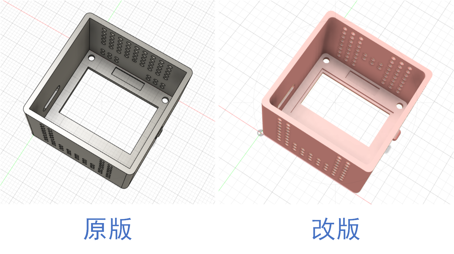
3. Shell and Assembly Method:
Zhang improved the front shell of the original shell by optimizing the screen window and buttons, and readjusting the layout of the heat dissipation holes. A recessed groove was added to the screen window area to hold the OLED display in place, which eliminates the need to paste the OLED display. The recessed groove also completely covers the non-displaying part of the OLED display, improving the overall visual experience. The document includes comparison images of
the front cover and buttons . The BOM (Revised).xlsx file contains the original sensor cover BOM, the original top-layer 0.96-inch OLED screen BOM, the V1.1 version mid-layer control board BOM, and the revised bottom-layer power board BOM. The V1.0 mid-layer control board has essentially the same components and layout as the original; refer to the BOM (Original).xlsx file. Users of the V1.1 version mid-layer control board should replace the battery on the back of the bottom-layer power board (whether original or revised) with an 802025 battery. The battery connection is the same as the 902025 battery connection in the BOM; simply select the (802025-300mAh) option to purchase. A simulated assembly demonstration video is also included.


The original shell (.STL) has been modified.
3D simulation assembly video.mp4
BOM List (Revised).xlsx
BOM List (Original Version).xlsx
PDF_Environmental Monitoring Instrument Upgrade Guide.zip
Altium Environmental Monitoring Instrument Upgrade Guide.zip
PADS Environmental Monitoring Instrument Upgrade Guide.zip
BOM - Environmental Monitoring Instrument Upgrade Guide.xlsx
90886
Gas automatic ignition switch
My elderly family member forgot to turn off the stove twice while cooking, which was too dangerous. Therefore, I made a timer switch to achieve two functions: 1. Set a timer to turn off the stove; 2. Set a timer to reduce the heat to a low setting. At the same time, it won't affect the manual cooking function.
Project Description:
This project is an automatic gas flame control switch, primarily designed to reduce the possibility of fires caused by forgetting to turn off the gas.
Open Source
License: GPL 3.0
Project Functionality
: 1. Timed flameout (initialization time 30 minutes, minimum timer 1 minute, maximum timer 120 minutes; adjustable if needed); 2. Timed flame reduction (default off, manually on); 3. Manual flameout and flame adjustment are unaffected.
(Additional note: The displayed time is the countdown time. For example, if the timed flameout is set to 10 and the timed flame reduction is set to 6, it means the flame will be reduced in 6 minutes, and then automatically shut off in 4 minutes. This wasn't originally included, but my wife's interpretation made me think it was necessary to clarify, otherwise, some people might think the flame reduction time is the duration the flame is kept low, which would be quite frustrating, haha.)
This project is being released publicly for the first time and is my original work. This project has not won any awards in other competitions.
Project Progress:
The electronic components in this project are very inexpensive; the most expensive component is likely the 3D printed parts.
Design Principles:
I. Circuit Section:
The circuit principle of this project is relatively simple. The circuit functions as follows: 1. Determine the gas switch position based on the position sensor; 2. Control the motor rotation according to the timer setting and the gas switch position, and stop at the designated position; 3. Enable the microcontroller's low-power mode from the off state.
Main control chip: PY32f002a;
Time display: TM1650 + 0.28-inch three-digit common cathode digital tube;
Motor control: YX-1818AM ;
Time setting: EC11 encoder;
Position sensor: CC6207 Hall sensor.
The principles of the above chip components will not be elaborated here; you can consult the manuals online.
I tried using AI to draw a mind map:

Based on the functions above, we need the following pins for microcontroller control: 1.
Three position sensors: W_1, W_2, W_3, corresponding to ignition switch off, pilot light, and motor initial position, respectively.
2. Two TM1650 control signals: Analog SCL, SDA
3. Three EC11 output pins: KEY_A, KEY_B, KEY_C
4. Two YX-1818AM control signals: MOTOR_1A, MOTOR_1B
5. One MOS power-off control (to reduce power consumption of peripheral circuits in conjunction with low-power mode): PA3
6. One signal LED pin: PA4
In total, 12 pins are needed
. II. Software Part
Here, I will focus on the thought process.
1. The timer switch
is crucial for timed shutdown and flame adjustment, making it the core component. I'm using a general-purpose Timer 16, set to interrupt once per minute. Two variables, TIMER1 and TIMER2, control the shutdown time and flame reduction time. When an interrupt occurs, TIMER1 is decremented, and TIMER2 is decremented. This allows adjustment of the two time intervals based on the set values of TIMER1 and TIMER2. Flame reduction is optional, so for simplicity, TIMER2 is initialized to 999. It can be adjusted downwards if needed.
2. The display
uses the EC11 button to switch between two times, with an LED indicating the current time. The default startup display is TIMER1 (30 minutes). When TIMER1 is displayed, the indicator light is off. Pressing the EC11 button switches to TIMER2, and the indicator light illuminates.
In addition, to monitor the battery level, the microcontroller's internal power monitoring channel is enabled. Since I'm using a 1s lithium battery, when the voltage drops below 3V, it displays a blob value once per second
. Position monitoring
uses three position sensors: W1 controls the low-power mode of the control chip to start and stop, and also controls the MOSFET to start and stop the peripheral circuitry; W2 indicates the position when the ignition is turned down; and W3 is the motor's initial position sensor. Whether the ignition is turned down or the gas switch is turned off, the motor must return to its initial position after the operation. The input pins of these three position sensors must be set to external trigger interrupt mode.
Below is the main program; the rest of the code is not included here. Those interested can refer to the attached source code. My programming skills are limited, so please be gentle. Kimi tidied up the following code for me and added comments:
int main(void)
{
/* Initialize EC11 counter value */
EC11_COUNT = 0;
/* Initialize HAL library */
HAL_Init();
/* Configure ADC */
APP_ADCConfig();
/* Configure system clock */
APP_SystemClockConfig();
/* Enable clocks for GPIOA, B, and F */
__HAL_RCC_GPIOA_CLK_ENABLE();
__HAL_RCC_GPIOB_CLK_ENABLE();
__HAL_RCC_GPIOF_CLK_ENABLE();
/* Initialize EC11 pins */
EC11_PIN_INIT();
/* Initialize TIM16 */
TIM16Config();
/* Initialize LED */
MYLED_Init();
/* Initialize I2C pins */
I2C_PIN_INIT();
/* Configure external interrupts */
Configure_EXTI();
/* Initialize external interrupts for W1 and W3 */
W1_W3_EXTIConfig();
/* Initialize GPIO related to CC6207 */
GPIO_CC6207_INIT();
/* Initialize GPIO related to motor control */
MOTOR_GPIO_INIT();
/* Initialize TM1650 display driver */
TM1650_INIT();
/* Set TM1650 to enter sleep mode */
TM1650_SET(SYS_ADD, SYS_SLEEP);
/* Main loop */
while (1)
{
/* Get current time */
TIME = HAL_GetTick();
/* Reinitialize TM1650 */
TM1650_INIT();
/* Start ADC conversion */
HAL_ADC_Start(&hadc);
/* Wait for ADC conversion to complete */
HAL_ADC_PollForConversion(&hadc, 1000000);
/* Get ADC value */
adc_value = HAL_ADC_GetValue(&hadc);
/* Calculate VCC voltage */
T_VCC = (4095 * 1.2) / adc_value;
/* If the battery voltage is below 3V, display a low battery warning */
if (T_VCC
{
/* Switch between displaying a low battery warning and the current timer every second */
if ((TIME % 2000)
{
TIM1650_DIS(ADD1, 10); // Display 'B'
TIM1650_DIS(ADD2, 11); // Display 'L'
TIM1650_DIS(ADD3, 12); // Display 'O'
}
else
{
/* Display the value of TIMER1 or TIMER2 according to DSP_FLAG */
if (DSP_FLAG)
{
TIM1650_DIS(ADD1, TIMER1 / 100);
TIM1650_DIS(ADD2, (TIMER1 / 10) % 10);
TIM1650_DIS(ADD3, TIMER1 % 10);
}
else
{
TIM1650_DIS(ADD1, TIMER2 / 100);
TIM1650_DIS(ADD2, (TIMER2 / 10) % 10);
TIM1650_DIS(ADD3, TIMER2 % 10);
}
}
}
else
{
/* If the battery voltage is normal, display normal timing */
if (DSP_FLAG)
{
TIM1650_DIS(ADD1, TIMER1 / 100);
TIM1650_DIS(ADD2, (TIMER1 / 10) % 10);
TIM1650_DIS(ADD3, TIMER1 % 10);
}
else
{
TIM1650_DIS(ADD1, TIMER2 / 100);
TIM1650_DIS(ADD2, (TIMER2 / 10) % 10);
TIM1650_DIS(ADD3, TIMER2 % 10);
}
}
/* If W1 is high and TIMER1 is 0, start the motor to move forward */
if (W1 == 1 && TIMER1
{
MOTOR_FORWARD();
}
/* If W1 is low and W3 is high, the motor moves backward */ if
(W1 == 0 && W3 == 1) {
for
(int i = 0
;
...
MOTOR_STOP();
TM1650_SET(SYS_ADD, SYS_SLEEP);
TIMER1 = 30;
// Turn off the power of TM1650, W2, and W3
HAL_GPIO_WritePin(GPIOA, GPIO_PIN_All, GPIO_PIN_RESET);
HAL_GPIO_WritePin(LED_PORT, LED_PIN, GPIO_PIN_SET);
HAL_GPIO_WritePin(GPIOB, GPIO_PIN_All, GPIO_PIN_RESET);
HAL_GPIO_WritePin(GPIOF, GPIO_PIN_All, GPIO_PIN_RESET);
PWR_STOP_MODE(); // Enter low-power mode
}
/* If TIMER2 is 0 and TIMER1 is greater than 0, perform special operations */
if (TIMER2 0)
{
TIMER2 = 0;
while (TIMER2_FLAG == 0)
{
MOTOR_BACKWARD(); // Motor moves backward
}
if (TIMER2_FLAG == 1)
{
while (W3 == 1)
{
MOTOR_FORWARD(); // Motor moves forward
}
MOTOR_STOP(); // Stop the motor
TIMER2 = 999; // Reset TIMER2
}
}
} }
III
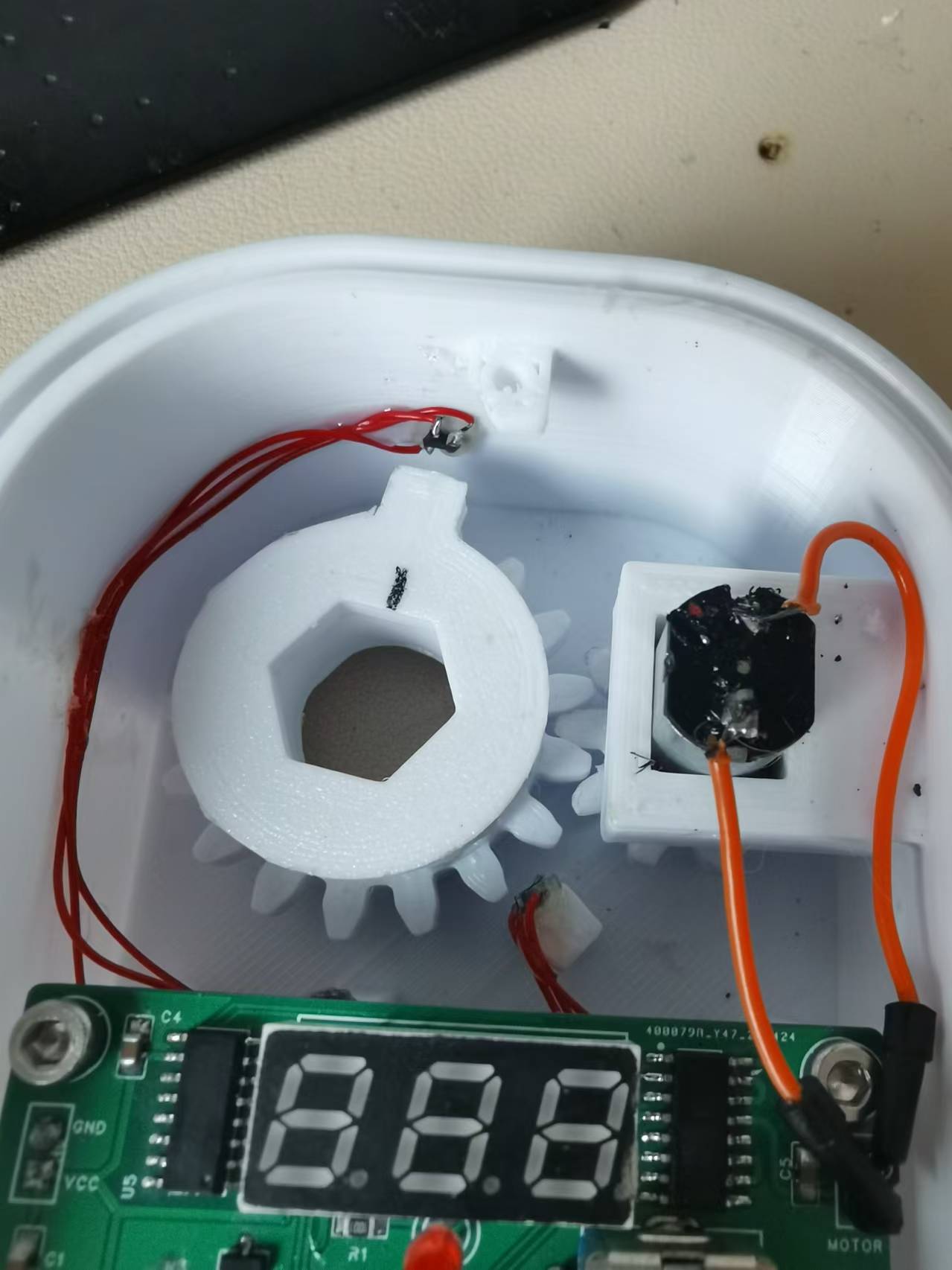
. Housing and Mechanical Design
The mechanical design of this timer switch is actually the key, because it needs to control automatically without affecting manual control. After thinking for a long time, I suddenly had a flash of inspiration: the transmission can be changed to up and down transmission. I designed the mechanical structure using FreeCAD and took a screenshot to briefly explain: The two large parts in the picture are obvious, namely the housing and the top cover. There is also a square part below, which is the external battery box. You can make screw holes on both sides of the battery box with bricks and screw it onto the housing. The main part to explain is the parts inside the housing: The bright green one on the right is an N20 geared motor. This geared motor should be 3V, and the larger the reduction ratio, the better. Mine is about 40 revolutions per minute. On the left are the main gear and the driven wheel that drive the main shaft, designed in two layers. The driven wheel has a 3mm diameter neodymium magnet embedded in the center of its square protrusion. The main gear has a boss, and another 3mm diameter neodymium magnet is embedded in the side of the boss. The central shaft connects the stove's rotating shaft and the original rotary knob; its hexagonal outer diameter allows it to be driven by the main shaft. The central hole of the main gear is circular, so it doesn't affect the main gear's operation, ensuring manual control is unaffected. Currently, the image shows the driven wheel protrusion pointing towards the location of the W1 sensor, and the two square pillars on the lower casing are the locations for the W2 and W3 sensors. I directly glued these three sensors to the casing.
Because it was 3D printed, the front of the casing was designed with two layers, primarily to increase air insulation to mimic the deformation of the inner layer, and the outermost layer can also be covered with aluminum foil or fire-retardant tape for further insulation. Also, I didn't pay attention to the position of the screw when drawing the diagram; it's pressing against the top cover, but it's not a big problem. Just cut off a portion with diagonal pliers. Like in the picture below, just cut off a corner at an angle.

Below is what the internal structure looks like after installation:
Standby current in low power mode: There aren't any particularly noteworthy
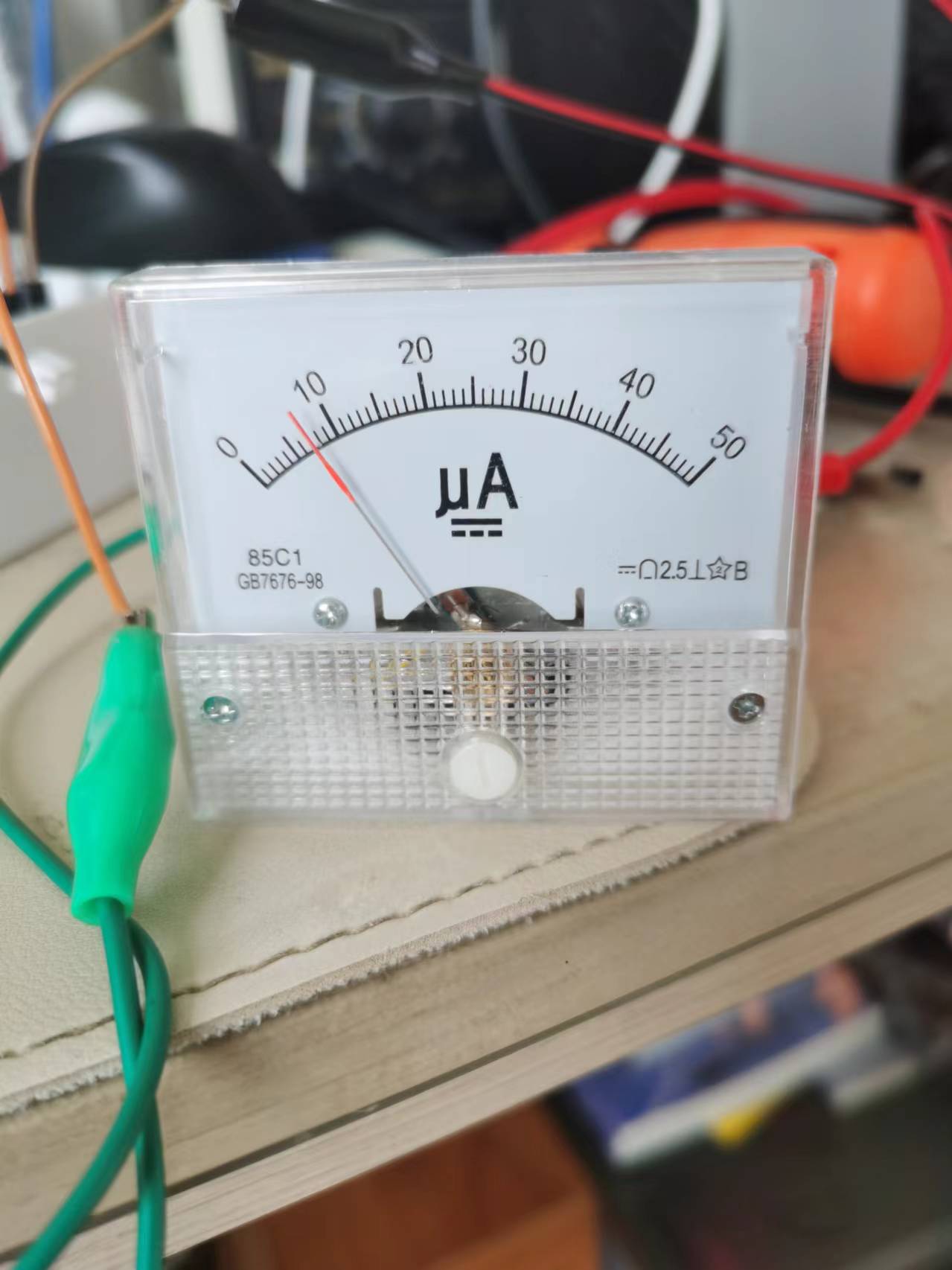
precautions
. I just don't know where the program is conflicting; the `delay` function can't be used. Using it prevents entering low power mode, so I used an empty loop for a simple delay. I'm too lazy to investigate further. For amateurs like us, we shouldn't have too high expectations; as long as it works, that's fine, right?
Also, I'm using a 450mAh lithium battery. When fully charged on May 19th, it was 4.15V. After 20 days, I just tested it, and it's still at 3.9V. So, it should last at least 3 months. If you think that's too short, you can replace it with a larger battery.
The only thing to note is that I'm using version 1.1.0 of the py32 pack; higher versions may cause compilation errors. The pack is attached.
Other
demo video links:
https://www.bilibili.com/video/BV1cs421T7tq/?spm_id_from=333.999.0.0&vd_source=6928ed1f7a603fdcf8a1d375c0dbc79c
Project attachments: Entries participating in the event must upload the relevant program attachments to an open-source platform or their personal code storage cloud. The maximum upload size for attachments is 50MB (please do not upload to the LCSC workspace, as there are limitations).
afa3527652f2028807992d7958fc376a.mp4
3D printing files.zip
Project files.zip
Puya.PY32F0xx_DFP.1.1.0.zip
PDF_Gas Automatic Ignition Switch.zip
Altium_Gas Automatic Ignition Switch.zip
PADS_Gas Automatic Ignition Switch.zip
BOM_Gas Automatic Ignition Control Switch.xlsx
90887
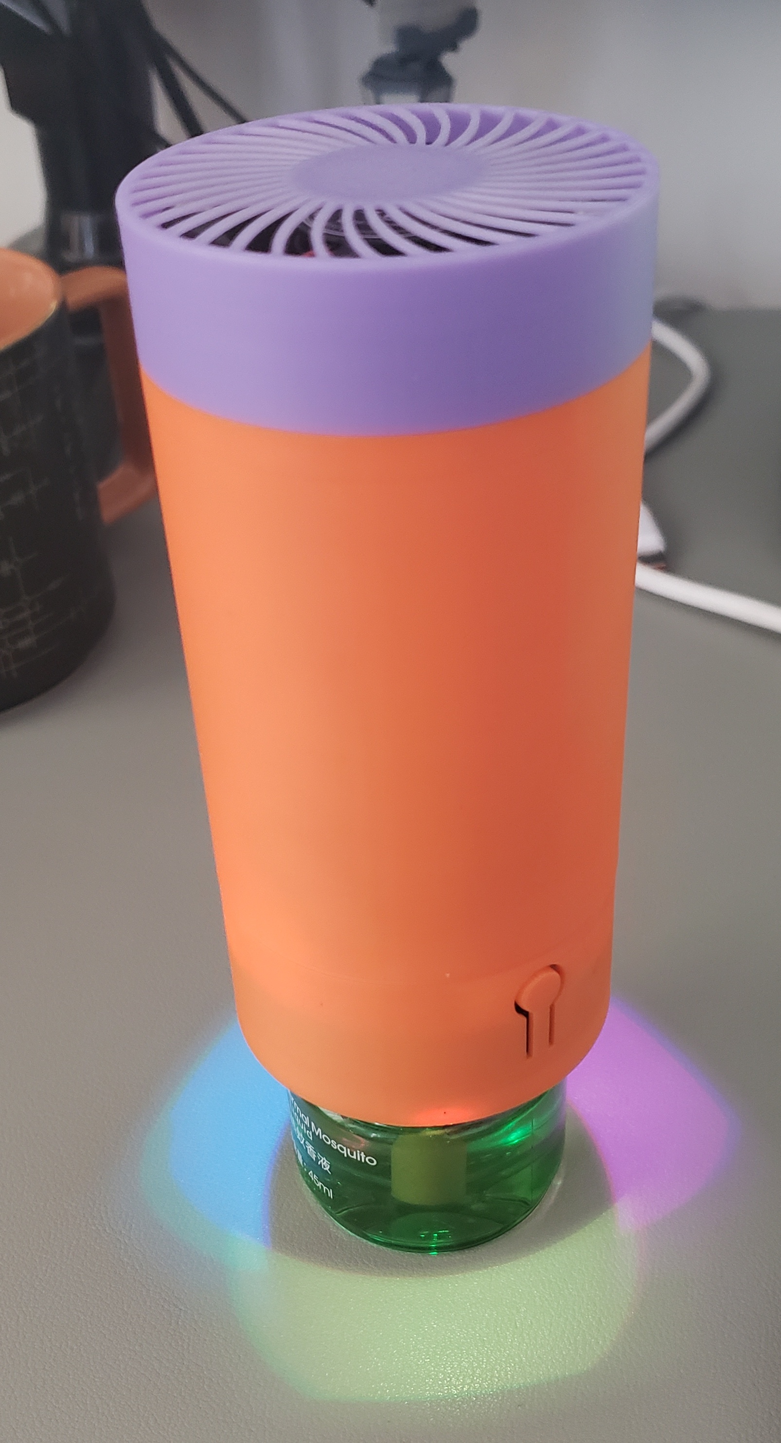
Lithium battery powered electric mosquito repellent liquid repels and kills mosquitoes.
Portable mosquito repellent liquid powered by lithium battery
It's that time of year again when mosquitoes bite, so it's time to get some effective tools to repel them. The mosquito repellent
we use at home is a 220V electric heated liquid mosquito repellent, which gets very hot.
It's very inconvenient to use outdoors;
a battery-powered one would be much more convenient.
Currently, it has a built-in 18650 lithium battery. This portable mosquito repellent
uses a fan to evaporate the mosquito repellent liquid.
When not in use, it can be unscrewed and used as a night light or small fan. It currently has three fan speed settings, which can be modified by the user.

Open source license
: Attribution-NonCommercial-ShareAlike 4.0 International (CC BY-NC-SA 4.0).
We welcome everyone to create their own versions, but we hope you will adhere to the open source license.
For derivative works, please clearly indicate the author and source address in a prominent position.
For derivative open source projects, please clearly indicate the modifications to facilitate reference and contribution by others, and to help distinguish them from the original.
Without the original author's permission, the original project and derivative projects may not be used for commercial purposes.
We hope everyone will retain the original open source author information in the PCB or other open source files.
Demonstration:
https://www.bilibili.com/video/BV1iM4m1U7WM
Material Preparation:
In addition to purchasing the BOM exported from LCSC EDA, you also need to purchase the following materials:
5V 4010 fan SHENG FENG (胜丰宏). Cooling Fan SF4010B2M5 40*40*10mm DC5V, 7000rpm [Price, Purchase, Pictures] - LCSC MRO Industrial Products (szlcsc.com)
18650 Lithium Battery KAMCY/Kangsheng, Cylindrical Lithium Battery, 3.7V, 18650-2600mAh-3.7VC, 1 piece [Price, Purchase, Pictures] - LCSC MRO Industrial Products (szlcsc.com)
M1.7*10 Self-Tapping Screws 3 pieces
M3*14 Countersunk Screws 4 pieces
Firmware Download
Reference Air001 Development Board Introduction | AirMCU (luatos.com) allows for serial port downloading and
development using the Arduino environment
, or via an emulator. The board has pre-reserved ports. The main
hardware
controller is the Heze Air001, which is relatively inexpensive, supports Arduino development, and requires fewer external components.
The charging chip is an IP5306, used to charge the 18650 lithium battery and provide main power to the system
. The fan is a 4010 fan controlled by PWM.
Power
buttons: double-click to power off, single-click to power on.
Button 1: Fan control, three-stage, short press.
Button 2: Lighting effect, short press
effect
. Due to limited testing time and varying mosquito numbers, no mosquito bites were observed during testing.
Further testing is pending feedback.
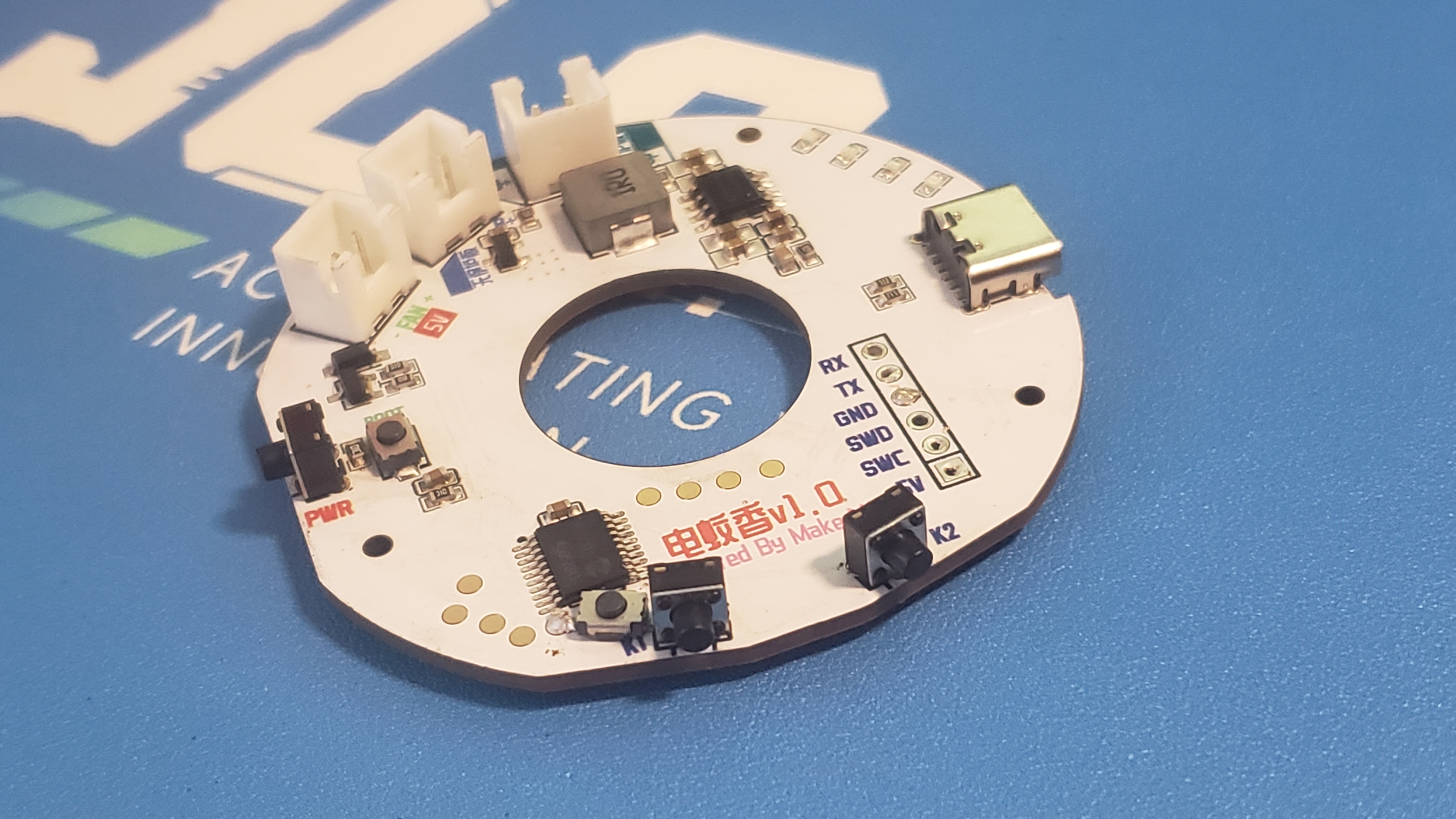
PCB layout.
1.6mm thickness,
latest version: v1.1.
Note: There are two 18650 sockets on the board; choose one as needed. One is for 18650 batteries with a protection board, and the other is for batteries without a protection board.
Pay attention to the positive and negative terminals of the battery and fan; do not reverse them.
3D printing
files can be downloaded here: https://makerworld.com/zh/models/479319#profileId-390663
ElecMosquito.ino
ElecMosquito.ino.bin
ElecMosquito.ino.hex
PDF_Lithium Battery Powered Electric Mosquito Repellent Liquid.zip
Altium lithium battery powered electric mosquito repellent liquid.zip
PADS_Lithium Battery Powered Electric Mosquito Repellent Liquid.zip
BOM_Lithium battery powered electric mosquito repellent liquid.xlsx
90888
electronic


 京公网安备 11010802033920号

 MN-HK95-20XC5


