Project Description:
This project is an automatic gas flame control switch, primarily designed to reduce the possibility of fires caused by forgetting to turn off the gas.
Open Source
License: GPL 3.0
Project Functionality
: 1. Timed flameout (initialization time 30 minutes, minimum timer 1 minute, maximum timer 120 minutes; adjustable if needed); 2. Timed flame reduction (default off, manually on); 3. Manual flameout and flame adjustment are unaffected.
(Additional note: The displayed time is the countdown time. For example, if the timed flameout is set to 10 and the timed flame reduction is set to 6, it means the flame will be reduced in 6 minutes, and then automatically shut off in 4 minutes. This wasn't originally included, but my wife's interpretation made me think it was necessary to clarify, otherwise, some people might think the flame reduction time is the duration the flame is kept low, which would be quite frustrating, haha.)
This project is being released publicly for the first time and is my original work. This project has not won any awards in other competitions.
Project Progress:
The electronic components in this project are very inexpensive; the most expensive component is likely the 3D printed parts.
Design Principles:
I. Circuit Section:
The circuit principle of this project is relatively simple. The circuit functions as follows: 1. Determine the gas switch position based on the position sensor; 2. Control the motor rotation according to the timer setting and the gas switch position, and stop at the designated position; 3. Enable the microcontroller's low-power mode from the off state.
Main control chip: PY32f002a;
Time display: TM1650 + 0.28-inch three-digit common cathode digital tube;
Motor control: YX-1818AM ;
Time setting: EC11 encoder;
Position sensor: CC6207 Hall sensor.
The principles of the above chip components will not be elaborated here; you can consult the manuals online.
I tried using AI to draw a mind map:

Based on the functions above, we need the following pins for microcontroller control: 1.
Three position sensors: W_1, W_2, W_3, corresponding to ignition switch off, pilot light, and motor initial position, respectively.
2. Two TM1650 control signals: Analog SCL, SDA
3. Three EC11 output pins: KEY_A, KEY_B, KEY_C
4. Two YX-1818AM control signals: MOTOR_1A, MOTOR_1B
5. One MOS power-off control (to reduce power consumption of peripheral circuits in conjunction with low-power mode): PA3
6. One signal LED pin: PA4
In total, 12 pins are needed
. II. Software Part
Here, I will focus on the thought process.
1. The timer switch
is crucial for timed shutdown and flame adjustment, making it the core component. I'm using a general-purpose Timer 16, set to interrupt once per minute. Two variables, TIMER1 and TIMER2, control the shutdown time and flame reduction time. When an interrupt occurs, TIMER1 is decremented, and TIMER2 is decremented. This allows adjustment of the two time intervals based on the set values of TIMER1 and TIMER2. Flame reduction is optional, so for simplicity, TIMER2 is initialized to 999. It can be adjusted downwards if needed.
2. The display
uses the EC11 button to switch between two times, with an LED indicating the current time. The default startup display is TIMER1 (30 minutes). When TIMER1 is displayed, the indicator light is off. Pressing the EC11 button switches to TIMER2, and the indicator light illuminates.
In addition, to monitor the battery level, the microcontroller's internal power monitoring channel is enabled. Since I'm using a 1s lithium battery, when the voltage drops below 3V, it displays a blob value once per second
. Position monitoring
uses three position sensors: W1 controls the low-power mode of the control chip to start and stop, and also controls the MOSFET to start and stop the peripheral circuitry; W2 indicates the position when the ignition is turned down; and W3 is the motor's initial position sensor. Whether the ignition is turned down or the gas switch is turned off, the motor must return to its initial position after the operation. The input pins of these three position sensors must be set to external trigger interrupt mode.
Below is the main program; the rest of the code is not included here. Those interested can refer to the attached source code. My programming skills are limited, so please be gentle. Kimi tidied up the following code for me and added comments:
int main(void)
{
/* Initialize EC11 counter value */
EC11_COUNT = 0;
/* Initialize HAL library */
HAL_Init();
/* Configure ADC */
APP_ADCConfig();
/* Configure system clock */
APP_SystemClockConfig();
/* Enable clocks for GPIOA, B, and F */
__HAL_RCC_GPIOA_CLK_ENABLE();
__HAL_RCC_GPIOB_CLK_ENABLE();
__HAL_RCC_GPIOF_CLK_ENABLE();
/* Initialize EC11 pins */
EC11_PIN_INIT();
/* Initialize TIM16 */
TIM16Config();
/* Initialize LED */
MYLED_Init();
/* Initialize I2C pins */
I2C_PIN_INIT();
/* Configure external interrupts */
Configure_EXTI();
/* Initialize external interrupts for W1 and W3 */
W1_W3_EXTIConfig();
/* Initialize GPIO related to CC6207 */
GPIO_CC6207_INIT();
/* Initialize GPIO related to motor control */
MOTOR_GPIO_INIT();
/* Initialize TM1650 display driver */
TM1650_INIT();
/* Set TM1650 to enter sleep mode */
TM1650_SET(SYS_ADD, SYS_SLEEP);
/* Main loop */
while (1)
{
/* Get current time */
TIME = HAL_GetTick();
/* Reinitialize TM1650 */
TM1650_INIT();
/* Start ADC conversion */
HAL_ADC_Start(&hadc);
/* Wait for ADC conversion to complete */
HAL_ADC_PollForConversion(&hadc, 1000000);
/* Get ADC value */
adc_value = HAL_ADC_GetValue(&hadc);
/* Calculate VCC voltage */
T_VCC = (4095 * 1.2) / adc_value;
/* If the battery voltage is below 3V, display a low battery warning */
if (T_VCC
{
/* Switch between displaying a low battery warning and the current timer every second */
if ((TIME % 2000)
{
TIM1650_DIS(ADD1, 10); // Display 'B'
TIM1650_DIS(ADD2, 11); // Display 'L'
TIM1650_DIS(ADD3, 12); // Display 'O'
}
else
{
/* Display the value of TIMER1 or TIMER2 according to DSP_FLAG */
if (DSP_FLAG)
{
TIM1650_DIS(ADD1, TIMER1 / 100);
TIM1650_DIS(ADD2, (TIMER1 / 10) % 10);
TIM1650_DIS(ADD3, TIMER1 % 10);
}
else
{
TIM1650_DIS(ADD1, TIMER2 / 100);
TIM1650_DIS(ADD2, (TIMER2 / 10) % 10);
TIM1650_DIS(ADD3, TIMER2 % 10);
}
}
}
else
{
/* If the battery voltage is normal, display normal timing */
if (DSP_FLAG)
{
TIM1650_DIS(ADD1, TIMER1 / 100);
TIM1650_DIS(ADD2, (TIMER1 / 10) % 10);
TIM1650_DIS(ADD3, TIMER1 % 10);
}
else
{
TIM1650_DIS(ADD1, TIMER2 / 100);
TIM1650_DIS(ADD2, (TIMER2 / 10) % 10);
TIM1650_DIS(ADD3, TIMER2 % 10);
}
}
/* If W1 is high and TIMER1 is 0, start the motor to move forward */
if (W1 == 1 && TIMER1
{
MOTOR_FORWARD();
}
/* If W1 is low and W3 is high, the motor moves backward */ if
(W1 == 0 && W3 == 1) {
for
(int i = 0
;
...
MOTOR_STOP();
TM1650_SET(SYS_ADD, SYS_SLEEP);
TIMER1 = 30;
// Turn off the power of TM1650, W2, and W3
HAL_GPIO_WritePin(GPIOA, GPIO_PIN_All, GPIO_PIN_RESET);
HAL_GPIO_WritePin(LED_PORT, LED_PIN, GPIO_PIN_SET);
HAL_GPIO_WritePin(GPIOB, GPIO_PIN_All, GPIO_PIN_RESET);
HAL_GPIO_WritePin(GPIOF, GPIO_PIN_All, GPIO_PIN_RESET);
PWR_STOP_MODE(); // Enter low-power mode
}
/* If TIMER2 is 0 and TIMER1 is greater than 0, perform special operations */
if (TIMER2 0)
{
TIMER2 = 0;
while (TIMER2_FLAG == 0)
{
MOTOR_BACKWARD(); // Motor moves backward
}
if (TIMER2_FLAG == 1)
{
while (W3 == 1)
{
MOTOR_FORWARD(); // Motor moves forward
}
MOTOR_STOP(); // Stop the motor
TIMER2 = 999; // Reset TIMER2
}
}
} }
III
. Housing and Mechanical Design
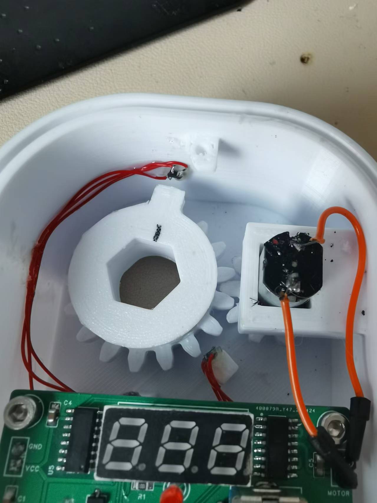
The mechanical design of this timer switch is actually the key, because it needs to control automatically without affecting manual control. After thinking for a long time, I suddenly had a flash of inspiration: the transmission can be changed to up and down transmission. I designed the mechanical structure using FreeCAD and took a screenshot to briefly explain: The two large parts in the picture are obvious, namely the housing and the top cover. There is also a square part below, which is the external battery box. You can make screw holes on both sides of the battery box with bricks and screw it onto the housing. The main part to explain is the parts inside the housing: The bright green one on the right is an N20 geared motor. This geared motor should be 3V, and the larger the reduction ratio, the better. Mine is about 40 revolutions per minute. On the left are the main gear and the driven wheel that drive the main shaft, designed in two layers. The driven wheel has a 3mm diameter neodymium magnet embedded in the center of its square protrusion. The main gear has a boss, and another 3mm diameter neodymium magnet is embedded in the side of the boss. The central shaft connects the stove's rotating shaft and the original rotary knob; its hexagonal outer diameter allows it to be driven by the main shaft. The central hole of the main gear is circular, so it doesn't affect the main gear's operation, ensuring manual control is unaffected. Currently, the image shows the driven wheel protrusion pointing towards the location of the W1 sensor, and the two square pillars on the lower casing are the locations for the W2 and W3 sensors. I directly glued these three sensors to the casing.
Because it was 3D printed, the front of the casing was designed with two layers, primarily to increase air insulation to mimic the deformation of the inner layer, and the outermost layer can also be covered with aluminum foil or fire-retardant tape for further insulation. Also, I didn't pay attention to the position of the screw when drawing the diagram; it's pressing against the top cover, but it's not a big problem. Just cut off a portion with diagonal pliers. Like in the picture below, just cut off a corner at an angle.

Below is what the internal structure looks like after installation:
Standby current in low power mode: There aren't any particularly noteworthy
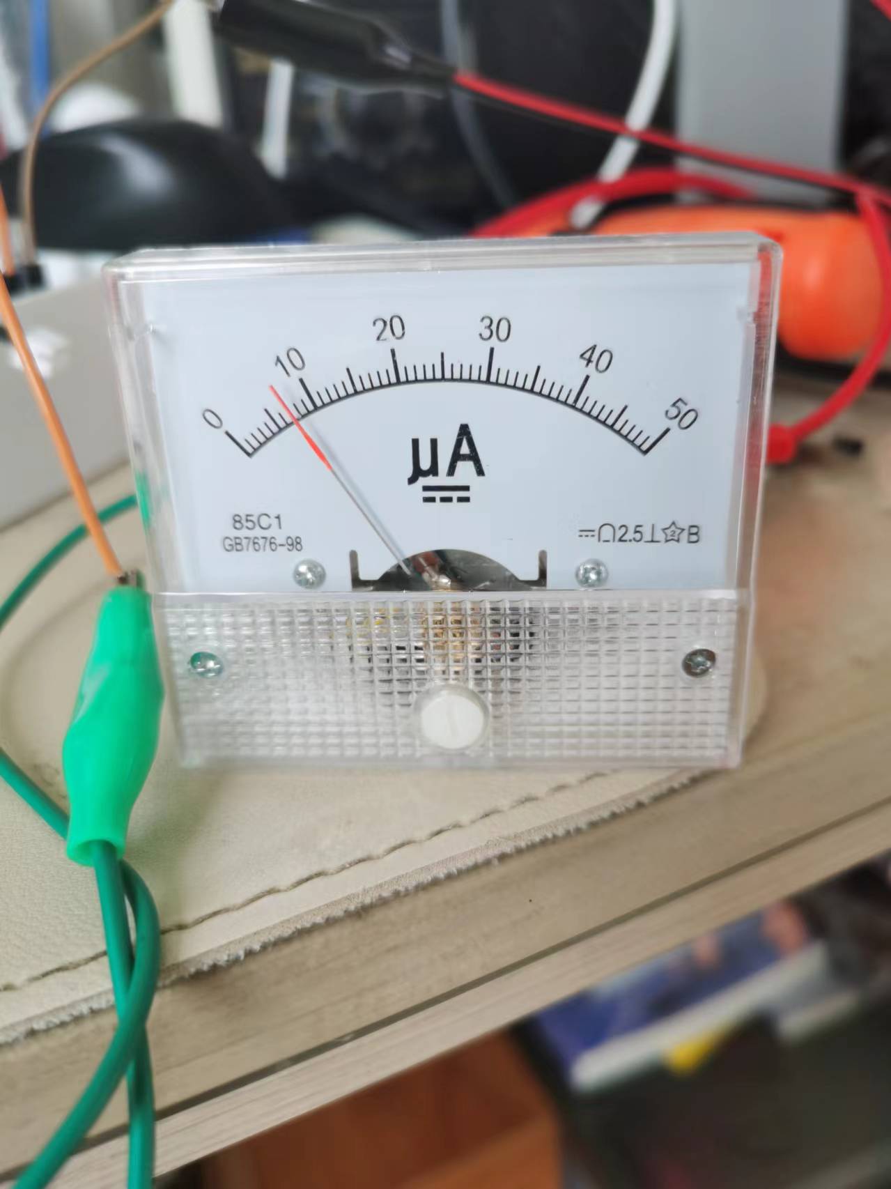
precautions
. I just don't know where the program is conflicting; the `delay` function can't be used. Using it prevents entering low power mode, so I used an empty loop for a simple delay. I'm too lazy to investigate further. For amateurs like us, we shouldn't have too high expectations; as long as it works, that's fine, right?
Also, I'm using a 450mAh lithium battery. When fully charged on May 19th, it was 4.15V. After 20 days, I just tested it, and it's still at 3.9V. So, it should last at least 3 months. If you think that's too short, you can replace it with a larger battery.
The only thing to note is that I'm using version 1.1.0 of the py32 pack; higher versions may cause compilation errors. The pack is attached.
Other
demo video links:
https://www.bilibili.com/video/BV1cs421T7tq/?spm_id_from=333.999.0.0&vd_source=6928ed1f7a603fdcf8a1d375c0dbc79c
Project attachments: Entries participating in the event must upload the relevant program attachments to an open-source platform or their personal code storage cloud. The maximum upload size for attachments is 50MB (please do not upload to the LCSC workspace, as there are limitations).


 京公网安备 11010802033920号

 XZFBB55W-2


