This project
utilizes an STM32H750XBH6 core board with a DDR4-DIMM interface. This interface connector is inexpensive, easy to use, and highly portable. It
is licensed under
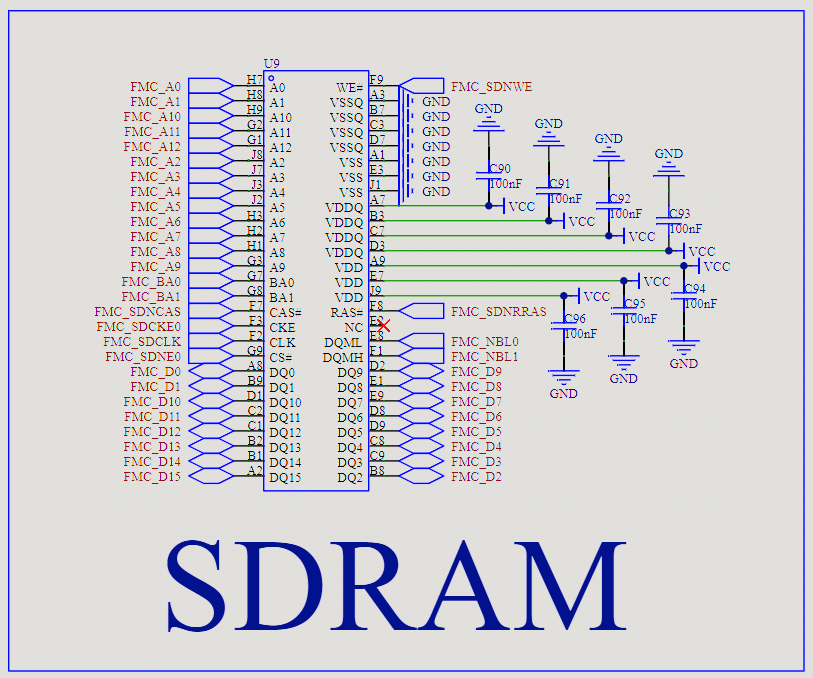
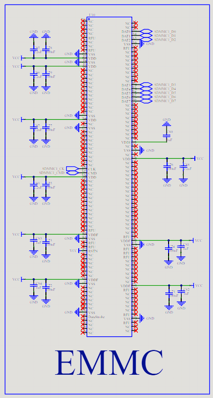
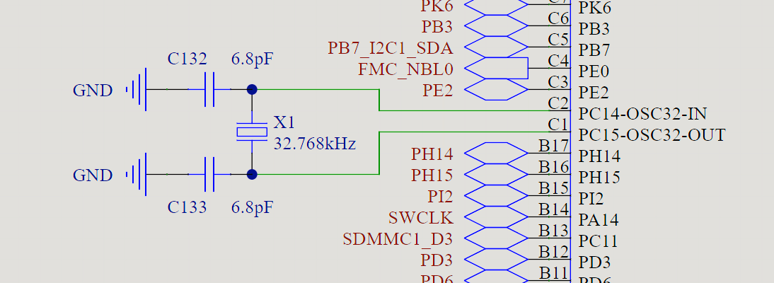
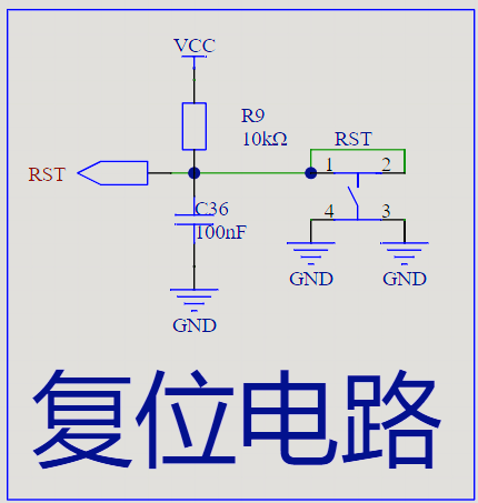
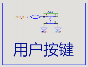
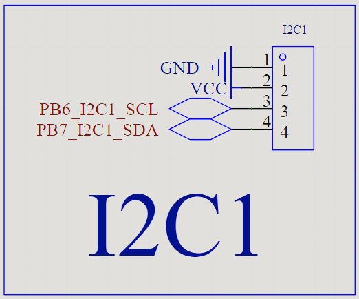
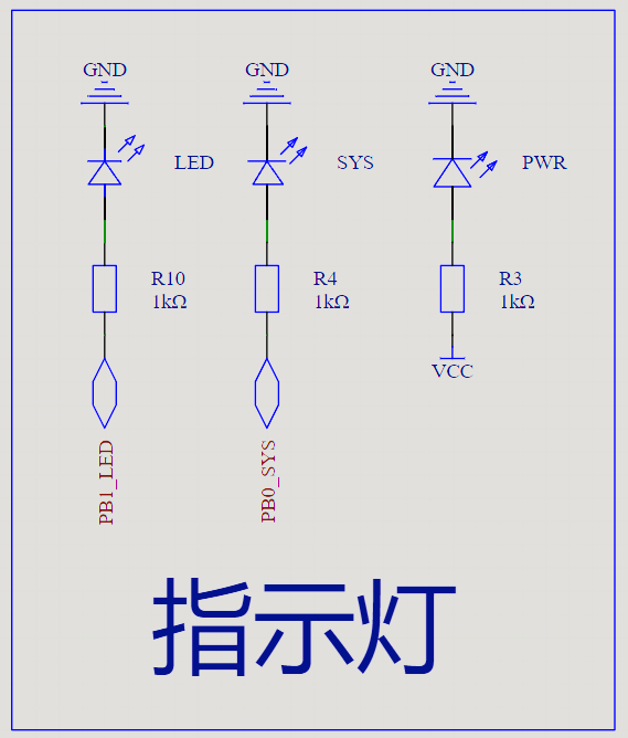
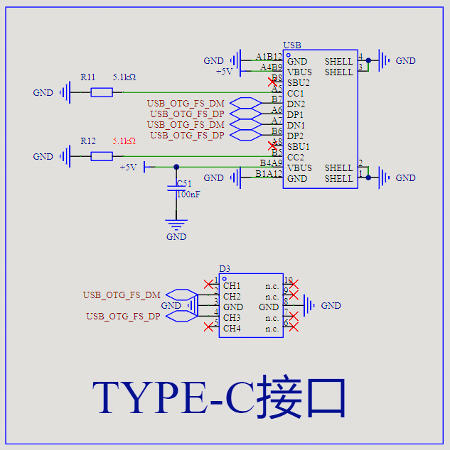
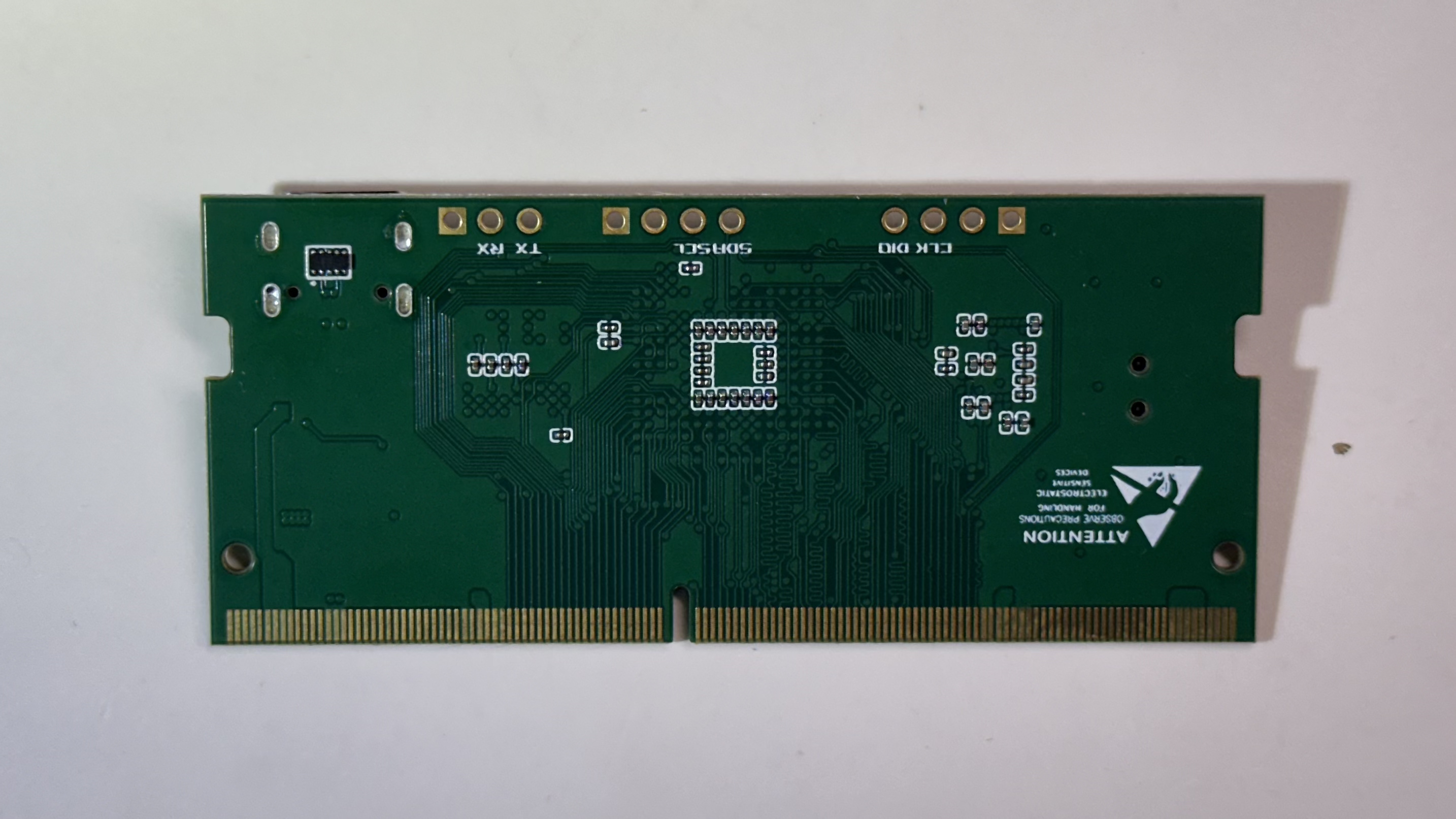
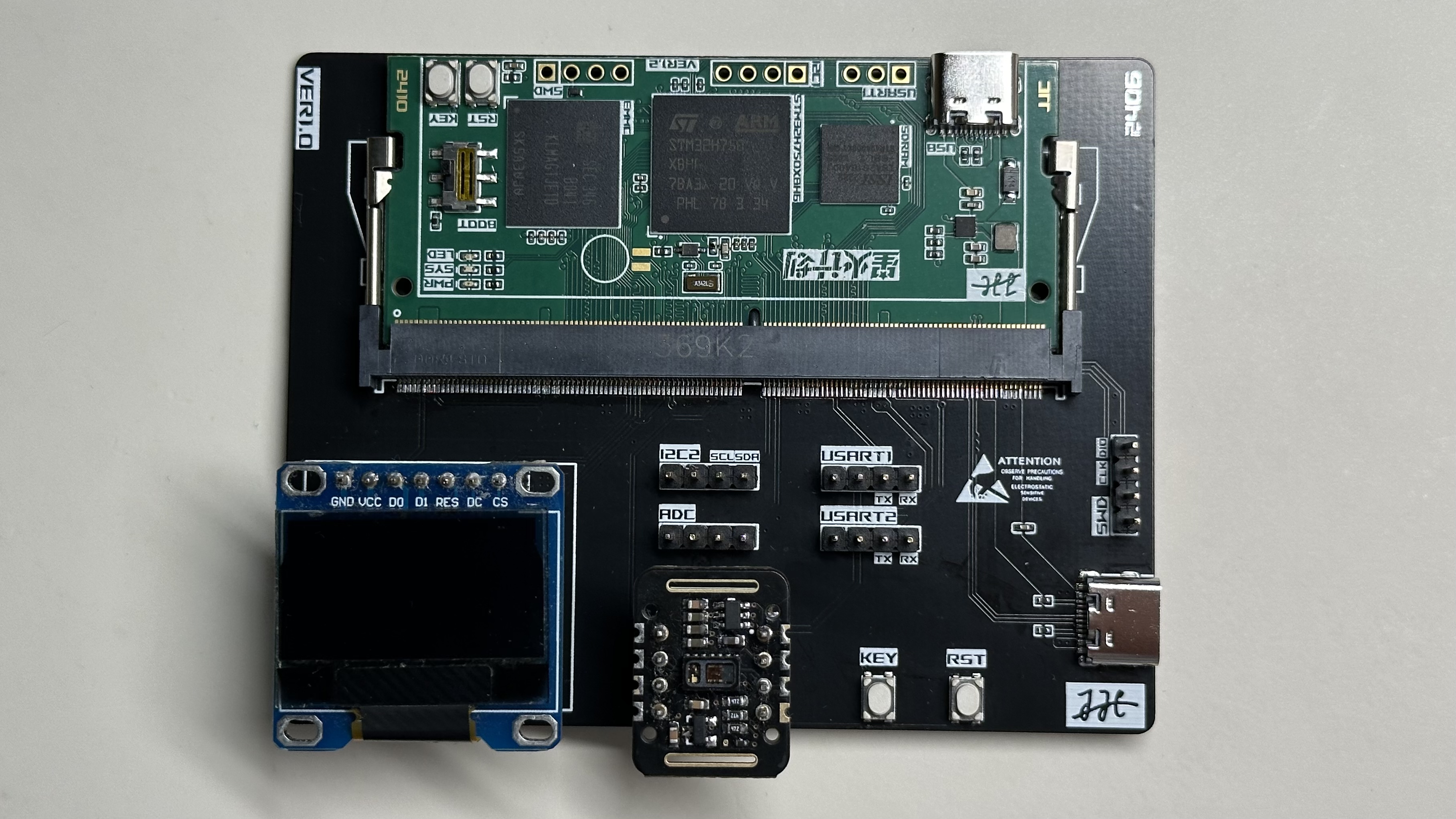
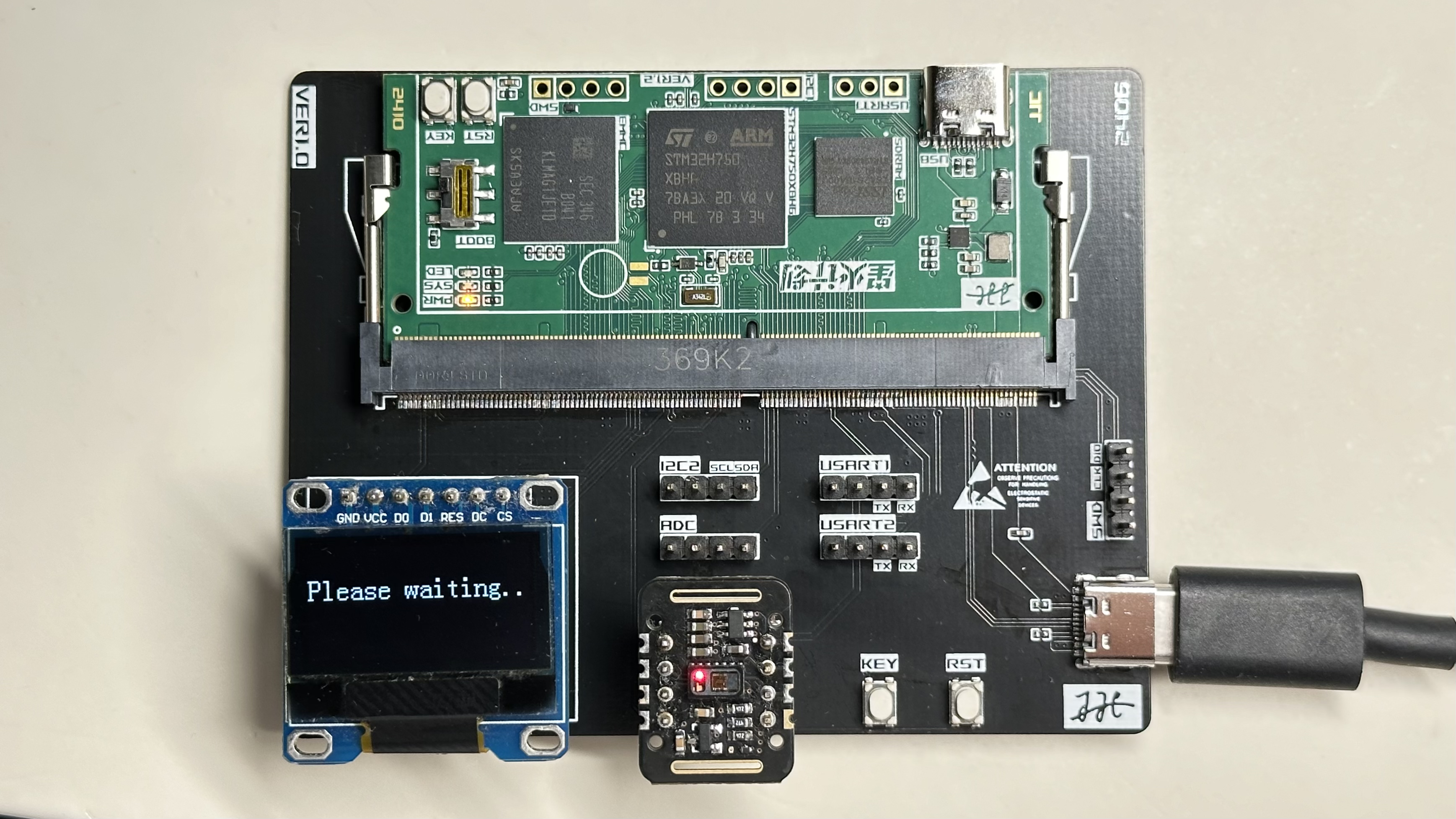
GPL 3.0. The core board of this project aims for versatility, using a self-designed baseboard to implement an OLED heart rate and pulse oximeter demo and provide a program demo based on the core board hardware. This is the first public release of this project ; it is an original work by the author and has not won any awards in other competitions. The project is fully designed and completed. The design principles here mainly explain the core board: STM32 SDRAM, 8MB and 16MB are interchangeable; eMMC uses KLM8G1GETF-B041 for testing; an external low-speed crystal oscillator circuit is available, but it is recommended to add an external high-speed crystal oscillator; RTC backup power uses a rechargeable surface-mount battery; BOOT mode selection switch is on the button side for normal startup mode ; when using USB programming, the core board's TYPE-C port must be used, and the switch must be on the gold finger side before resetting; reset circuit ; user button ; SWD debugging interface; I2C interface; serial port 1 can be used for programming; indicator lights ; power supply : the core board only requires a 3.3V power supply ; interface: TYPE-C interface, add ESD device; DDR4-DIMM gold finger; software description: the currently provided demos include: LED test program (SYS_LED.zip); 8MB and 16MB SDRAM different speed test program (zip file starting with SDRAM); USB virtual serial port program (USB_COM.zip). This document includes a physical demonstration of an STM32 virtual USB flash drive program (USBMSC.zip) paired with an OLED heart rate and pulse oximetry demo program (MAX30102_OLED.zip) with a baseboard. It also includes the front and back of the core board , the heart rate baseboard , and the operating status of the baseboard. Design considerations include: Soldering sequence : It is recommended to use high-temperature tape to cover the gold fingers during soldering; solder the DDR4 slot first on the baseboard; the TYPE-C port is for power supply only; it is recommended to complete the power supply section first and ensure it is working correctly. If using eMMC, solder the eMMC first, as its solder balls are smaller and more difficult to solder. After soldering the STM32 controller, you can burn the TEST program to test the solder joint connectivity. The pins connecting the SDRAM and STM32 will flip every 500ms. Soldering the SDRAM may cause test failures due to high temperatures immediately after soldering; wait until it cools to room temperature before testing again. Complete the remaining components on the front (excluding the main components). Use a hot air gun to solder the capacitors on the back. Finally, solder the main components, backup battery, and TYPE-C interface. Other heart rate and pulse oximeter demos: [Modular heart rate and pulse oximeter based on STM32, open source]. https://www.bilibili.com/video/BV1YA4m1F7hk/?share_source=copy_web


 京公网安备 11010802033920号

 EMS22D53-C20-WW3


