Version: From April 1, 2024, this draft was completed on the evening of May 17, 2024.
Updated on May 20, 2024 with related open-source code and documentation: STM32_MAKE is the actuator part, and STM32-G is the data acquisition part.
Specific physical demonstration: [Smart Agriculture - Automated Farmland (Greenhouse) Remote Data Acquisition and Management System] https://www.bilibili.com/video/BV1qf421m769/?share_source=copy_web&vd_source=d3c8fab68214f4bb12e2aa4ac6c162e3
Chapter 1: Project Description
1.1 Topic Selection Process
On January 3, 2024, the topic was selected.
It was proposed at the meeting that we could choose our own topic, both algorithms and hardware were acceptable.
I had previously researched a direction: designing optical integrated devices using reverse engineering, but ultimately chose to focus on hardware. I saw similar projects on open-source platforms, hence this topic.
The project requirements were revised and finalized on January 11, 2024.
1.2 Project-related functions
. Get straight to the point and introduce the project design requirements.
The design is mainly aimed at the greenhouse planting environment. It combines key technologies such as the Internet of Things to design and realize a smart farmland remote data acquisition system. It can grasp the growth environment of crops faster and more accurately, and implement corresponding unmanned management based on the collected data to complete the functions of automatic irrigation of farmland and greenhouse insulation. The system consists of two parts: hardware construction and software design. The hardware construction can collect farmland environmental data units and control units. The software design can monitor and control the start-up and working mode adjustment of the irrigation system in real time.
(1) Farmland environment monitoring and control function
The system consists of two parts: hardware and software. In terms of hardware design, the core controller monitors the working status of the equipment through sensors and collects environmental parameters such as soil temperature and humidity, air temperature and humidity, and carbon dioxide concentration in the farmland environment. It also has an irrigation circuit to control the water supply system and adjust the water supply according to the water demand of crops.
(2) Remote monitoring range of the system
The farmland environmental data is uploaded to the cloud server wirelessly to realize data transmission between hardware devices and terminal software, and realize remote monitoring and control.
(3) Terminal software Web interface development:
Remote real-time monitoring is carried out through the Web interface terminal, and the equipment can be remotely controlled to start and stop and adjust the working mode.
(4) Emergency system design:
The system is designed with an emergency response system for extreme situations, early warning of farmland disasters, real-time monitoring of the occurrence of various events, and alarm according to preset rules so as to take corresponding emergency measures in a timely manner to avoid crop losses.
(5) Solar charging
system: It has a solar charging circuit, no external power supply is required, and the hardware equipment can be self-sufficient. It is suitable for remote or large-scale farmland.
Chapter 2: Project progress
April 1, 2024
: Survey of farmland (greenhouse) environment needs and determination of system functions.
Data acquisition part: Use sensors to collect farmland (greenhouse) climate data, and collect the necessary environmental information of crops in farmland (greenhouse) such as air temperature, air humidity, soil moisture, light intensity, carbon dioxide concentration, etc. into the terminal of the data acquisition part in real time.
Actuator processing part: According to the changes in farmland (greenhouse) environmental parameters, automatically control irrigation, ventilation, heating and supplementary lighting functions.
IoT Cloud Platform: Receives and stores device status and collected data. Users can remotely monitor and control the actuator system, including starting and adjusting operating modes, via a mobile app or web interface.
Solar Charging and Power Supply Module: Requires no external power source or external transmission cables, enabling self-sufficiency of hardware power, ideal for remote or large-scale farmland. Starting
April 8, 2024,
I searched for relevant projects for reference, learned hardware development knowledge, and built hardware circuits.
The solar charging circuit and power module circuit referenced the open-source project "[RA] Wireless Data Acquisition and Irrigation Autonomy System for Farmland Environment (Based on Renesas MCU)" by Aknice. Thanks to Aknice for the open-source contribution. Project address: [RA] Wireless Data Acquisition and Irrigation Autonomy System for Farmland Environment (Based on Renesas MCU) - JLCPCB EDA Open Source Hardware Platform (oshwhub.com). On
April 15, 2024
, while waiting for the hardware modules to arrive, I studied the ESP8266-01S module and the development of the Alibaba Cloud IoT platform. The aim is to solve the problem of long-distance wireless transmission, uploading detected farmland environmental data to the Alibaba Cloud IoT platform.
On April 17, 2024
, the hardware modules arrived, and system design began. The functions implemented are as follows
: Data Acquisition Section: As shown in Figure 2-1, soil relative humidity (Soil: 5.34%), light relative intensity (41.87%), air temperature and humidity (t: 24, h: 64%), carbon dioxide concentration (CO2: 400ppm), volatile organic compounds (TVOC: 0ppb).
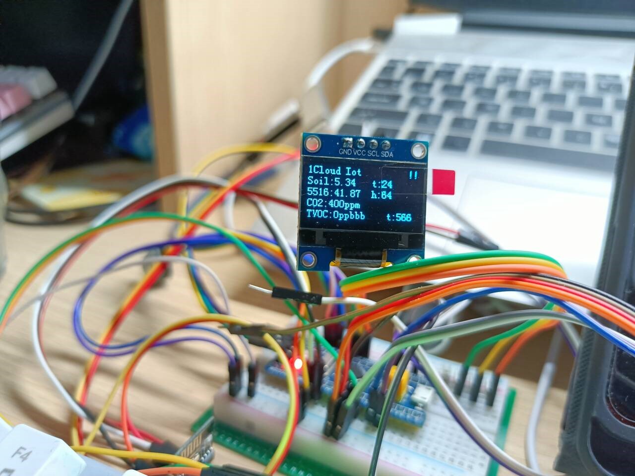
Figure 2-1: Preliminary implementation of the data acquisition section
. Actuator Processing Section: Functions implemented as follows:
Independent button control for turning irrigation, air spraying, simulated supplemental lighting, heating, ventilation, and alarm modules on and off.
On April 16, 2024,
the Alibaba Cloud IoT platform was set up, and the hardware was connected to the IoT platform.
A product was created: Smart Agriculture Test. Under this product, a device was created: mqtt-stm32. A physical model was created as shown in Figure 2-2, and a web interface was built using value-added services.

Figure 2-2: MQTT-STM32 physical model. Initial design of the solar charging circuit
on April 17, 2024.
The voltage reached 21.1V, roughly verifying the feasibility of the solution. Note the dimensions of the PCB battery box; this was not considered during verification, so the battery box could not be mounted on the PCB.
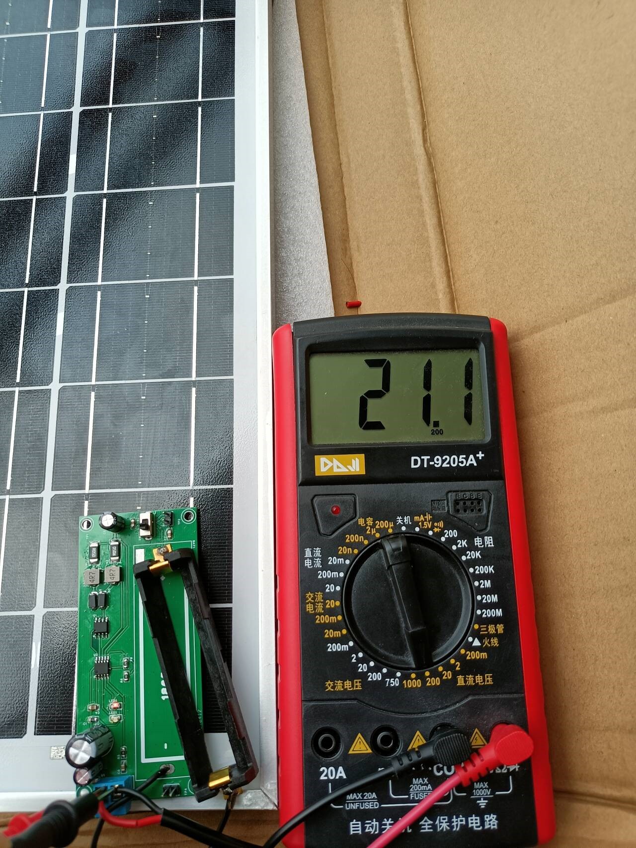
Figure 2-4: Initial design of the solar charging circuit . Schematic diagram and PCB fabrication verification
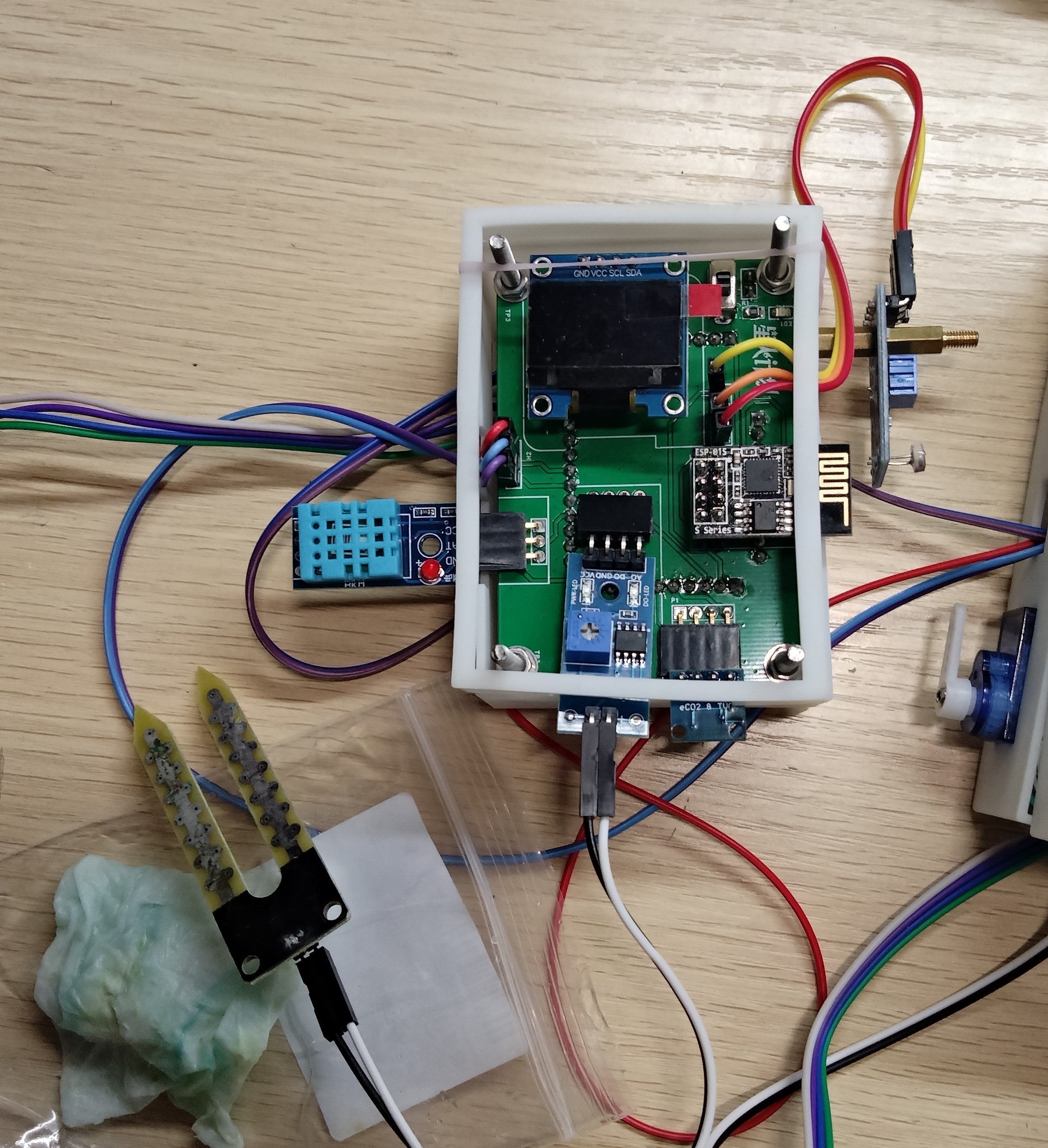
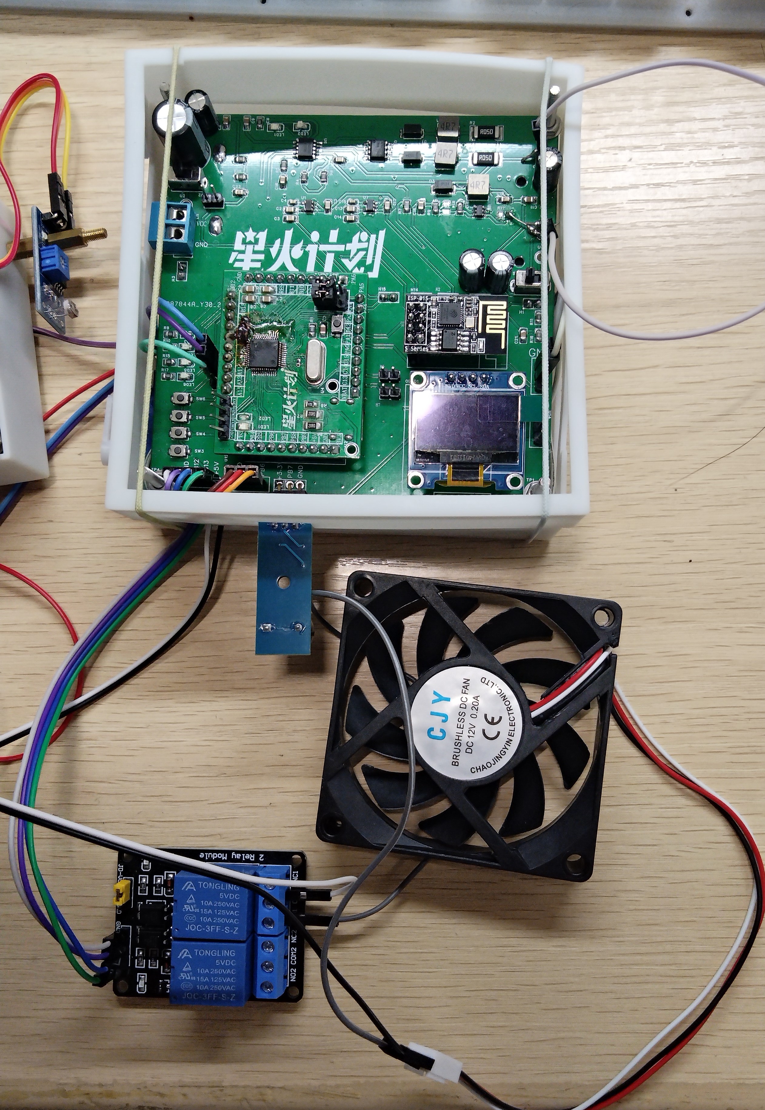
on April 18, 2024. Preliminary physical prototype: Figure 2-5: Solar charging and control actuator section. Figure 2-6: Data acquisition section physical prototype. Three days away from April 27 to May 5, 2024 , began refining the project and writing the report. Current results are as follows: May 10, 2024: The project is nearing completion. Chapter 3: Design Principles 3.1 Overall System Design Architecture Based on the functional requirements of the Smart Farmland Remote Data Acquisition and Management System, this system designs an environmental data acquisition system. Various sensors, such as those for air temperature and humidity, soil moisture, light intensity, and carbon dioxide, are deployed at the perception layer. The collected data is transmitted to the application layer via wireless WIFI technology and the MQTT protocol module at the network layer. The application layer, located on the Alibaba Cloud IoT cloud platform's web interface, displays the detected farmland environmental data and the status of the control system's actuators, generating historical data trend charts for easy observation and reference.


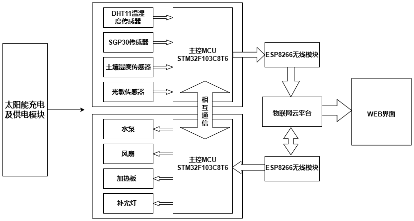
3.2 System Hardware Framework
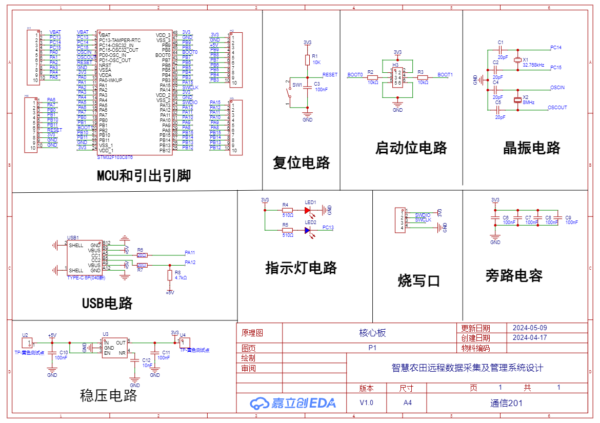
3.3 Schematic Diagram
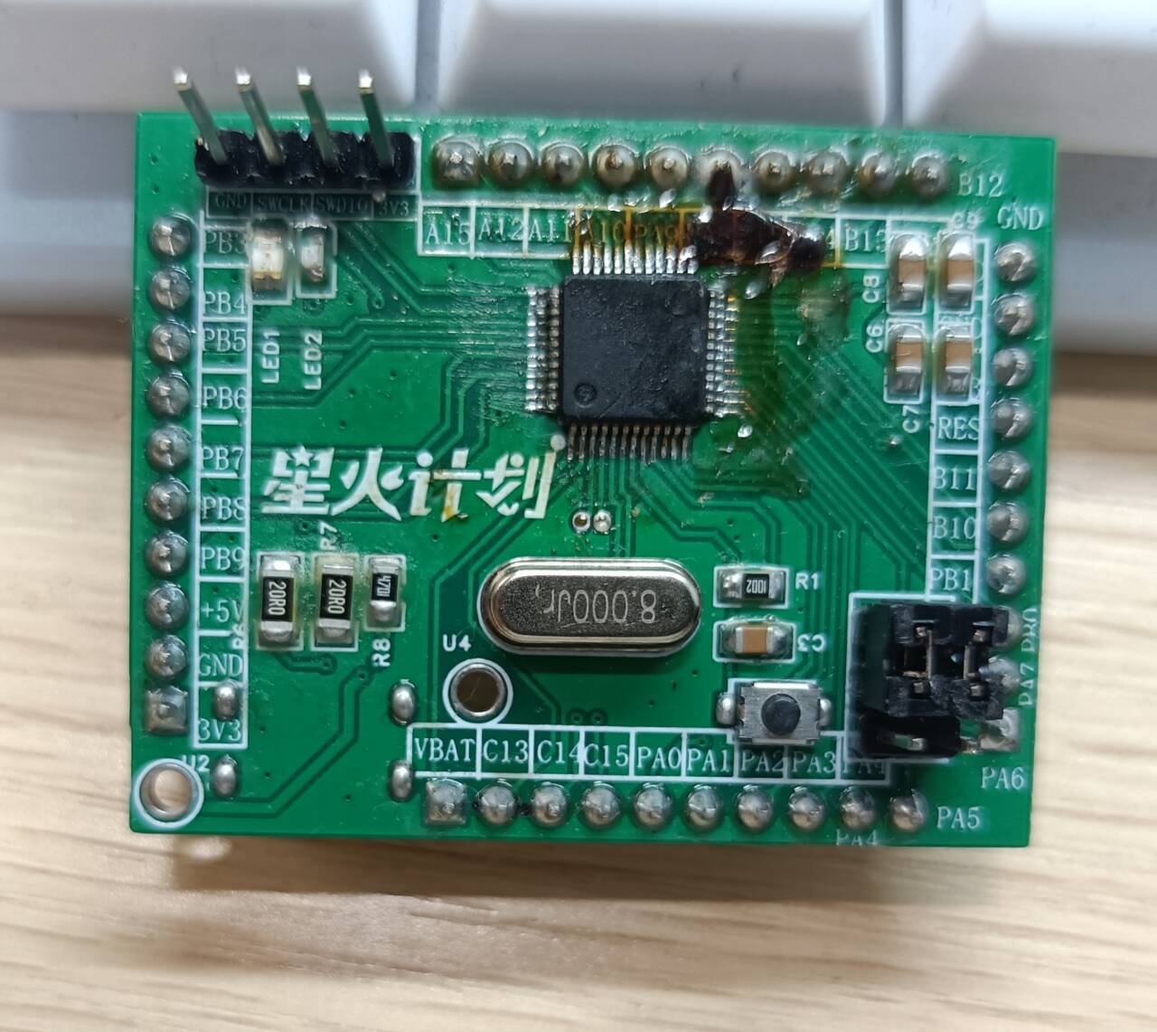
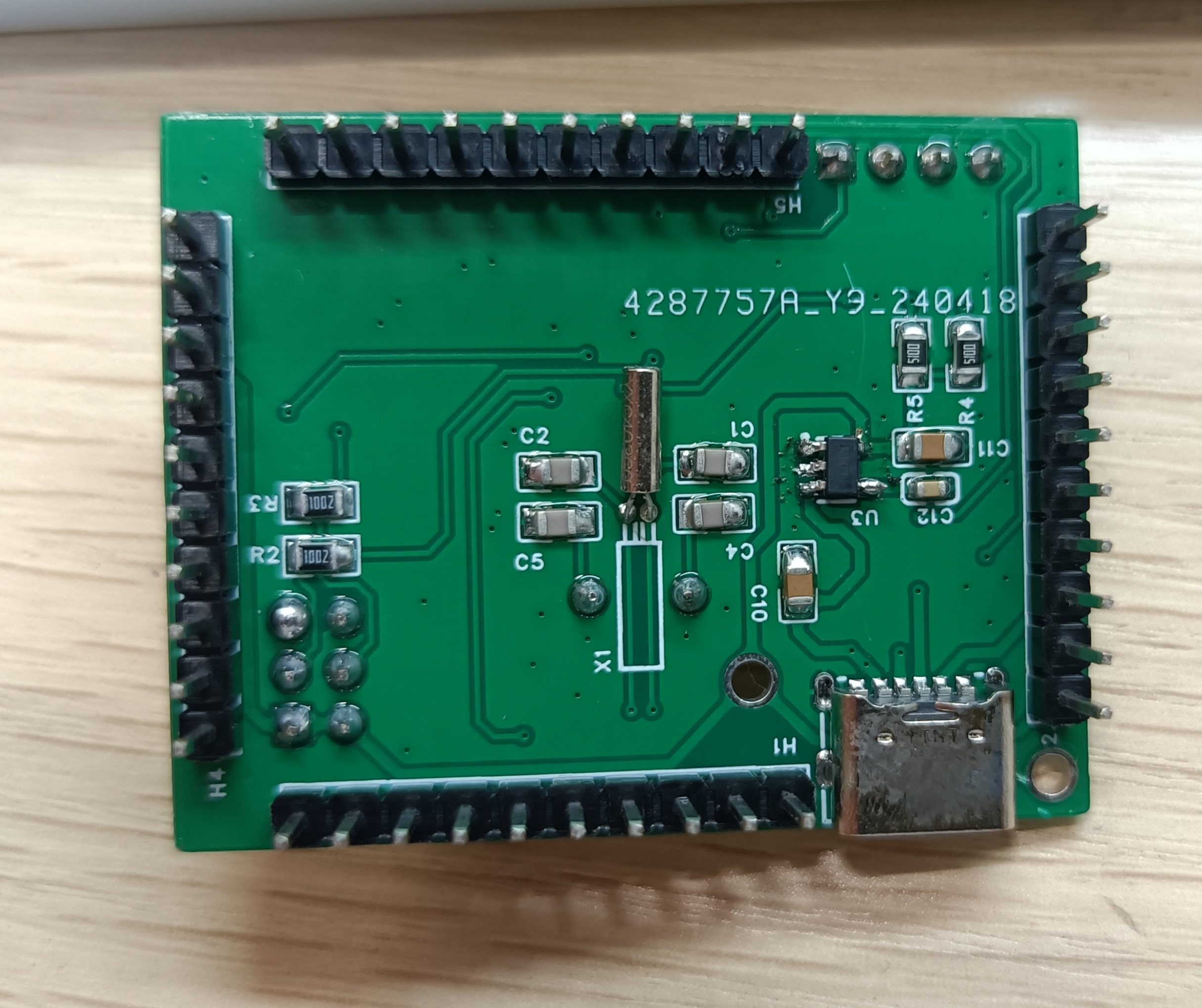
(1) Design of the core board
STM32F103C8T6 microcontroller minimum system. Draw a minimum system according to your own ideas.
I soldered two pieces. This piece was not soldered well and had a cold solder joint. I was not willing to give up and soldered it three times to make it work.
(2) Hardware schematic diagram of data acquisition part
The data acquisition part mainly consists of five modules: microprocessor module, various sensor modules, WIFI wireless communication module, USRT serial communication module and power supply module. The schematic diagram of the data acquisition part is shown in the figure below.
In the design of the data acquisition part, the STM32 microcontroller is the core part, responsible for analyzing and collecting data from various sensor devices in the farmland (greenhouse) remote data acquisition and management system, and uploading it to the cloud platform through the WIFI module and communicating with the WIFI module and actuator processing part through the UART serial communication module. Each sensor module makes a selection based on the environmental data to be collected, and also considers the way the microprocessor module reads the data. The WIFI module is the bridge for communication with the cloud platform, and it completes the uploading of environmental data. UART serial communication is used to send data information to the actuator processing section and WIFI module via serial port.

(3) Hardware schematic diagram of actuator processing section and power supply section
The actuator processing section mainly consists of five modules: microprocessor module, various actuator device modules, UART serial communication module, WIFI wireless communication module and power supply module. The schematic diagram of actuator processing section is shown below.
In the design of actuator processing section, STM323 microcontroller is the core part, responsible for detecting the working status of each control module and the battery level and uploading it to the cloud platform through WIFI wireless communication module, receiving information sent from data acquisition section via UART serial communication and processing it. Each actuator module is responsible for executing the microcontroller's instructions, such as watering, supplemental lighting, ventilation, heating and other functions. UART serial communication is used to receive data information from data acquisition section. WIFI wireless communication is the bridge with cloud platform, uploading the status of controller device to cloud platform and receiving control instructions related to cloud platform.
The power supply section is composed of three main parts, namely the photovoltaic solar panel BUCK step-down circuit, the relay and other 5V equipment BOOST boost circuit, and the microcontroller and other 3.3V equipment LDO step-down circuit. As shown in the figure below.

Note:
(1) When drawing the PCB, the core board is drawn by yourself. If you buy the STM32 minimum system finished product directly, remember to change the PCB of the main control microprocessor.
(2) The fan power supply is 12V. You also need to add a boost module and combine it with the relay to power the fan.
Assemble the finished product
Chapter 4: Terminal cloud platform system design
Define the basic information of the product on the Alibaba Cloud IoT platform. Product name: Smart Farmland Remote Acquisition and Management System. And establish two node devices in the product directory, namely the STM32_WIFI_1 device for data transmission and the STM32_WIFI_2 device for operating the actuator device.
The next step is to define the object models in the product. The object models for data acquisition and actuators involve air temperature (temp), air humidity (humi), relative light intensity (LightLux), soil relative humidity (soilHumidity), carbon dioxide (CO2), volatile organic compound concentration (HCHO), watering (SGP30), heating plate status switch (hot), fan status switch (fan), simulated supplementary lighting status (led1), air spray status light 2 (led2), and work light status (led). See the table below for specific types.

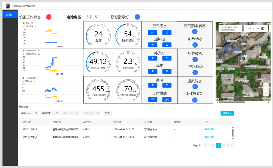
The web interface, starting from the top left, displays the following: device operating status (red indicates abnormal operation, green indicates normal operation); real-time battery status; alarm function (blue indicates normal operation, red indicates alarm); three real-time voltage curves to display environmental data changes over the past three hours; six dashboards to display real-time data; system operating mode and on/off settings for the five actuator functions; actuator device operating status (blue indicates off, yellow indicates on); additional device location map and device management functions.
Chapter 5: Core Code Description
The system development utilizes the HAL library of the STM32CubeMX development software, combined with KEIL5 for writing and compiling the system code. ST-Link is used for code burning, and Ai-Thinker serial port assistant software is used for physical debugging.
The software system design of this system mainly includes the software system design of the hardware modules and the design of the terminal software Web interface, covering the entire system's data acquisition, transmission, monitoring, and operation processes. Its design flow is shown in Figure 5-1.
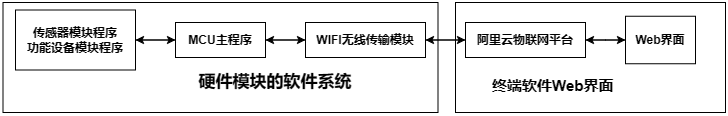
Figure 5-1 Software System Design Block Diagram of the Hardware Part
Below, I will mainly introduce the software system design of the hardware modules. The hardware part of the smart farmland remote data acquisition and management system is controlled by a program running inside the STM32 microcontroller. STM32 microcontroller 1 acquires and processes information collected by various sensors, uploads farmland environmental data to the cloud platform, and detects whether environmental data is enabled and sends this information to STM32 microcontroller 2. Microcontroller 2 executes various actuators and also uploads the status of each actuator device to the cloud platform. The software design flow of the smart farmland remote data acquisition and management system is shown in Figure 5-2:
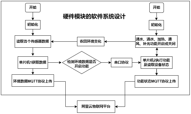
Figure 5-2: Software system design flowchart of the hardware module.
The specific design of the hardware module software system includes the configuration of timer polling, serial port 1 communication configuration between the two microcontrollers, serial port 2 communication configuration for WIFI wireless transmission, DMA multi-channel ADC configuration for reading soil moisture and light intensity, ADC configuration for detecting solar charging voltage and battery voltage, IIC configuration for reading carbon dioxide and volatile organic compound concentrations from the SGP30 sensor, GPIO configuration for reading air temperature and humidity from the DHT11 sensor, IIC communication method for OLED display of actuator status, and GPIO control logic configuration for LED supplementary lighting, relays to achieve heating and ventilation, air sprinkler, SGP30 watering, and buzzer alarm control.
The use of an STM32 microcontroller for the system's microprocessor determines the development tools used for the software design. The system's hardware software development utilizes the HAL library of the STM32CubeMX development software, combined with KEIL5 for writing and compiling the system code. ST-Link is used for code burning, and Ai-Thinker serial port assistant software is used for physical debugging. For
the wireless transmission part of the system, the lightweight publish/subscribe messaging (MQTT) protocol is used. During MCU initialization, the ESP8266-01s wireless transmission module, which uploads data, publishes and subscribes to messages with the IoT platform. Then, each time farmland environmental data is obtained, it is transmitted to the IoT cloud platform every 5 seconds via the MQTT protocol.
Chapter Six: Hardware and Software Debugging
After the hardware and software design are completed, the entire system is tested, including hardware facility testing and web terminal interface testing.
The hardware components include whether the data acquisition of farmland (greenhouse) environment is normal, whether the serial communication between the two STM32s is normal, whether the control and status recognition of the actuator device are normal, whether the WIFI wireless transmission module uploads data to the Alibaba Cloud IoT cloud platform of the computer terminal and the MQTT protocol communication is normal, and whether the photovoltaic solar cell BUCK step-down circuit, the BOOST step-up circuit of the 5V device, and the LDO step-down circuit of the 3.3V device are normal and can maintain self-sufficiency and stable operation.
The debugging of the web terminal interface of Alibaba Cloud IoT platform is as follows: mqtt.fx simulates MQTT client to publish and subscribe to messages, and the wireless transmission module ESP8266-01s publishes and subscribes to products of IoT platform through AT commands. Finally, it is verified whether the ESP8266-01s wireless transmission can successfully upload farmland data using MQTT protocol and update in real time, whether the historical trend chart can be generated normally, and whether the actuator device can display working status and be controlled in the web interface.
Chapter 7: System Physical Test Results
7.1 Implementation of System Remote Environmental Monitoring and Actuator Functions
7.1.1 Implementation of Data Acquisition Function
The modules involved in the environmental monitoring function are air temperature and humidity sensor, soil moisture sensor, light intensity sensor and SGP30 gas sensor. Each module works normally and displays environmental parameters on the cloud platform, indicating that the environmental monitoring function is operating normally. The following is the specific test process:
(1) Assemble the hardware of the data acquisition part of each module and connect it to the power supply part.
(2) Turn on the local area network wireless network, start the power supply, and check the initialization of each module through the display module of the data acquisition part.
(3) Open the Alibaba Cloud IoT platform, check the device connection status in the product, enter the device to view the object model data, you can view the real-time data of the object model, or click on each object model data to view historical data.
(4) Enter the Web interface, you can intuitively view the real-time data and historical data in the interface.
The results displayed on the Web interface are shown in Figure 7-1 below. The system uploads several environmental parameters collected from the field environment in real time. The left side of the figure shows the data changes of the six environmental parameters in the latest three hours, and the right side shows the real-time data of the six environmental parameters.
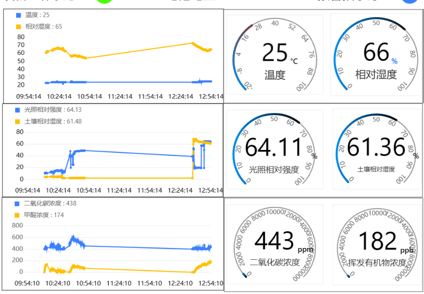
Figure 7-1 System physical test remote environmental data acquisition Web interface
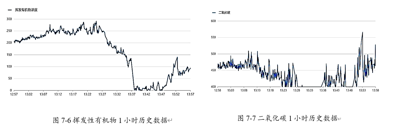
Each environmental parameter can also be viewed in a unified manner on the cloud platform. The changes in the parameter curve can be used to study the appropriate growth environment parameters for crops. As shown in Figures 7-2 to 7-7 below.
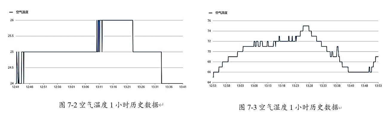

Through the test of the system, the data acquisition function of the system can operate normally. The real-time remote monitoring of the farmland (greenhouse) environment can be realized through the designed Web interface, and the environmental information necessary for crops such as air temperature, air humidity, light intensity, soil moisture, carbon dioxide concentration and volatile organic compounds can be obtained.
7.1.2 Implementation of Actuator Function
Users can implement the farmland actuator function module through the Web via the system. This simulation uses actuator servo motors, relays, and supplementary lights. Each actuator works normally under the control of the microcontroller, and the working status of the device is displayed on the Web interface of the cloud platform, indicating that the control function is operating normally. The specific test process is as follows:
(1) Assemble the hardware of the actuator processing part and connect it to the power supply part.
(2) Turn on the local area network wireless network, start the power supply, and check the working status of the actuator through the display module of the actuator processing part.
(3) Open the Alibaba Cloud IoT platform, check the device connection status in the product, enter the device to view the object model data, and you can see the real-time status of the object model, or click on each object model data to view the historical status.
(4) Enter the Web interface, and you can intuitively view the working status of the actuator device and the battery voltage in the designed interface.
The control and status physical test display interface of the system actuator function is shown in Figure 7-8 below. Blue indicates off, and yellow indicates on.
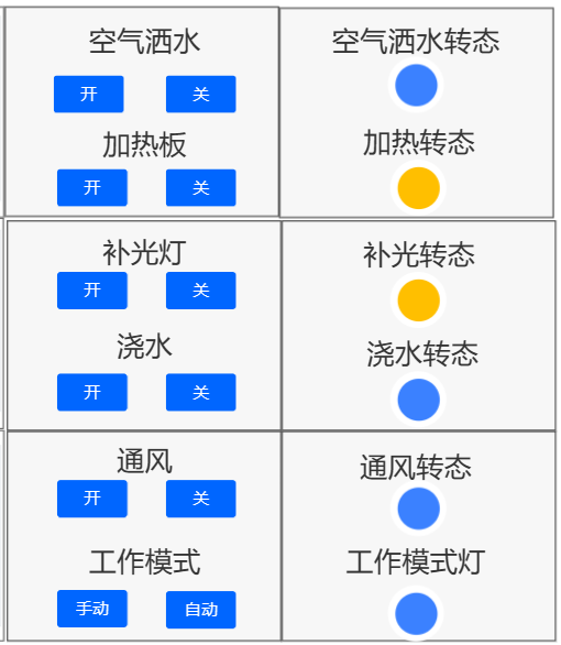
Figure 7-8 shows the control and status of the actuator function,
and the battery voltage and overall operating status of the actuator section are shown in Figure 7-9. Red indicates abnormal operation, and green indicates normal operation; the current state is normal. The battery voltage is 3.7V, providing normal power. During extreme environmental changes, the system's alarm function will also be activated; red indicates alarm enabled, and blue indicates alarm disabled.

Figure 7-9 shows the battery voltage and overall operating status of the actuator section
. The system can set the actuator's control data stream through a Web interface. The microcontroller decodes the received data and then controls the switching of each actuator. After the actuator completes its corresponding operation, its status is uploaded to the Web interface for display.
When executing control commands through the Web interface, there are network transmission issues, resulting in a 1-5 second time delay during the entire actuator function implementation. However, this delay will not affect the normal operation of the actuator.
7.1.3 Implementation of Automatic Irrigation, Temperature and Light Adjustment Functions:
Data acquisition and execution are communicated via UART serial port to realize automatic irrigation, temperature and light adjustment functions. The actual system test web interface is shown in Figure 7-10. In manual control mode, the working mode indicator is bright yellow, indicating that the mode is enabled. When the air spray is turned on in the web interface, the supplementary light indicator turns yellow and does not automatically turn off (the web interface does not turn blue, and the hardware supplementary light is on). In automatic control mode, when the light is directed at the light sensor, the supplementary light indicator automatically turns blue, and the hardware supplementary light turns off.
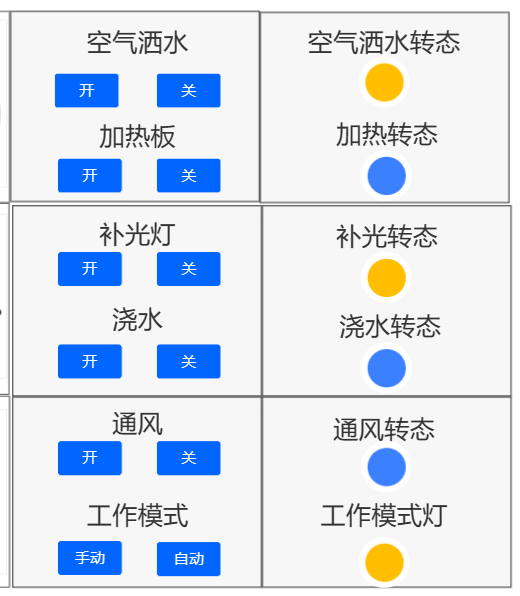
Figure 7-10 shows the actual system test web interface
functionality and video viewing effect .
Chapter 8: Summary and Outlook
. The following are the main problems:
The addition of video monitoring equipment; the design of wireless video signal monitoring with cameras to monitor the growth of crops. A camera module has been purchased, but the current communication protocol of the system cannot transmit video signals, and the learning is insufficient to add a camera. If there is an opportunity to add a camera later, that will be discussed.
Secondly, I would like to thank the platform for its support. Thank you!!!
Lastly, this is the first generation version, and many things were new to me. There were many oversights in the design, such as the need for 12V to power the fan, the messy DuPont wiring, and the unreasonable sensor placement. I considered many solutions, such as integrating some modules onto the board, like relays, a 2V boost converter, the core board, and the WiFi module, or making it a single board. Although this project isn't perfect or outstanding, it has become a milestone in proving my abilities. Perhaps one day in the future, when I look back at this project, I will have the skills to improve it and design it better.
I say the future is promising, and, sir, I really want to improve.
May 17, 2024


 京公网安备 11010802033920号

 RS0106R120BE7338


