
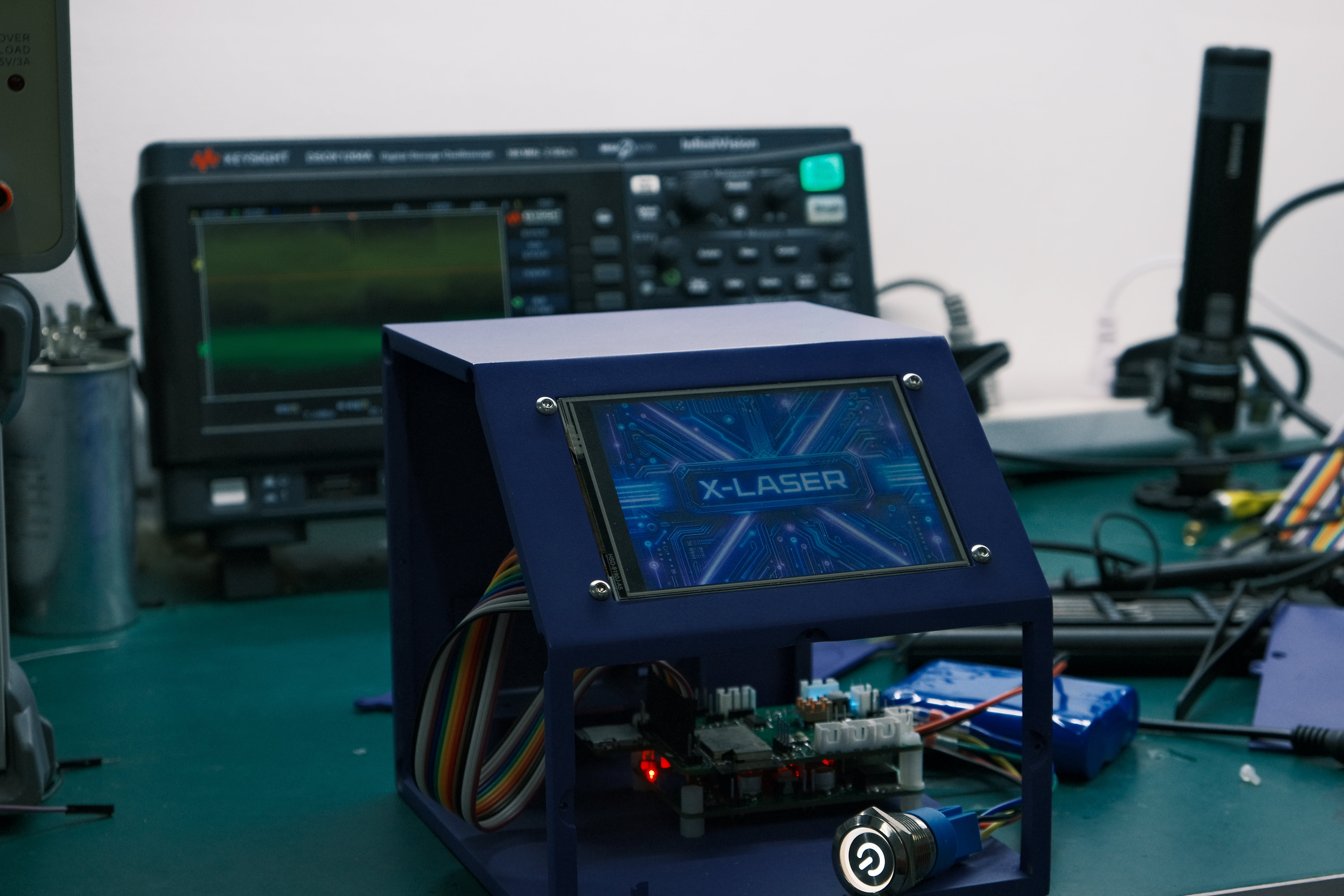
X-Laser is a small vector laser projector we developed, designed to bring users a brand-new laser experience—easily creating personalized projections for various scenarios. X-Laser bridges the gap between virtual and reality with lasers, providing innovative ideas for image presentation, artistic creation, and car navigation.
This project is based on laser galvanometer technology, changing the laser emission direction by shifting the galvanometer, and utilizing the persistence of vision to project vector animations. Users can save laser animations (files with the .ild extension) to a MicroSD card and select "Example" to play them after launching the projector; alternatively, they can select "Draw Now" to draw their desired laser animation on the LCD screen for projection!
This repository contains open-source materials including
circuit design schematics and PCBs for two core boards,
MCU firmware source code, screen UI project source files, and
shell design structure project source files.
GitHub repository link: https://github.com/zrrraa/X-Laser
LCSC project link: https://oshwhub.com/small-horn-projection-team/x-laser
Bilibili demo video: https://www.bilibili.com/video/BV12m411z7Wr/?vd_source=1d0c07486a3bd3b0adb8ac548bf6453e
1. Project Description
1.1 Project File Structure
1.1.1 The Hardware
folder contains the core circuit board schematics and PCBs for X-Laser, providing source files in LCSC EDA Professional Edition format and Garber format photoplot files.
There are two boards in total:
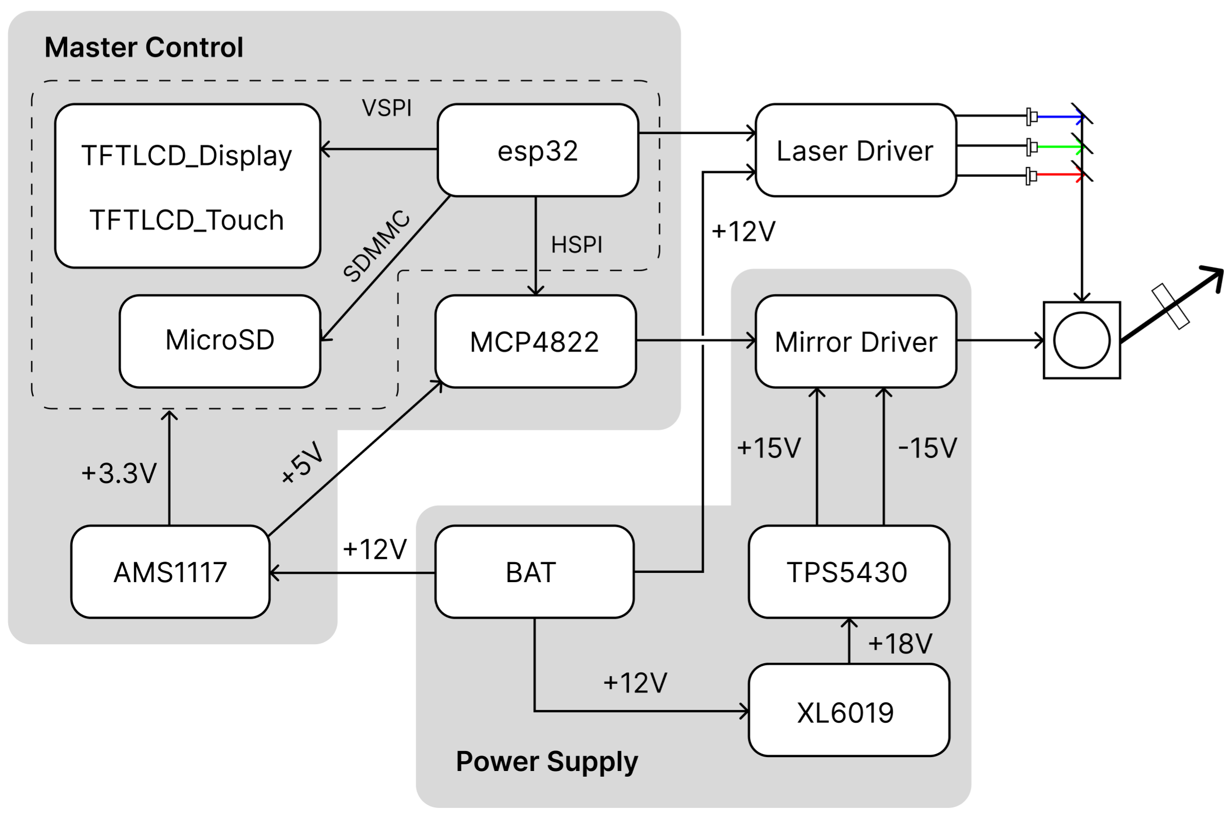
The Master Control board: This is the core control PCB for the X-Laser, using an ESP32 microcontroller. Its peripheral circuitry integrates drivers for a DAC, MicroSD card, and TFT LCD. The TFT LCD is connected to the Master Control board via DuPont wires. The galvanometer motor driver board and laser driver board are connected to the Master Control board via XH wires.
The Power Supply board: This board handles the level conversion between +12V, +18V, +15V, and -15V. The Power Supply board and Master Control board are connected and fixed together via pin headers, sockets, and copper pillars. The pin headers and sockets provide +15V and -15V to the Master Control board as power for the operational amplifiers in the differential circuit. 1.1.2 Firmware
The firmware source code for the Master Control board is provided in the Firmware folder. The esp32/build folder contains pre-compiled firmware that can be directly burned. The main contents of the source code are as follows:
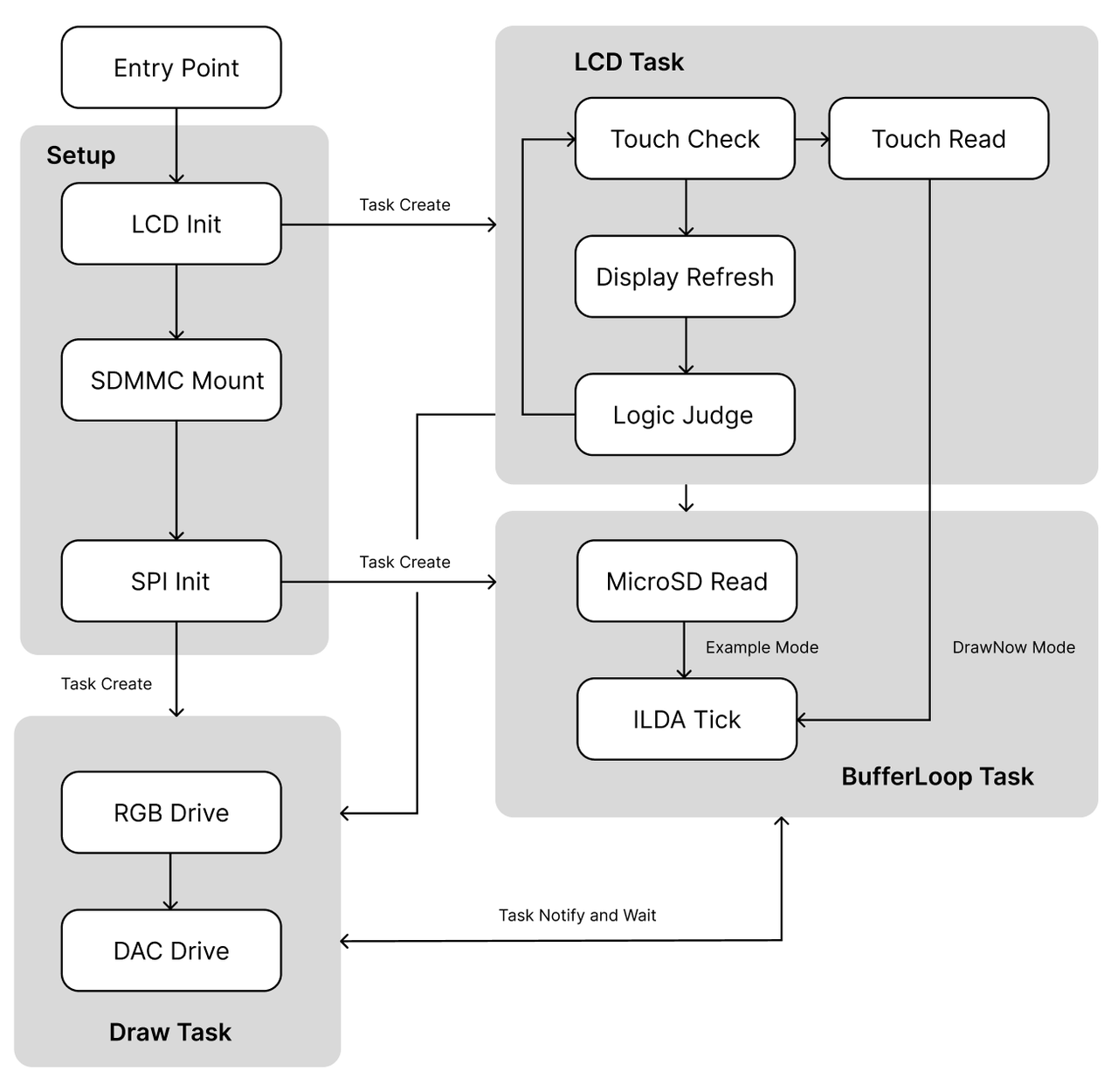
ESP-IDF FreeRTOS multi-tasking loop, containing three tasks: reading and caching from the SD card to RAM, SPI driving the DAC to output data from RAM, and TFTLCD UI interaction and control. This is mainly contained in the file esp32/src/CoreLoop.cpp.
The TFTLCD UI files and SquareLine Studio project source files implement user selection and hand-drawn laser animation playback using the LVGL and TFT_eSPI libraries. The SquareLine Studio project is in the UI folder; lvgl events and the TFTLCD driver are in esp32/lib and the file esp32/src/MyTFTLCD.cpp.
The SDMMC driver and HSPI/VSPI drivers are mainly contained in esp32/src/SPIRenderer.cpp and esp32/src/SDCard.cpp.
ILDA file-related functions are mainly contained in esp32/src/ILDAFile.cpp.
The code is structured using Platform.io in VS Code. Open the project with Platform.io and connect the CH340 to the TX and RX pins to burn the firmware. 1.1.3 The 3D Model
folder contains the Fusion source project files for the X-Laser structural design and model files directly usable for 3D printing.
1.1.4 The Docs folder
contains relevant reference documents, including ILDA file documentation, playable laser animation files, datasheets for important chips, and parameters and bills of materials for peripherals used in this project.
2. Hardware Architecture Description
Regarding the structural design,
the X-Laser's structural design includes a frame with only top and bottom panels and four panels, secured with bolts, nuts, and screws.

The sides contain structures for fixing the laser galvanometer driver board, while the main frame includes structures for fixing the galvanometer motor and RGB laser module.

The logo side includes the power switch mounting threads and a slot for the SD card. The side fixing the laser galvanometer driver board features a continuous slot design for aesthetics and heat dissipation. The sloping surface of the main frame has apertures for fixing the TFTLCD screen. Two PCBs are fixed vertically on the back using copper pillars and pin headers. If a mounting bracket is needed, a bracket with a magnetic ring can be purchased and placed at the bottom.
Regarding the firmware source code,
this project's firmware is based on ESP-Arduino and calls the ESP-IDF FreeRTOS API, effectively synchronizing the operation of multiple peripherals. The main program flow is shown in the diagram below.
The X-Laser uses an ESP32 as the main control MCU, driving the DAC chip to control the galvanometer motor via HSPI; the RGB laser diode module uses MCU control signals to determine seven colors; the human-machine interface uses a TFTLCD touchscreen, driven by VSPI; and the MicroSD card uses SDMMC for communication.
Regarding the management of multiple peripherals, all three peripherals (considering the LCD display and touch as one) need to run continuously. In the initial design, two SPI paths were used to control all peripherals, but the results were unsatisfactory. Idle tasks were prone to crashing during SPI time-division multiplexing, and the RTOS's blocking and notification mechanisms could not perfectly stabilize them, and the projection frame rate was limited. Ultimately, SDMMC was chosen to read the MicroSD card.
Regarding the notification and blocking between the caching and projection tasks, the approach is that all upper-level logic only controls the caching and does not directly affect projection; the caching is self-blocking when it is full; projection notifies the caching after execution, as projection depends on the caching and cannot allow empty projection frames.
When it is necessary to clear laser animation data in RAM, such as in the DrawNow mode's Clear function, the approach is similar to stack operations: only the pointer is moved back to the memory starting point, and variables such as the total number of frames are cleared, without actively clearing the animation data.
The LCD's UI is designed based on SquareLine Studio.

Since the LVGL library exported by SquareLine cannot call custom functions, the current method to use the button callbacks in lv_events.c is to define a variable in this file as the button state, declare this variable as an external variable in a custom header file, and then check this variable in the LCD Task, allowing button events to be written in custom function files.
Regarding power management and the mirror driver...
The X-Laser is powered by a 12V lithium battery with an XH package; pay attention to the positive and negative orientation. It can be fitted with a lithium battery that has a DC charging port; the charging port is glued to the round hole on the side. The 12V is boosted to 18V on the power board, then stepped down to ±15V (if it is only boosted to +15V, it cannot be stepped down to -15V). The 12V powers the laser driver board and is also connected to the main control board via pin headers and sockets. On the main control board, it is stepped down to 5V and 3.3V to power the MCU and onboard peripherals. The ±15V is connected to the main control board via pin headers and sockets to power the differential circuit controlling the galvanometer motor driver board.
The MCU calculates the proportional mapping relationship based on the projection point position and outputs 1.024V~3.072V through the DAC. After bias amplification, this is converted to -2.048V~+2.048V and input to the galvanometer driver board to drive the galvanometer deflection.
Regarding the high-current drive issue
in freehand mode, the LCD reads the touch points and the current Colorwheel parameters, stores them in a structure variable, and notifies the Draw Task to loop through the stored touch point projections. When the number of stored points is small, the mirror current will be very high, causing the inductor solder in the 12V to 18V circuit to melt and explode. In the final version of the circuit, a large 330uH inductor was used, and the number of points was checked in the firmware source code, reducing the mirror frequency when the number of points was small.
Similarly, excessive current can cause the self-locking switch on the main control board to burn out. Since this self-locking switch was only used during testing, it was replaced with a normally closed connection of a header and jumper cap during subsequent soldering, without any modifications to the PCB or schematic.
In the initial version of the circuit, we tried to directly drive the laser diode with MOSFETs, which caused the laser diodes to operate abnormally, burning out many of them; at the same time, the MOSFETs also frequently burned out because they could not withstand the high current. Later, we changed to using the original laser driver board for driving, with the MOSFETs only used as switching circuits.
Regarding compilation, programming, and booting
the chip, at least 2MB of Flash memory is required. When compiling in Platform.io, a partition table needs to be added; refer to the official partition table example. The partition table for this project is located in Firmware/esp32/huge_app.csv. The MicroSD's DAT0 pin is connected to ESP32's IO2, which will force it high. When programming the firmware, a jumper cap needs to be inserted into the H31 header to pull this pin low, putting the ESP32 into download mode. In X-Laser, we chose the N8R8 module chip; in reality, this much RAM is not needed because dynamic read/write is used.
ESP32's power-on auto-boot requires the BOOT to be pulled high. Although the BOOT is pulled high by default, in the final design, it was found during actual testing that the program would not boot without manual pull-up. Therefore, a 1K resistor was used to manually pull up the BOOT in the final circuit.
Create a new folder named ILDA on the MicroSD card and put the laser animation files in it. After booting, the read laser animation files can be seen in the screen's scroller. Animation file names must be shorter than 15 characters; otherwise, they will not display completely and will not play correctly. There are frequency limitations on touchscreen refresh and touch point reading
in DrawNow mode
, so drawing "slowly" is more effective. When drawing laser animations, the laser diodes need to be turned off between two consecutive curves, waiting for the galvanometer to shift before turning them back on; otherwise, the entire pattern will be closed. These considerations have been taken into account and path planning has been implemented in the ILDA file. In DrawNow mode, turning off the laser diodes and waiting for the galvanometer to shift before turning them back on still creates a visual persistence effect. Adding a small delay improves this; 5ms was optimal in testing, while a longer delay can cause animation flickering.
...
else
{
digitalWrite(PIN_NUM_LASER_R, HIGH);
digitalWrite(PIN_NUM_LASER_G, HIGH);
digitalWrite(PIN_NUM_LASER_B, HIGH);
delay(5); // Ensure the curve is broken
}
// DAC output refresh
digitalWrite(PIN_NUM_LDAC, LOW);
digitalWrite(PIN_NUM_LDAC, HIGH);
# 3. Acknowledgements to
YouTuber atomic14's project, which greatly helped us learn the structure analysis of ILDA files and the overall code architecture.
[https://github.com/atomic14/esp32-laser-show/tree/main](https://github.com/atomic14/esp32-laser-show/tree/main)
The excellent structural design and code ideas in the bbLaser project by uploader CoreBilibili greatly helped the design of X-Laser. Thank you very much.
[https://github.com/RealCorebb/bbLaser](https://github.com/RealCorebb/bbLaser)
kvdz's articles on positive and negative power supplies are very detailed and provided great help when designing the positive and negative power supply circuits in our power board.
[https://blog.csdn.net/kvdz_taobao_com/article/details/103510539](https://blog.csdn.net/kvdz_taobao_com/article/details/103510539)
Pieski provided us with a lot of guidance on circuit debugging, and we would like to express our gratitude.
Zhihui's project has a very complete open-source architecture and is of great reference value, providing us with a good learning path for our first attempt at open source.
[https://github.com/peng-zhihui/HelloWord-Keyboard/tree/main](https://github.com/peng-zhihui/HelloWord-Keyboard/tree/main)


 京公网安备 11010802033920号

 SG2540


