I. Introduction
What is PCI-E?
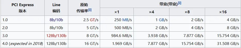
In short, PCI-E is a computer internal interconnect bus standard proposed by Intel in 2001 to replace the previous PCI and AGP. Its characteristics include serial operation (previous ISA, PCI, AGP, etc., were parallel) and support for 1 to 32 lanes (however, the most common and longest is the x16 commonly used on graphics cards), with speeds shown in the table below.
Since PCI-E transmits differential signals, it's necessary to explain the definition of differential lines:
Comparing phase signals and single-ended signals: Traditional single-ended signals are transmitted through the potential difference relative to ground, requiring only one ground wire. Transmitting multiple signals requires only the corresponding number of signal lines. Differential signals, however, use a common ground wire (potential 0). Transmitting one signal requires two signal lines: one with a positive voltage relative to ground (positive potential) and the other with a negative voltage (negative potential), both with the same absolute value (180-degree phase difference). The potential difference between the two signal lines is used to transmit the signal, but two signals are transmitted. For example, if one signal line is 3.3V, the other is -3.3V, and the ground wire is 0V. This seemingly wasteful transmission method actually has many advantages: First, because the ground wire is controllable, the voltage drop caused by wire length doesn't lead to ground wire differences, thus reducing transmission voltage and power consumption (early AGP 2X operated at up to 5V, while current PCI-E is below 1.5V); Second, because electromagnetic interference has almost the same effect on both signal lines of a differential signal, even with interference, the higher potential remains higher than the lower potential, whereas a single-ended signal might have its low potential turned into a high potential due to interference, leading to transmission errors. Therefore, differential signals have strong anti-interference capabilities. Currently, most high-speed serial interfaces use differential signals, such as USB 3.0/3.1, PCI-E, HDMI, and Ethernet.
II. Interface Definitions
1. PCI-E
Slots
: There are four interface sizes. For each interface, pins 1 to 11 are identical; the remaining pins are differential data lines and clock data lines. The corresponding PCIe size varies depending on the number of differential data lines and clock data lines

. Pin Function Definitions

2. M.2 Interface: The
M.2 interface has two bus types: SATA and PCIe. The protocols are AHCI/NVME (Non-Volatile Memory Express), a logical device interface specification.

Mechanical Structure:
The M.2 connector uses the notch position of the pins to indicate the key. This concept is used to indicate the interface/protocol supported by the module. Current specifications define five key positions: A, B, E, F, and M. Among these, B and M are the most common.
Typical Applications
: A-Key: Primarily used for wireless connections such as WiFi, Bluetooth, NFC, and Wi-Fi. Card types include 1630, 2230, and 3030.
B-Key: Primarily used for WWAN, GNSS, and SSDs. Card types include 3042, 2230, 2242, 2260, 2280, and 22110.
E-Key: Primarily used for wireless connectivity such as WiFi, Bluetooth, NFC, and GNSS. Card types include 1630, 2230, and 3030.
M-Key: Primarily used in host interfaces supporting PCIe or SATA protocols, typically SSDs.
Notably, M.2 connectors have three socket types (Socket 1, 2, and 3). Since Socket 1 is entirely soldered and only compatible with 1216, 2226, and 3026 sizes, common M.2 device connectors are mostly Socket 2 and Socket 3.
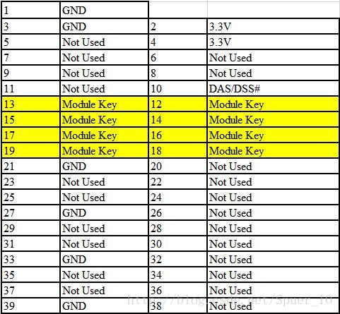
B-Key modules have pin notches located at positions 12-19, providing support for PCIe x2, SATA, USB 3.0, I2C, and HSIC.
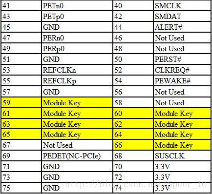
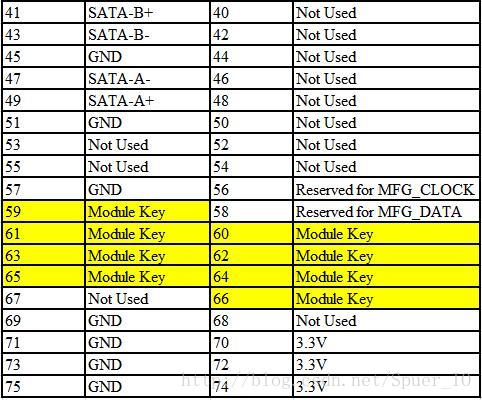
M-Key modules have pin notches located at positions 59-66, providing support for PCIe x4, SATA, and SMBus.
M.2 SSDs are almost always "B & M" key, meaning they have two notches. Configurations supporting SATA or PCIe x2 are called "Socket 2," and configurations supporting PCIe x4 are called "Socket 3."
Pin function definitions:
M.2 PCIe SSDs are M-Key;

SATA SSDs include B-Key & M-Key.
III. Design Considerations
: 1. Impedance Control:
The PCIe specification gives a differential impedance of 100Ω and a single-ended impedance of 50Ω. However, you may have seen descriptions like: "
PCI Express link traces must maintain 100Ω differential / 60Ω single-ended impedance for 4-layer or 6-layer boards; and 85Ω differential / 55Ω single-ended impedance for 8-layer or 10-layer boards."
The explanation is as follows:
the more layers a circuit board has, the closer the traces are to the reference plane, and the lower the impedance. Therefore, for impedance matching, the target impedance value should be reduced. Simultaneously, the density of multilayer boards increases, and the line width decreases. Smaller line widths result in higher impedance and increased transmission loss. Therefore, the more layers, the shorter the required trace length (to control transmission loss).
2. Gold Fingers and Connector Considerations:
Edge finger pads on the reference plane should be removed to meet impedance targets.
The edge portion of the finger along its entire length should be removed.
The differential pair traces of these two traces should be in the same area as the connector pins on the same layer.
To meet impedance targets, the reference plane under the edge gold finger should be removed.
Furthermore, the entire reference plane under the gold finger should be completely removed. The two signals of the differential pair should be routed on the same layer to the connector pins.
3. Other Considerations:
Differential pairs with inverting phase should meet a 3W pitch, and those with non-inverting phase should meet a 5W pitch.
The lengths of the positive and negative lines of the PCI-E differential lines must meet matching requirements, but the lengths between the differential lines do not need to be matched.
Polarity must be reversed.
PCI-E does not support LANE reversal.
High-frequency signal lines should be avoided on the reverse side of the PCB for PCI-E chips, especially PCIE signal lines; ideally, full GND copper should be used.
During PCB design, a high-frequency decoupling capacitor of approximately 0.1uF should be placed near each pair of power pins of the PCIe chip, not too far from the chip.
Vias connecting the power or GND traces of the PCIe chip should use large vias, double vias, or dual-loop power supplies.
The gold fingers of the PCIe PESET# pin signal should be designed to be approximately the same length as PRSNT1#.
Copper plating is not allowed on the gold fingers; copper must be removed from each layer.
IV. Physical Testing :
A disassembled laptop hard drive was used as a makeshift solution (currently used as an external hard drive).
The Hynix BC711 (OEM version) 512G (almost full drive)
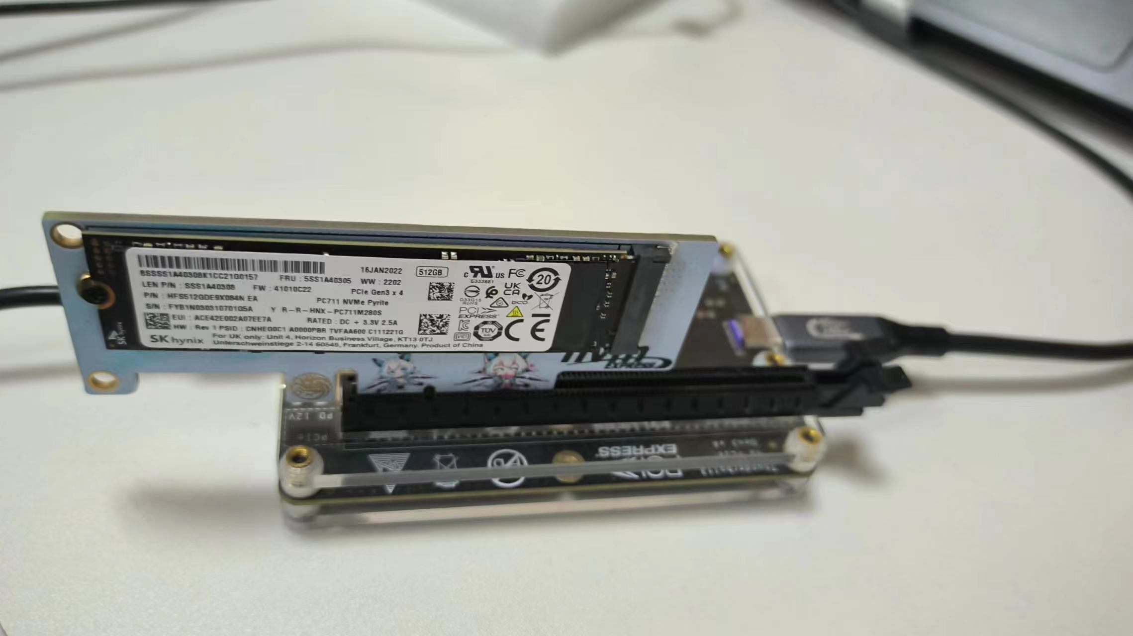
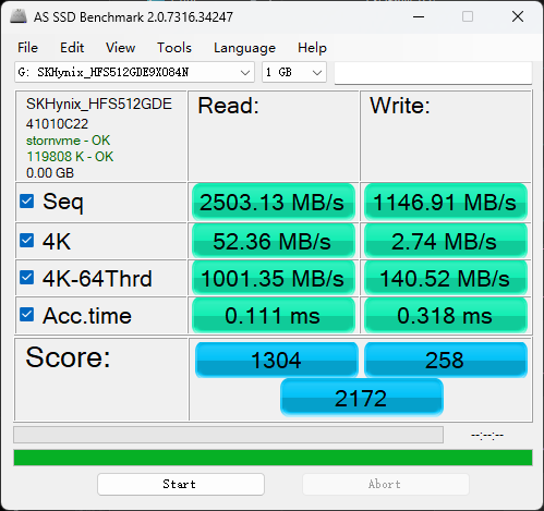
has slightly slower write speeds, but this is probably due to the full drive being used. The difference compared to the motherboard
's built-in interface is not significant. I'll try it again next time with a spare PCIe 4.0 drive (too lazy to disassemble the system) .
V. Other
1. PCI-E Stack-up and Reference Plane
Typical PC motherboards are designed with a 4-layer stack-up, while server, workstation, and mobile system motherboards often use 6 or more layers.
Expansion cards can use 4 or 6 layers. Use 0.5OZ copper-plated microstrip lines and 1OZ copper striplines.
The overall PCB thickness for expansion cards must be 0.062 inches. Mobile platform PCB thickness can be 0.062 inches or 0.050 inches.
To minimize losses and jitter budget, the most important consideration is the target impedance of the design, and maintaining sufficiently small impedance tolerances. Thicker dielectric layers and wider traces will reduce losses. Microstrip differential lines produce larger impedance variations than stripline differential lines.
Signal correspondence should avoid discontinuities in the reference plane, such as splits and gaps. When signal lines change layers, ground signal vias should be placed close to signal vias. It is recommended to use at least 1 to 3 ground signal vias for each signal pair. Also, never allow traces to cross plane splits.
2. Regarding AC coupling capacitors,
actual speed tests show little impact (perhaps because 4.0 hasn't been tested?). Since PCIe and M.2 are directly connected without going through a chip, they were simply removed.
If you want to learn more, you can refer to point 6 of the original text (M.2 interface circuit design). I won't elaborate here.
3. Regarding M.2 interfaces
, you must buy an M-Key; otherwise, you cannot connect M.2 hard drives
. M-Keys can, to some extent, replace B-Keys and have wider applicability.
For example, SATA protocol M.2 hard drives do not necessarily require B-Keys.
Also, M.2 interfaces may be more difficult to solder; desoldering wire should be helpful.
Remember to check the M.2 interface for cold solder joints, solder bridges, etc. before powering on.
(Adapted from
PCIE Bus Hardware Design Chapter:
PCIE-PCB Design Specifications!) (Recommended for saving)
PCI-E High-Speed PCB Layout and Routing Design Guide;
Simple Explanation of PCI-E Pin Definitions (Memo);
PCIx Series: "PCIe Bus Hardware Design";
M.2 Interface Circuit Design;
SSD Interface Definitions Based on M.2 Interface SATA3 and PCIe Protocols


 京公网安备 11010802033920号

 RA16XP10FB101F


