No programming required, ready to use after soldering;
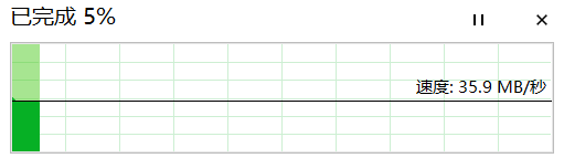
USB 2.0 protocol, connects to computer via Type-C, expands to four USB 2.0 Type-A ports;

Speed test:
USB_HUB_MINI.zip
PDF_USB_HUB_MINI.zip
Altium_USB_HUB_MINI.zip
PADS_USB_HUB_MINI.zip
BOM_USB_HUB_MINI.xlsx
97459
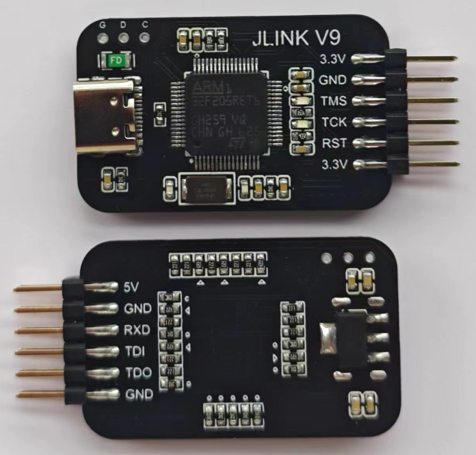
Jlink-V9-Mini
Jlink-V9-Mini
JTAG, SWD, Virtual Serial Port
Jlink-V9-Mini
(for learning purposes only)
uses an STM32F205RCT6 microcontroller, supports JTAG and SWD modes, and includes a virtual serial port.
The bootloader in the file automatically upgrades the firmware, downloading it directly to address 8000000 and running JFlash or MDK for automatic upgrades.
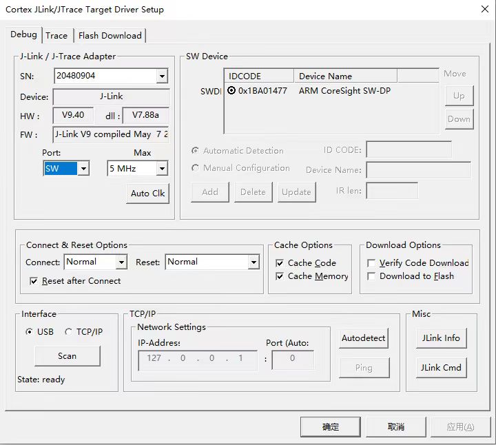
After the upgrade, JLink needs to be activated before use. The following instructions
are suitable for JlinkV9 hardware HW calculated based on SN. For example, if SN=20180904, then HW=SN/100000 (rounded down)=201, then divide by 10 and take the decimal=20.10, so the hardware HW is V9.10. If SN=20280904, then HW=SN/100000 (rounded down)=202, then divide by 10 and take the decimal=20.20, so the hardware HW is V9.20. If SN=20380904, then HW=SN/100000 (rounded down)=203, then divide by 10 and take the decimal=20.30, so the hardware HW is V9.30. If SN=20480904, then HW=SN/100000 (rounded down)=204, then divide by 10 and take the decimal=20.40, so the hardware HW is V9.40. If SN=20580904... Then HW = SN/100000 (rounded down) = 205, then divide by 10 and take the decimal = 20.50. Therefore, the hardware HW is V9.50.
Under the J-LINK command, run the following commands sequentially: Exec SetSN=XXXXXXXX ; Add SN Exec AddFeature GDB ; Add GDB Exec AddFeature RDI ; Add RDI Exec AddFeature FlashBP ; Add FlashBP Exec AddFeature FlashDL ; Add FlashDL Exec AddFeature JFlash ; Add JFlash Exec AddFeature RDDI ; Add RDDI. This
is a dedicated J-Link-V9 function addition command!
Note that currently activation can only be done with J-LINK COMMANDER V6.32B; other versions will show an error upon activation.
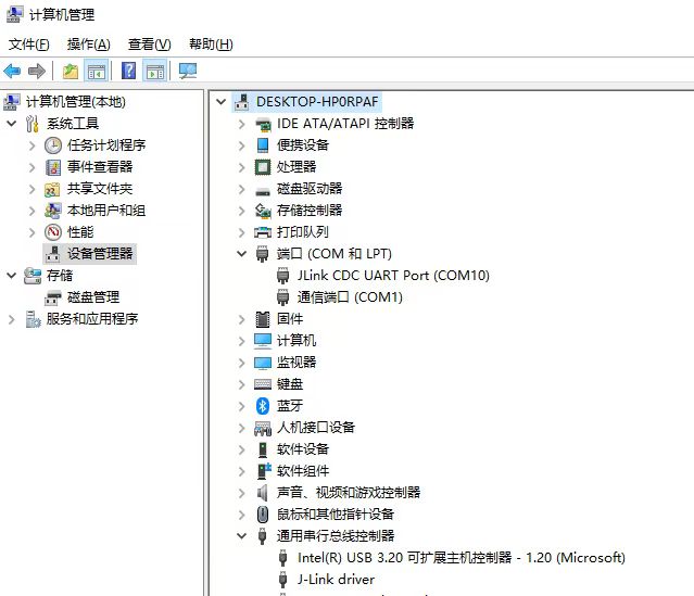
The command to open the serial port is vcom enabled. The virtual serial port and JTAG cannot be used simultaneously; the TX pin of the virtual serial port is the TDI pin.

JLink_Windows_V632b.exe
bootloader.bin
PDF_Jlink-V9-Mini.zip
Altium_Jlink-V9-Mini.zip
PADS_Jlink-V9-Mini.zip
BOM_Jlink-V9-Mini.xlsx
97460
[Unverified] BQ4050 Battery Protection Board for Smart Computers
SK231015112304 PCB Engineering
Derived from the miniBQ4050, please refer to the bq4050 Getting Started Manual: Part Two - First Power-On - Bilibili (bilibili.com) series of articles for detailed configuration procedures. This module has been verified to be unusable on Dell platforms.
PDF_[Unverified] BQ4050 Battery Protection Board for Smart Computers.zip
Altium_[Unverified] BQ4050 Battery Protection Board for Smart Computers.zip
PADS_【Unverified】BQ4050 Battery Protection Board for Smart Computers.zip
BOM_【Unverified】BQ4050 Battery Protection Board for Smart Computers.xlsx
97461
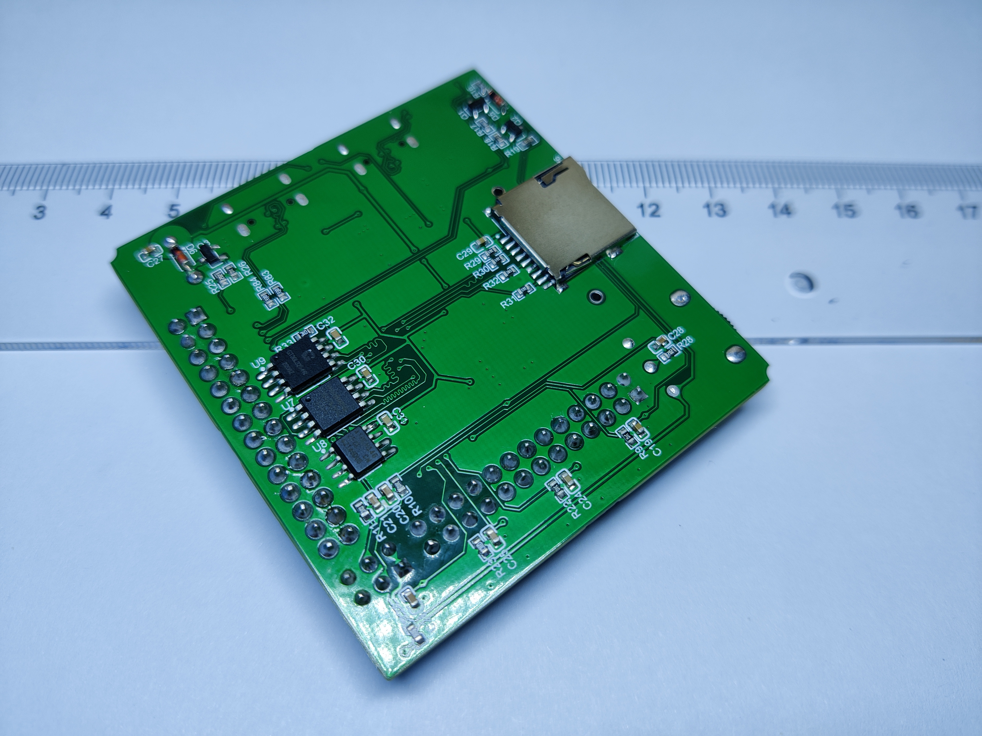
STM32F103RCT6 core board V221205
STM32F103RCT6 + Expandable Flash, ROM and Chinese character library + SD Card with automatic download + Indicator light with wake-up button + Gear potentiometer + 2 buttons + 1 buzzer.
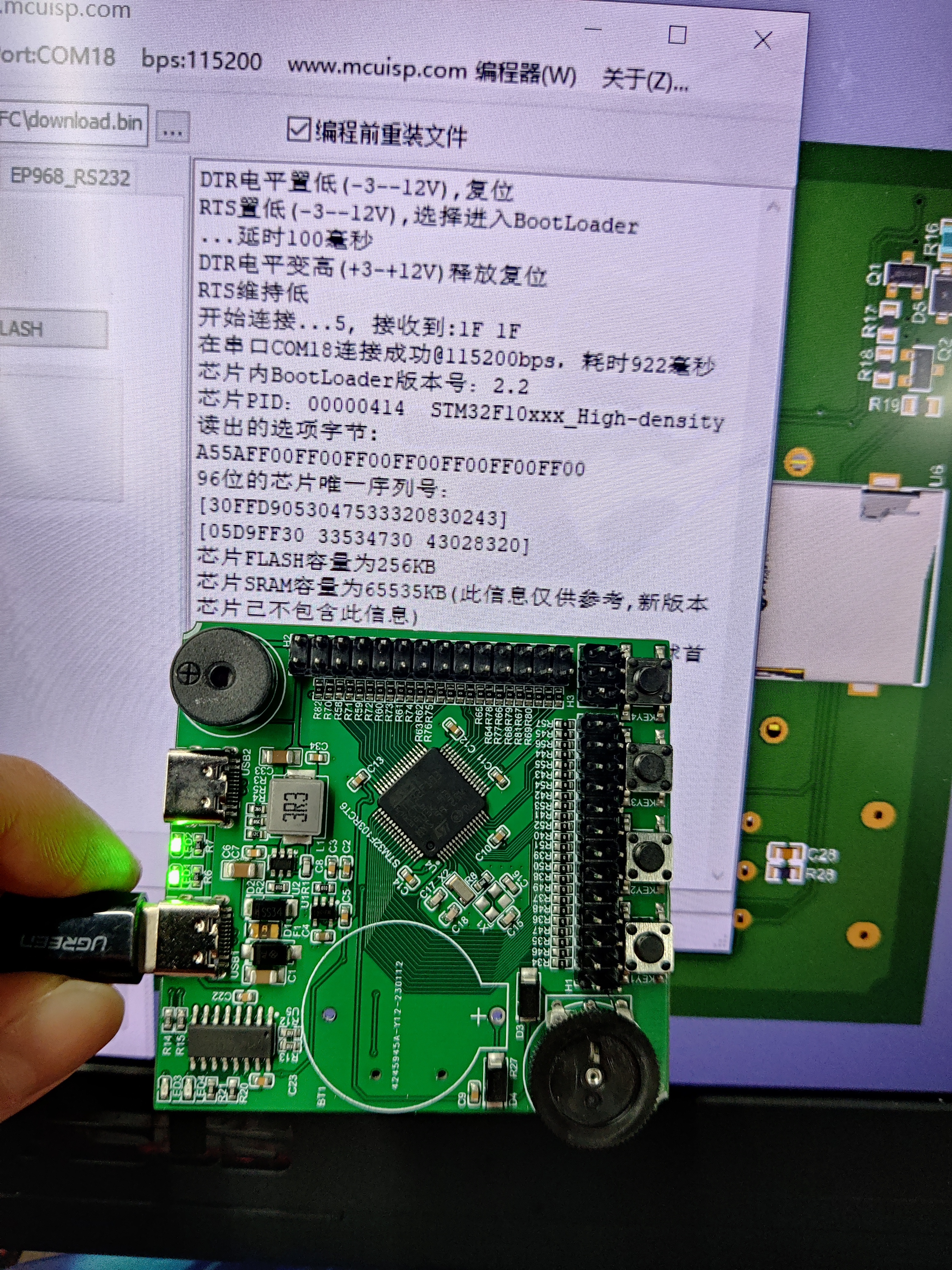

1. Type-C connection, one-button serial port download, with a visible indicator light during the download process.
2. High-efficiency power supply, converting USB 5V to 3.3V, supporting up to 2A output, input protection, and overload protection, with a power indicator light.
3. All GPIO pins are output and have built-in protection.
4. 3.3V and 5V power supplies are output. The 3.3V power supply is for output only; the 5V power supply disables output when there is input and outputs when there is no input.
5. Includes two standard buttons, KEY1 and KEY2, readable by the STM32F103RCT6.
6. Includes an indicator light connected to one PWM interface of the STM32F103RCT6 and controlled by the STM32F103RCT6.
7. Includes a passive buzzer connected to one PWM interface of the STM32F103RCT6 and controlled by the STM32F103RCT6.
8. Includes a reset button and supports manual control of the BOOT pin level to configure the download mode.
9. Includes a wake-up button to wake the STM32F103RCT6 from sleep mode.
10. Includes an encoder/gear dial potentiometer, connected to one of the STM32F103RCT6's ADC interfaces for reading.
11. Supports SD card read/write.
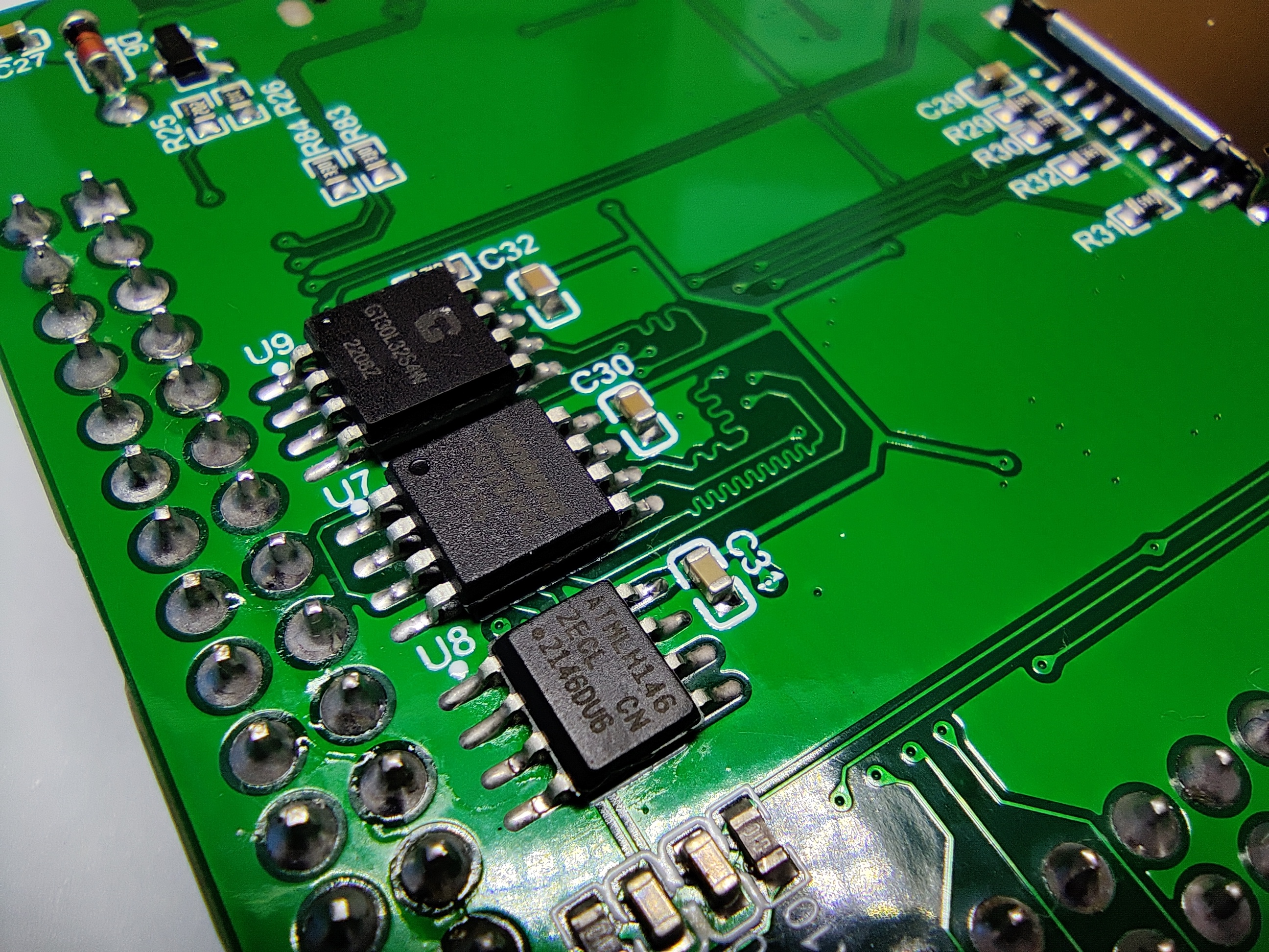
12. Expands Flash, ROM, and Chinese character libraries.
13. GPIO interface spacing conforms to a multiple of 100 mil for easy connection to external development boards.
STM32F103R.pdf
PDF_STM32F103RCT6 Core Board V221205.zip
Altium_STM32F103RCT6 core board V221205.zip
PADS_STM32F103RCT6 core board V221205.zip
97462
A smart fan project based on the Liangshan School
This powerful and intelligent fan features precise temperature sensing and multiple speed settings. It provides a more comfortable environment while being energy-efficient, allowing users to easily control fan performance.
Multiple Wind Speed Adjustment: The smart fan features five wind speed settings, allowing users to choose the appropriate speed according to their preferences.
Temperature Sensing: The fan has a built-in temperature sensor that detects the ambient temperature. When the temperature rises, the fan automatically slows down to maintain a comfortable environment.
Wind Speed Display: The fan is equipped with an LED display that shows the current wind speed in real time. This provides users with an intuitive understanding of the fan's performance.
Intelligent Control: The fan can be remotely controlled via a remote control or smartphone app, allowing users to easily adjust the wind speed and monitor the temperature.
Energy-Saving Mode: The fan also features an energy-saving mode that automatically optimizes the wind speed to reduce energy consumption, thereby lowering electricity costs.
Engineering Implementation Steps:
Design Phase: In this phase, the fan's appearance, control circuitry, temperature sensing system, and wind speed display are designed. The materials used and manufacturing processes are determined.
Manufacturing and Assembly: Manufacturing of components begins, including fan blades, motor, temperature sensor, control panel, etc. These components are then assembled into the final product.
Software Development: Embedded software is developed to control the fan's functions, including temperature sensing, wind speed adjustment, and LED display functionality.
Testing and Calibration: Conduct comprehensive testing of the fan to ensure the accuracy of the temperature sensing system, the stability of the fan speed adjustment, and the correctness of the LED display.
User Interface Development: Develop a smartphone app or remote control interface if needed, allowing users to remotely control the fan.
Production and Quality Control: Mass-produce the fan and conduct quality control to ensure each product meets standards.
Features include: speed acquisition and display; temperature and fan speed information support; charging and speed adjustment
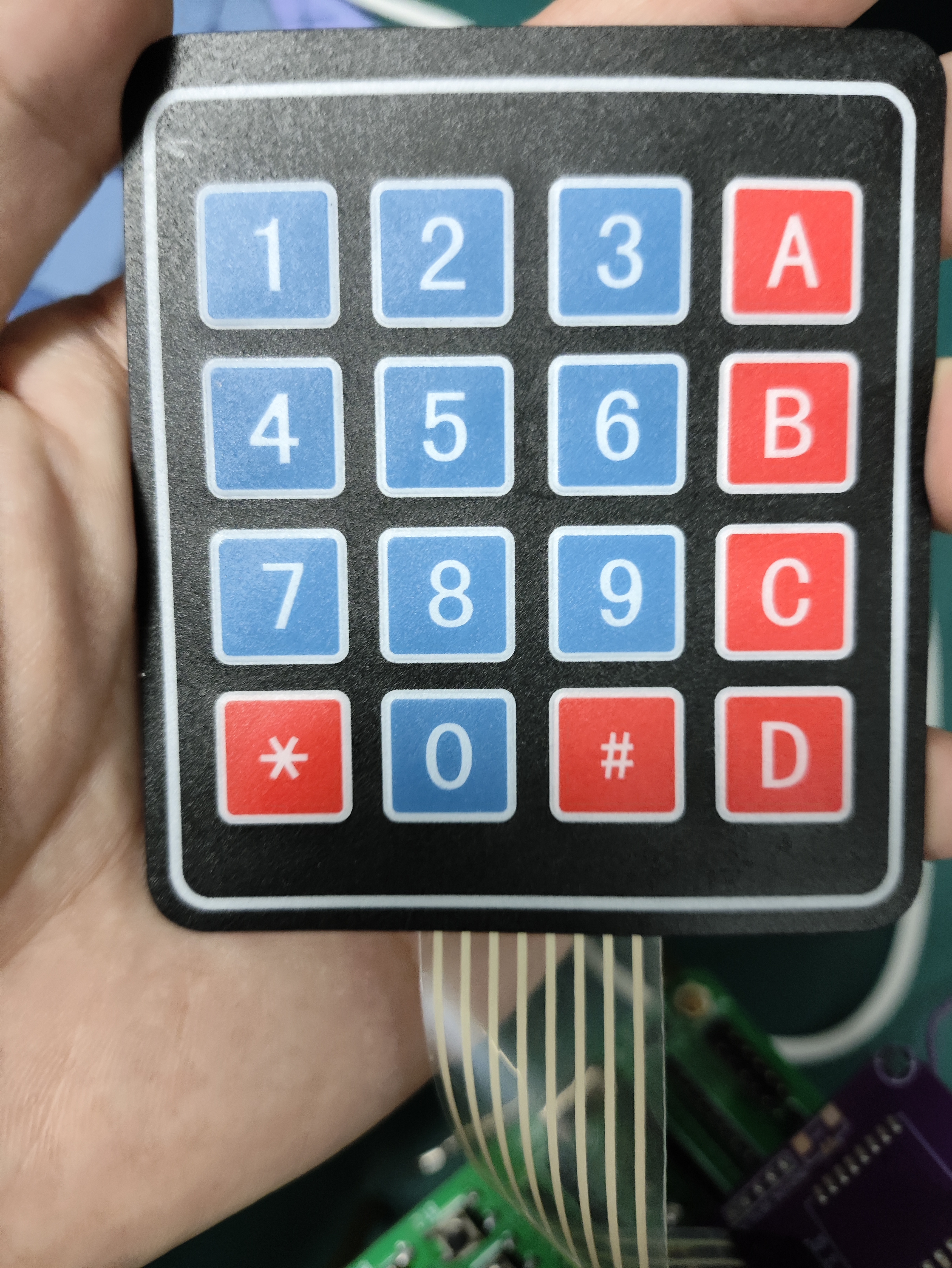
circuits ; charging circuit; boost circuit; motor drive circuit; TB661 module; matrix keyboard using row and column scanning to store key values in an array; return key 1 (upshifts speed); key 2 (downshifts speed); key 5 (switches to adaptive mode, automatically adjusts speed based on temperature); key 7 (pause).

code.zip
5778bf3e79509d0ca6267b8dd9cb6f21.mp4
PDF_Smart Fan Project Based on Liangshan School.zip
Altium_Smart Fan Project Based on Liangshan School.zip
PADS_Smart Fan Project Based on Liangshan School.zip
BOM_Smart Fan Project Based on Liangshan School.xlsx
97463
Smart Curtains
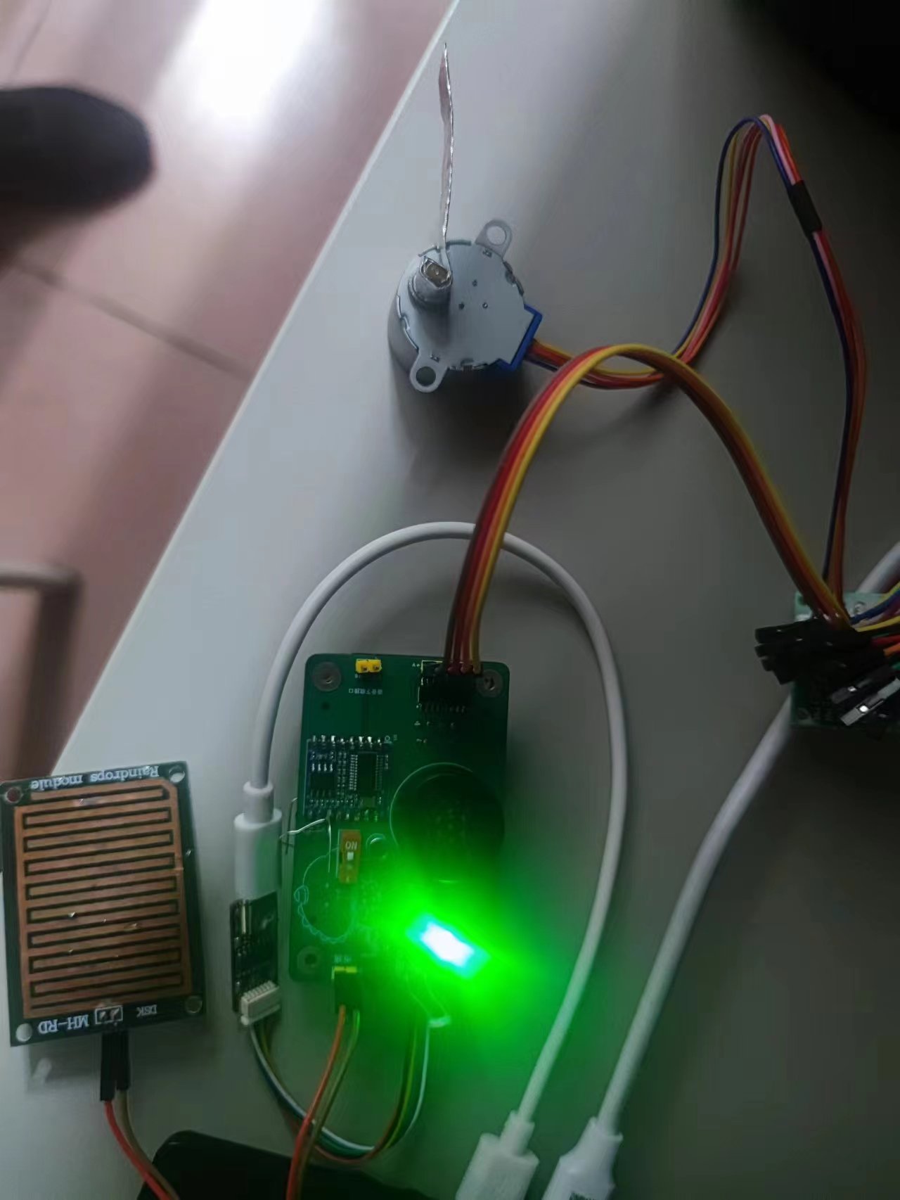
This is a small device controlled by a GD32F470zg microcontroller. Raindrop and illumination effects utilize an ADC. The stepper motor uses a timer. The voice module uses a serial port. The infrared function uses interrupts.
Voice module: HLKV-20
raindrop module: ...
Light module: GL5528 photoresistor used
. Infrared module: IRM-3638T receiver used. Remote control: NEC TV remote control from the universal remote control app on my phone.
Motor: I bought a driver board and a 5-wire 4-phase motor
![Actual object 1.jpg]
I drew the voice module incorrectly when designing the board (the pins are easy to miscount...). I could only use two wires.
If the voice module malfunctions, i.e., when the pronunciation is incomplete, you need to consider the power supply issue. I directly replaced it with a different one.
![Uploading_eb1b7581-ef57-43d2-b71c-14b5e86cbb5e]()
02+.zip
111111.mp4
PDF_Smart Curtains.zip
Altium Smart Curtains.zip
PADS_Smart Curtains.zip
BOM_Smart Curtains.xlsx
97465
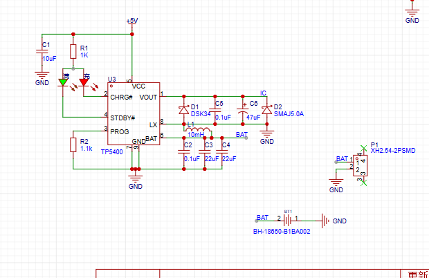
Single-cell lithium battery charge/discharge voltage regulator module
This module features charging protection to prevent overcharging and over-discharging of the battery, and automatically controls the charging current. It has a Type-C interface and retains input solder points.

Single-cell lithium battery charge/discharge voltage regulator module:
Maximum charging current: 1000mA; Charging cut-off voltage: 4.2V; Battery over-discharge protection voltage: 2.4V;
Maximum output current: 2A (recommended for use within 1A)
; Output voltage: 4~12V (can be modified to higher output).
Type-C and its adjacent VIN+ and VIN- are the power input terminals, connected to a 5V input voltage. B+ connects to the positive terminal of the lithium battery, and B- connects to the negative terminal. OUT+ and OUT- are the outputs connected to the load. A blue light illuminates, and a rapidly flashing red light indicates power is connected. After connecting the battery, only the red light illuminates; a constantly lit red light indicates charging. The blue light illuminates after a full charge. When power is connected, current is drawn from the power input terminal; otherwise, current is drawn from the battery. The output automatically shuts off when the battery voltage drops below 2.4V.
Note: When connecting the battery for the first time, there may be no voltage output; power must be applied to the power input terminal to activate the protection circuit. When using a mobile phone charger, the output must be at least 1A; otherwise, charging may not be normal.

PDF_Single-cell lithium battery charge/discharge voltage regulator module.zip
Altium single-cell lithium battery charge/discharge voltage regulator module. (zip)
PADS_Single-cell lithium battery charge/discharge voltage regulator module.zip
BOM_Single-cell lithium battery charge/discharge voltage regulator module.xlsx
97466
electronic


 京公网安备 11010802033920号

 BL-S400E-11S-XX


