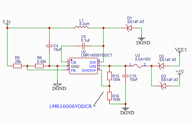
 The automotive version of LMR14006YDDCT can be used. In this case, R15 and R16 do not need to be soldered. If prolonged vehicle use is required to prevent battery drain, please calculate the voltage division values of R15 and R16 to achieve the shutdown function. If using LMR16006YDDCR, a pull-up resistor R15 must be used; otherwise, there will be no power output.
 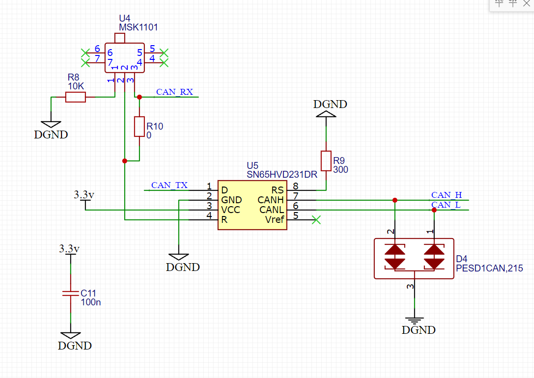 A U4 is added as a switch for the ESP32 to send CAN messages to the device. This is mainly for vehicle safety. Many new energy vehicles do not require engine starting, which can easily lead to erroneous signals triggering vehicle actions. For safety, please disable this switch. R10 is used to bypass open-source functionality; please choose according to your needs.
  Key1 is used for programming, leading to TX0 and RX0 which can be used for debugging and also support direct USB debugging. An LED is reserved for status indication; develop according to your needs.
  uses an AMS1117 power supply to ensure stability under high current.
  a minimal ESP32C3 core circuit with a USB port for easy debugging.
 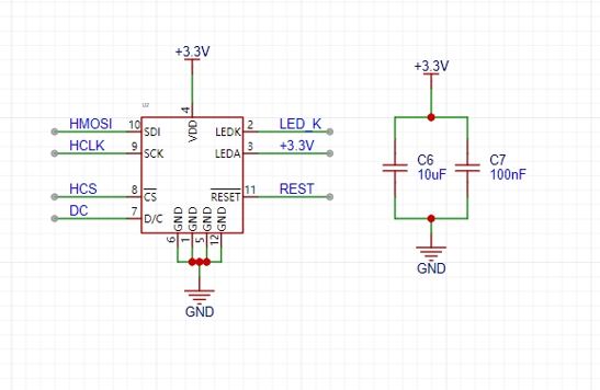 uses an SPI-driven LCD screen for display.
 Other
Other 
All reference designs on this site are sourced from major semiconductor manufacturers or collected online for learning and research. The copyright belongs to the semiconductor manufacturer or the original author. If you believe that the reference design of this site infringes upon your relevant rights and interests, please send us a rights notice. As a neutral platform service provider, we will take measures to delete the relevant content in accordance with relevant laws after receiving the relevant notice from the rights holder. Please send relevant notifications to email: bbs_service@eeworld.com.cn.
It is your responsibility to test the circuit yourself and determine its suitability for you. EEWorld will not be liable for direct, indirect, special, incidental, consequential or punitive damages arising from any cause or anything connected to any reference design used.
Supported by EEWorld Datasheet
EEWorld
subscription
account

EEWorld
service
account

Automotive
development
community

Robot
development
community

About Us Customer Service Contact Information Datasheet Sitemap LatestNews


Room 1530, 15th Floor, Building B,
No.18 Zhongguancun Street,
Haidian District,
Beijing, Postal Code: 100190
China
Telephone: 008610 8235 0740
 京公网安备 11010802033920号

 XC6203E242FH


