3D exterior shell .
was created using "Project.7z" for programming.
humidity displays .
PDF_#9th LCSC Electronics Design Contest# Desktop Temperature and Humidity Meter DIY.zip
Altium_#9th LCSC Electronics Design Contest# Desktop Temperature and Humidity Meter DIY.zip
PADS_#9th LCSC Electronics Design Contest# Desktop Temperature and Humidity Meter DIY.zip
BOM_#9th LCSC Electronics Design Contest# Desktop Temperature and Humidity Meter DIY.xlsx
The CW32 is a voltage and current meter. It features good durability and high ADC measurement accuracy, making it ideal for controlling voltage and current meters.
I. Design Background
An ADC (Analog-to-Digital Converter) is an indispensable key component in electronic systems. It converts continuous analog signals into digital signals, enabling digital processing and analysis. ADCs play a crucial role in signal conversion, measurement and data acquisition, control system input, and communication and signal processing. Their widespread application promotes the intelligent and precise control of electronic equipment across various industries, and is one of the key factors driving modern technological progress.
Digital voltmeters and ammeters combine ADC technology with circuit measurement principles, accurately converting analog voltage and current signals into digital displays for easy reading and analysis by electronic engineers. This device not only improves the accuracy and efficiency of circuit measurements but also helps engineers better understand circuit behavior, serving as a powerful assistant in electronic design and troubleshooting, and playing a vital supporting role in the work of electronic engineers. In product applications, digital voltmeters ensure the accuracy and safety of circuit design, while also providing strong support for product quality control and subsequent maintenance. Learning to design and build a digital voltmeter and ammeter
using a benchtop digital multimeter (Agilent 34401A)
is highly beneficial for improving one's professional skills. This digital voltmeter and ammeter project covers multiple aspects, including microcontroller circuit design and implementation, signal acquisition and processing circuit design, user interface development and optimization, and product appearance design. It integrates knowledge from multiple fields such as electronics, microcontroller programming, circuit design, and industrial design. Considering the learning pace and knowledge absorption capacity of beginners, we have specially launched this introductory-level digital voltmeter and ammeter project, which is very suitable for beginners in electronics and those who want to learn more about microcontroller applications. This project has the following highlights:
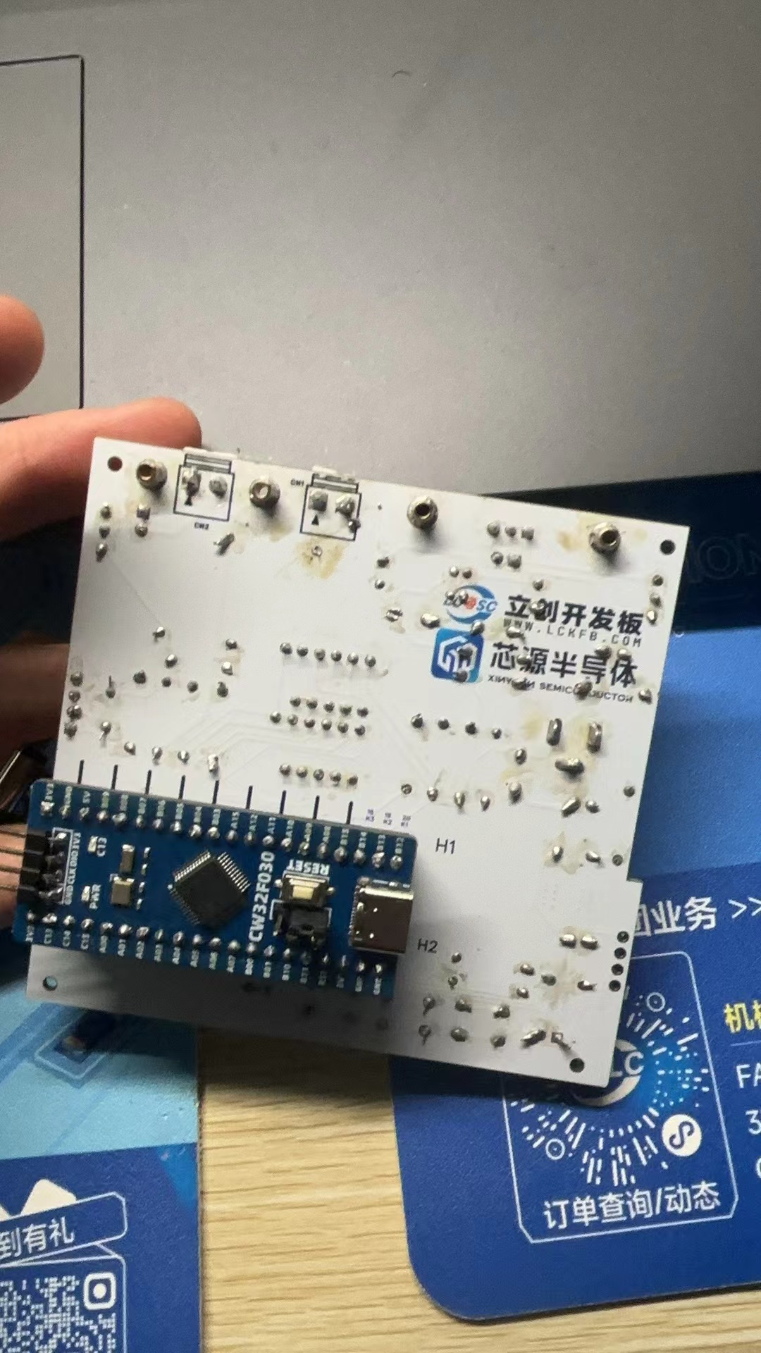
it adopts a core board plus expansion board design concept and uses plug-in components, making learning simpler and exploration more in-depth;
the core board uses the domestic Wuhan Xinyuan Semiconductor CW32 as the main controller, while also being compatible with other similar development boards; however, the CW32 has advantages.
The project is highly comprehensive and practical, and after completion, it can be used as a desktop instrument;
the project has abundant learning materials, including circuit design tutorials, PCB design, code programming learning, and training for engineers' debugging skills.
II. Hardware Design
1. Power Supply
Circuit
LDO (Low Dropout Linear Regulator) Selection
This project uses an LDO as the power supply. Considering that most voltmeter products are used in industrial scenarios with 24V or 36V power supplies, the SE8550K2 with a maximum input voltage of up to 40V was selected as the power supply. The main reason for not using a DC-DC step-down circuit to handle the large voltage drop is to avoid introducing DC-DC ripple interference during the design process; a secondary reason is to reduce project costs.
2. MCU Selection Analysis
To reduce the learning cost for everyone, this project uses the LCSC CW32F030C8Tx development board (core board) as the main controller, but this does not mean that we will talk less about this section. From the perspective of training engineers, the correct selection of the main controller is very important, as it relates to the overall advantage of the project. Regarding
the voltmeter and current meter, the author used STM32/CW32 and some other 32-bit microcontrollers for some debugging and testing. This comparison is only with the STM32F103C8T6 as a reference for device selection, primarily aimed at providing ideas and improving understanding.
Avoid blind selection.
When selecting an MCU (Microcontroller Unit) for this project, multiple aspects need to be considered to ensure the chosen MCU meets project requirements.
Clearly define your project needs: Understand the required computing power, including clock speed, processor core type, and whether a floating-point unit is needed.
Identify the required I/O ports and important peripherals, such as ADC peripherals. Since this is a development board project, primarily for debugging and learning, there are no strict limitations on the number of I/O ports: i.e., the associated costs are not considered.
Key advantages of the CW32 in this project
: Wide operating temperature range: -40~105℃;
Wide operating voltage range: 1.65V~5.5V (STM32 only supports 3.3V systems)
; Superior interference immunity: HBM ESD 8KV; All ESD reliability meets the highest international standard (STM32 ESD 2KV)
; Project focus - Better ADC: 12-bit high-speed ADC, achieving ±1.0LSB INL 11.3ENOB; Multiple Vref reference voltages... (STM32 only supports VDD=Vref);
Stable and reliable eFLASH technology.
A detailed explanation of these advantages will be provided in the chapters on ADC sampling and related extensions.
The main characteristics of the CW32 ADC:
This project requires a focus on the 4 reference voltage sources.
(Content from the "CW32x030 User Manual"
image.png )
3. Voltage Sampling Circuit:
The voltage divider resistors in this project are designed to be 220K+10K, therefore the voltage division ratio is 22:1 (ADC_IN11).
The voltage divider resistor selection
is designed to measure the maximum voltage value. For safety reasons, this project uses 30V (the actual maximum display value can be 99.9V or 100V).
The ADC reference voltage is 1.5V in this project, and this reference voltage can be configured through the program.
To reduce the power consumption of the sampling circuit, the low-side resistor (R7) is usually chosen as 10K based on experience.
Then, the high-side resistance of the voltage divider resistor can be calculated using the above parameters.
The required voltage division ratio is calculated, i.e., the ADC reference voltage. The input voltage is designed; using known parameters, 1.5V/30V = 0.05 can be calculated.
The high-side resistance is calculated as the low-side resistance/voltage division ratio; using known parameters, 10K/0.05 = 200K can be calculated.
A standard resistor is selected: a resistor slightly higher than the calculated value of 200K is chosen. We usually choose E24 series resistors; therefore, in this project, 220K, which is greater than 200K and closest to the calculated value, is selected.
If, in practical use, the voltage to be measured is lower than 2/3 of the module's design voltage, i.e., 66V, the voltage divider resistor can be replaced and the program modified to improve measurement accuracy. The following example illustrates this:
Assuming the measured voltage is no higher than 24V, and other parameters remain unchanged
, calculations show 1.5V/24V = 0.0625, 10K/0.0625 = 160K. 160K is a standard E24 resistor and can be directly selected, or a higher value 180K can be chosen with some redundancy
. In practical use… If the voltage to be measured is higher than the module's design voltage of 99V, you can choose to replace the voltage divider resistor or modify the reference voltage to achieve a larger voltage measurement range. The following example illustrates this:
Assuming the voltage to be measured is 160V, to expand the range by increasing the voltage reference
, given that the voltage divider ratio of the selected resistor is 0.0145, we can calculate 160V * 0.0145 = 2.32V using the formula. Therefore, we can choose a 2.5V voltage reference to achieve the increased range (increasing the range will reduce accuracy).
Considering the potential fluctuations in the measured power supply, a 10nF filter capacitor was connected in parallel with the low-side voltage divider resistor in the circuit design to improve measurement stability.
Range switching is
an additional voltage sampling circuit added to this project; therefore, we can discuss the significance of range switching in improving measurement accuracy. Multimeters often have multiple range settings to achieve more accurate measurements. By adjusting different ranges, the optimal measurement accuracy of the measured point within the corresponding range can be obtained.
This project requires a combination of hardware and software to implement this function. When we first use the ADC_IN11 channel mentioned earlier to measure voltages below 30V, if the measured voltage is within 0~3V, then we use the ADC_IN9 channel for measurement. At this time, due to the reduced voltage division ratio, the measurement accuracy is greatly improved.
There are many ways to implement range switching; the development board design provides more design possibilities.
4. Current Sampling Circuit
This project uses a low-side current sampling circuit for current detection. When learning the common ground between the low-side of the sampling circuit and the meter interface on the development board
, please do not solder R0!!!
The design analysis
for this project involves a sampling current of 3A, and the selected sampling resistor (R0) is 100mΩ.
The selection of the sampling resistor mainly needs to consider the following aspects:
the maximum value of the pre-designed measurement current;
the voltage difference caused by the 3A current sensing resistor in this project; and
the power dissipation of the current sensing resistor, which should generally not exceed 0.5V. A suitable package should be selected based on this parameter. Considering the power dissipation (temperature) issue under high current, a 1W metal wire-wound resistor package was chosen
. The voltage amplification factor across the current sensing resistor is also important. Since no operational amplifier is used to build the amplification circuit in this project, the factor is 1.
The current sensing resistor value can then be calculated using the above parameters
. Since no amplifier circuit is used, a larger sampling resistor is needed to obtain a higher measured voltage for measurement.
Considering that a larger resistor would result in a larger voltage drop and higher power consumption, an unlimited selection of a larger resistor is not feasible.
This project uses a 1W package resistor, corresponding to a power consumption of 1W.
Based on the above data, a 100mΩ current sensing resistor was selected. According to the formula, 3A * 100mΩ = 300mV, 900mW can be calculated.
To cope with different operating environments, especially high-current scenarios, the R0 resistor can be replaced with constantan wire or a shunt. The replacement can be selected according to the actual application scenario. For safety and educational purposes, this project will not discuss measurements exceeding 3A in detail, but the principle is the same.
5. Digital Tube Display
This project uses a digital tube as the display unit.
This project uses two 0.28-inch three-digit common-cathode LED displays as the display device. Compared to a display screen, LED displays offer better visibility in complex environments. The brightness of the LED displays can be increased by using smaller current-limiting resistors, depending on the specific needs of the application environment. Furthermore, LED displays have better mechanical properties and are not as easily damaged by external forces as display screens. They are widely used in industrial applications where stability and reliability are crucial. From a development board learning perspective, this makes it easier to learn electronic measurement principles and related development in a targeted manner.
In this project, actual testing showed that the current-limiting resistors (R1~R6) for the LED displays were configured to 300Ω. The corresponding brightness for both red and blue LED displays was good and the brightness was soft and not glaring.
Strictly speaking, the current-limiting resistors should be added to the segments; adding them to the digits would affect the display effect. Our actual design places them in the digits to save a few resistors, but the impact on the display is not significant. Therefore, we add them to the digits for convenience.
The
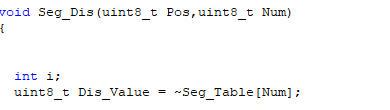
driving principle of LED displays mainly involves controlling the switching state of each segment of the LED display to display numbers, letters, or symbols. The following is a detailed explanation of the driving principle:
Basic Structure of a Digital Tube:
A digital tube typically consists of seven or eight LED segments (eight segments in this project). Each segment represents a part of the digital tube and can display numbers 0-9, letters AF, etc.
Digital tubes come in two types: common cathode and common anode. The difference lies in whether the common terminal COM (the end connecting all LEDs) is connected to the negative or positive terminal of the power supply.
Driving Methods:
Segment Selection: The desired number or character is displayed by controlling the on/off state of each segment of the digital tube. Each segment corresponds to a control signal; when the control signal is on, the segment lights up, and vice versa. (a, b, c, d, e, f, g, dp)
Bit Selection: The digital tube to be displayed is selected by controlling the bit lines of the digital tube. Bit line control sets the bit line of the digital tube to be displayed to a high level, and the bit lines of other digital tubes to a low level. By continuously switching the state of the bit lines, the display switching between multiple digital tubes can be achieved.
Driving Circuit:
The driving circuit for a digital tube can be implemented using hardware circuits, such as integrated circuits like digital signal processors (DSPs), microcontrollers (MCUs), or shift registers, to generate control signals suitable for the LEDs.
These control signals can be in the form of pulse width modulation (PWM) signals, serial data signals, etc. By controlling the frequency, width, and amplitude of these signals, the brightness of the digital tube can be controlled, thereby displaying the desired numbers or letters.
Software Control:
In addition to hardware driving circuits, the driving of digital tubes can also be implemented through software control. By programming to generate control signals suitable for the digital tubes, more flexible and complex display effects can be achieved, such as scrolling or alternating display of numbers.
Driving Common Cathode and Common Anode Digital Tubes:
For common cathode digital tubes, the common cathode pin is connected to the negative terminal of the power supply, and the control pin is connected to the output pin of the control chip. When a certain number needs to be displayed, the control chip outputs the corresponding encoded signal to the control pin, causing the corresponding LED segment to light up.
For common anode digital tubes, the working principle is similar to that of common cathode digital tubes, except that the common anode pin is connected to the positive terminal of the power supply, and the control pin is connected to the output pin of the control chip.
Encoded Display:
In order for the digital tube to display the corresponding numbers or characters, the segment data port must output the corresponding character encoding. For example, to display the number "0", the character code for a common anode seven-segment display is 11000000B (i.e., C0H), while the character code for a common cathode seven-segment display is 00111111B (i.e., 3FH). The specific code depends on the actual seven-segment display.
Dynamic and Static Display:
Seven-segment displays can use either static or dynamic display methods. In static display, each of the eight segments of a seven-segment display is connected to an 8-bit I/O port address. As long as the I/O port outputs a segment code, the corresponding character is displayed and remains unchanged. Dynamic display, on the other hand, lights up each segment of the seven-segment display one by one, achieving simultaneous visual display through rapid switching.
In summary, the driving principle of seven-segment displays is to control the switching state of each segment of the seven-segment display to display numbers, letters, or symbols, and to achieve display switching between multiple seven-segment displays through segment selection and digit selection. Simultaneously, the driving of the seven-segment display can be implemented through hardware circuits or software control, and common cathode or common anode seven-segment displays can be selected as needed.
This project actually uses dynamic scanning display to drive the seven-segment display.
Let's estimate the current required for the seven-segment display .
This project actually uses dynamic scanning to drive the digital tube, so at any given time, only a maximum of 8 segments of the digital tube (or LEDs) can be lit, or in other words, only one segment can be lit. According to the design, the required driving current is approximately 11mA, which is the high-level voltage of the IO port 3.3V ÷ 300Ω.
At this point, it is important to ensure that the selected MCU has sufficient current sinking/pull-up capability.
Analysis of the datasheet shows that the CW32 has no problem. (Some chips are not suitable.)
6. LED Indicator
This project additionally designed a power indicator and an IO working indicator.
LD_PWR is the power working indicator .
Since the chip I/O often has a greater current sinking capability than a current pulling capability, LED1 is designed to be active low (on).
To reduce the current consumption of the LED, some LED brightness is sacrificed, the number of component parameters is reduced, and the current limiting resistor for the LED is selected as 10K.
7. Button Circuit Design
There are various ways to design the button control circuit. Thanks to the fact that the CW32's I/O port can be configured with pull-up and pull-down resistors internally, the button control circuit on the outside of the chip does not need to be configured. One end of the button is connected to the MCU's I/O, and the other end is grounded. When the button is pressed, the I/O is pulled low.
8. TL431 Circuit Design for Voltage Measurement and Calibration
This project adds an extra TL431 circuit to provide a 2.5V reference voltage, which can be used to provide an external voltage reference for the chip to calibrate the AD converter. From a product design perspective, due to the inherent ADC performance advantages of the CW32, this circuit is not necessary. This circuit is designed on the development board to learn the relevant application principles.
The TL431 is a relatively "old" device, very classic, and widely used; it is still found in many electronic products.
Many beginners may be encountering this device for the first time, so we will briefly explain the principles of this product to help everyone better apply the TL431.
TI defines it as a precision programmable reference. On the first page of the references, we can focus on several key characteristics.
Precision: Precision indicates that its output voltage is very accurate. I used a TL431 with ±0.5% accuracy, and the measured voltage on the board at room temperature was 2.495V. Compared to common Zener diodes, the precision is vastly different. In application circuit diagrams, the TL431 is internally represented by a Zener diode symbol.
Adjustable output voltage: The adjustable output voltage is between Vref and 36V. In our project, we use the output Vref voltage. Vref voltage is approximately 2.5V. Therefore, we use 2.5V in the description, which is approximately equal to 2.5V in reality.
Sinking current capability: This refers to how much current the output voltage pin can provide, which is greatly related to the resistance value (R13) in the application circuit. It should not be less than 1mA. If there is no need for sinking current, do not design the current to be too high, causing unnecessary power consumption.
Reflections after completing the project:

Completing a complete project for the first time was quite challenging, with different requirements from the schematic to the PCB. I learned a lot. However, there are still many shortcomings. First, the placement of the schematic was not standardized, and several important lines were only discovered to be missing after the board was fabricated. The final board had many problems, but the first few experiments were still completed.

Learn how to use the CW32 microcontroller and design voltage and current meters through the training camp.
This project was created based on the official CW32 digital voltmeter and ammeter training camp tutorial document from LCSC | LCSC Development Board Technical Documentation Center (lckfb.com).
Hardware Notes:
1. For the upper measurement section, it is recommended to use thicker terminals. I found that the pin header's rated current is exactly 3A, and to exceed the required measurement range, it is recommended to replace it with one capable of handling a larger current.
2. Pay attention to the power rating of the resistors, especially the 100MR R0. To achieve the 3A measurement range, a package of 1W or higher is needed.
3. It is recommended to use a 3296W resistor with a handle for easy value adjustment.
4. After soldering, it is recommended to use a multimeter to check for short circuits between the power supply and ground, as there will be a significant voltage difference. For safety, ensure there are no short circuits.
5. Pay attention to the polarity of the aluminum electrolytic capacitors, clamping diodes, and LEDs.
Software: Refer to LCSC's official example code.
Pay attention to the final voltage and current calibration; otherwise, there will be some errors.
For voltage calibration, press K1, connect JP1, set the multimeter to voltage mode (greater than 15V), insert T_V and T_GND. When the voltmeter displays 5V, press K2 to complete the 5V calibration; press K2 twice to enter the 15V calibration, and so on.
For current calibration, R0 needs to be soldered, JP2 does not need to be shorted, set the multimeter to current mode (greater than 3A), connect the power supply positive to CN2, and the negative to the left side of CN1. Adjust the power supply to perform 0.5A and 1.5A calibrations.
(The above points are basically problems I encountered during the production process. Since I don't have an adjustable power supply on hand, I couldn't perform current calibration, so I only performed voltage calibration, which is accurate as you can see from the cover. Also, the 3D file was incorrect; the screw holes around the edges prevented the board from fitting, so the 3D shell production failed.)
The voltage and current meter based on the CW32 development board uses two 3-digit LED displays.
I. Project Introduction
This project is a LCSC training camp project, using a CW32 development board + expansion board to build a voltage and current meter. The components are designed with basic sampling plug-in type for easy soldering.
The main control core board uses the domestic Wuhan Xinyuan Semiconductor CW32 as the main controller, while also being compatible with other similar development boards; however, the CW32 has advantages.
The training camp provides rich design documents, explaining everything from component selection to circuit design and software design, for in-depth learning.
Training camp document link: CW32 Digital Voltage and Current Meter Training Camp Project Tutorial Document | LCSC Development Board Technical Document Center (lckfb.com)
Accompanying video link: LCSC Development Board Personal Space - LCSC Development Board Personal Homepage - Bilibili Video (bilibili.com)
II. Hardware Design
1. Power Supply Circuit

LDO (Low Dropout Linear Regulator) Selection This project uses an LDO as the power supply. Considering that most actual voltage meter products are used in industrial scenarios with 24V or 36V power supplies, this project selected the SE8550K2 with a maximum input voltage of up to 40V as the power supply. The main reason for not using a DC-DC step-down circuit to handle large voltage differences in this project is to avoid introducing DC-DC ripple interference during the design process. A secondary reason is to reduce project costs.
2. Advantages of the CW32 development board
: Wide operating temperature range: -40~105℃;
Wide operating voltage: 1.65V~5.5V (STM32 only supports 3.3V systems)
; Strong anti-interference: HBM ESD 8KV; All ESD reliability reaches the highest international standard level (STM32 ESD 2KV)
; Project focus - Better ADC: 12-bit high-speed ADC, achieving ±1.0LSB INL 11.3ENOB; Multiple Vref reference voltages... (STM32 only supports VDD=Vref);
Stable and reliable eFLASH technology.
CW32's ADC main characteristics.

3. Voltage sampling circuit: The voltage
divider resistor in this project is designed to be 220K+10K, so the voltage division ratio is 22:1 (ADC_IN11).
The voltage divider resistor
is selected to measure the maximum voltage. For safety reasons, this project uses 30V (the actual maximum can be displayed as 99.9V or 100V).
The ADC reference voltage is 1.5V in this project, and this reference voltage can be configured through the program.
To reduce the power consumption of the sampling circuit, the low-side resistor (R7) is usually chosen as 10K based on experience.
Then, the high-side resistance of the voltage divider resistor can be calculated using the above parameters.
The required voltage division ratio is calculated, i.e., the ADC reference voltage. The design input voltage can be calculated using known parameters: 1.5V/30V = 0.05.
The high-side resistance is calculated as: low-side resistance/voltage division ratio. Using known parameters, 10K/0.05 = 200K.
A standard resistor is selected: a resistor slightly higher than the calculated value is chosen. The calculated value is 200K. We usually choose E24 series resistors; therefore, in this project, 220K, which is greater than 200K and closest to the calculated value, is selected.
4. Current Sampling Circuit:
This project uses a low-side current sampling circuit for current detection. The low-side of the sampling circuit shares a common ground with the development board's meter interface.
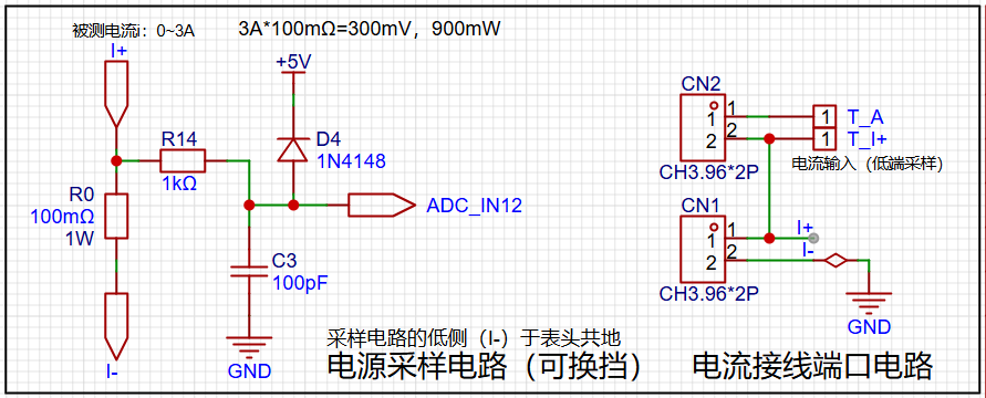
The design analysis shows
that the sampling current in this project is 3A, and the selected sampling resistor (R0) is 100mΩ. According to the formula, 3A * 100mΩ = 300mV, 900mW. The
program
defines 5 working modes. The SW1 key is used to switch the display mode. The SW2 key sets the parameter value for the corresponding mode and saves it to FLASH. The SW3 key returns to mode 0.
Mode 0: Displays normal voltage and current values (the upper row of digital tubes displays the voltage value *.V or .*V automatically, the lower row displays the current value _.**A).
Mode 1: 5V voltage calibration setting. The upper row of digital tubes displays 5.05. The lower row displays the current voltage value _.V or ._V. In this mode, the multimeter should be set to 5.00V to measure the measured bit. After pressing the SW2 key, the current value is calibrated to 5V.
Mode 2: 15V voltage calibration setting. The upper row of digital tubes displays 5.15. The next row displays the current voltage value as _.V or ._V. In this mode, the multimeter should be set to 15.0V when measuring the measured part. After pressing the SW2 key, the current value is calibrated to 15V.
Mode 3: Current 0.5A calibration setting. The upper row of the digital tube displays A.0.5. The next row displays the current current value as _.**A. After pressing the SW2 key, the current value is calibrated to 0.5A.
Mode 4: Current 1.5A calibration setting. The upper row of the digital tube displays A.1.5. The next row displays the current current value as *.**A. After pressing the SW2 key, the current value is calibrated to 1.5A.
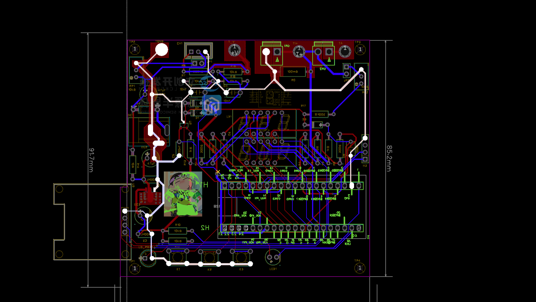
 PCB
PCB 
 layout, physical renderings, and
 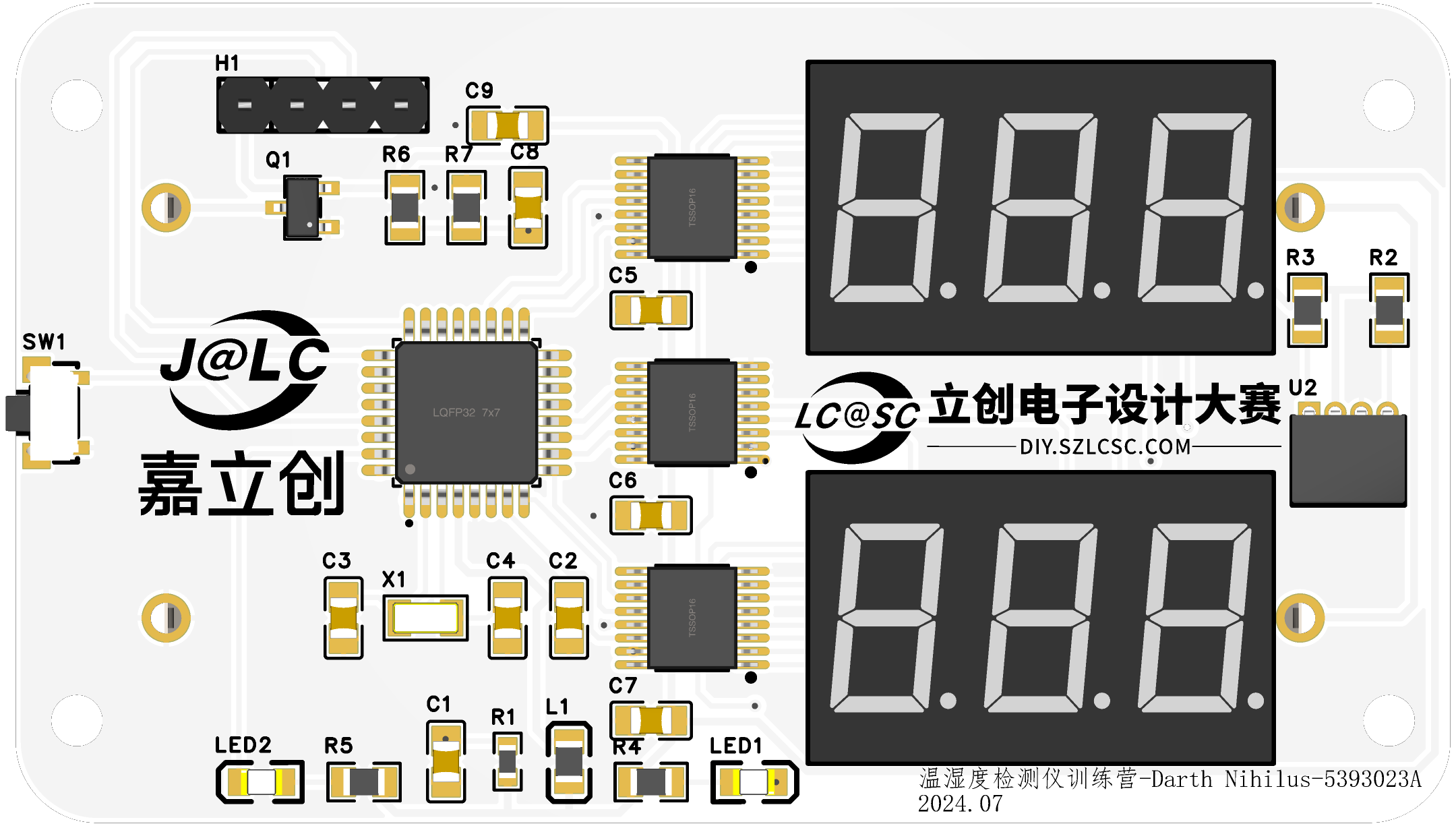 a
a 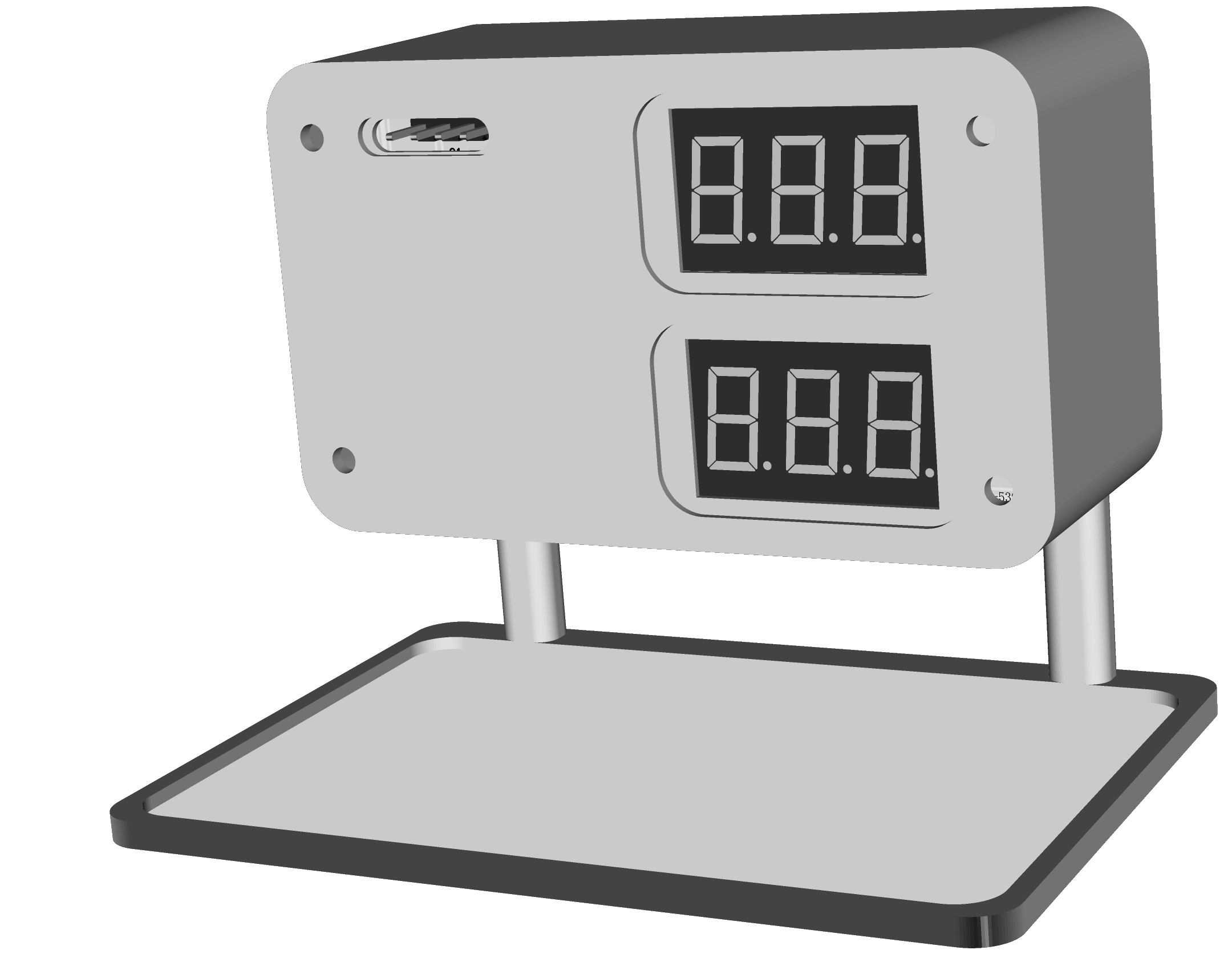 The software design
 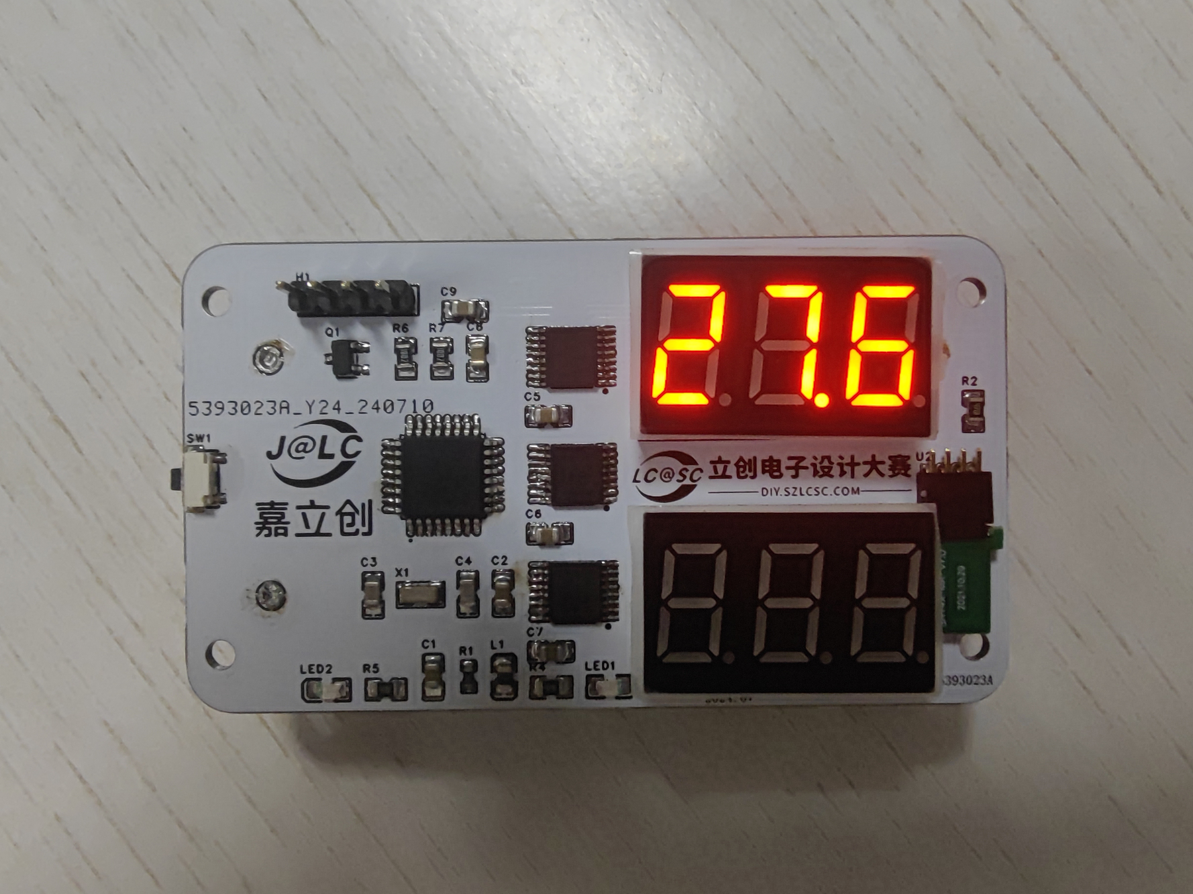 humidity displays .
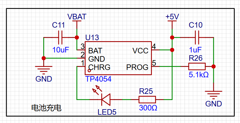 A small current, small battery was used; the TP4054 was inexpensive and practical .
  The more commonly used 78M05 LDO was chosen, with a maximum input of 35V.
 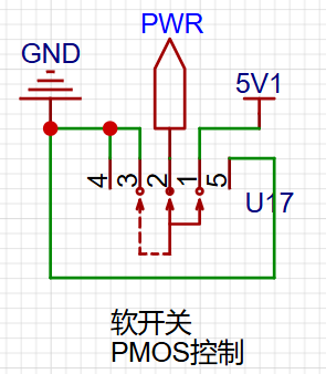 When an external power source is available, the battery does not provide power.
 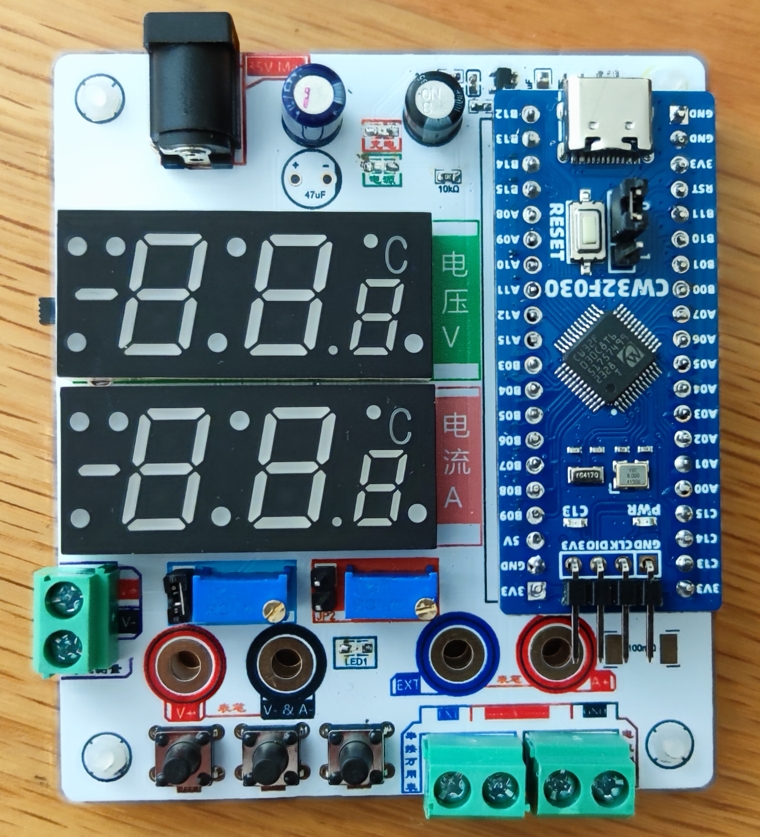 : Thanks to JLCPCB for providing color silkscreen printing; I tried it out, and the output was good, although the printing time was slightly longer than with regular silkscreen printing.
 The common cathode encoding is still used, but it is inverted during use. Simultaneously, the COM terminal level also needs to be reversed
  to successfully measure the external power supply voltage.


 京公网安备 11010802033920号

 HF116F-1/003AP-2HTFWCXXX


