I. Project Description
Common wired communication protocols used in smart homes include RS485, RS232, CAN, Ethernet, PLC, and KNX. Ethernet is a commonly used wired communication protocol suitable for data transmission and internet connectivity in smart homes. Through Ethernet, smart home devices can connect to routers or gateways to achieve remote control and internet access.
This project mainly demonstrates the application scenarios of Ethernet in smart home systems for PoE power supply, device networking, and control.
II. Open Source License
This project uses the CC-BY-NC-SA 3.0 license. Please adhere to the license specifications!
License Name:
CC-BY-NC-SA 3.0
Creative Commons License - Attribution-NonCommercial-ShareAlike
Introduction:
The above licenses are all Creative Commons licenses. The letters in each part represent:
CC: Abbreviation for Creative Commons license;
BY: Attribution. You must give appropriate attribution, provide a link to this license, and indicate whether modifications were made (to the original work).
SA: Share Alike. If you remix, transform, or create based on this work, you must share and distribute your contributions under the same license as the original.
NC: Non-Commercial. You may not use this work for commercial purposes.
ND: No Derivatives. If you remix, transform, or create based on this work, you may not share and distribute the modified work.
III. Project Progress and Module Functions
| No.
| Name |
Progress |
Function |
Remarks | |---|---|---|---|---| |
1 |
W5500+TPS2378 | POE Module
| Completed all verifications
| Ethernet, POE power supply
obsolete*¹ |
| 2
| DC-DC Single-Channel Power Supply Module |
Completed all verifications |
7V to 60V input, 5V 5A output |
| 3
| Gigabit Ethernet Cable Connection Module
| Completed all verifications
| Cable extension, ordinary network port to POE port |
| 4 | TPS23861
PSE Control Module
| Completed all verifications
| POE power supply control |
| 5
| DC-DC Dual-Channel Power Supply Module
| Completed all verifications |
60V input, 5V+12V output |
| 6
| ESP32 Control Module |
Completed all verifications
| Ethernet, POE power supply, device control |
Replacement of Module ① |
| 7
| MCP23017 IO Control Module |
Completed all verifications |
8-channel input +
8 -channel output control
| Note: *¹ W5500 replaced with LAN8720, subsequent modules will be uniformly upgraded to adopt UM90 DIN rail housing design.
IV. Physical Demonstration
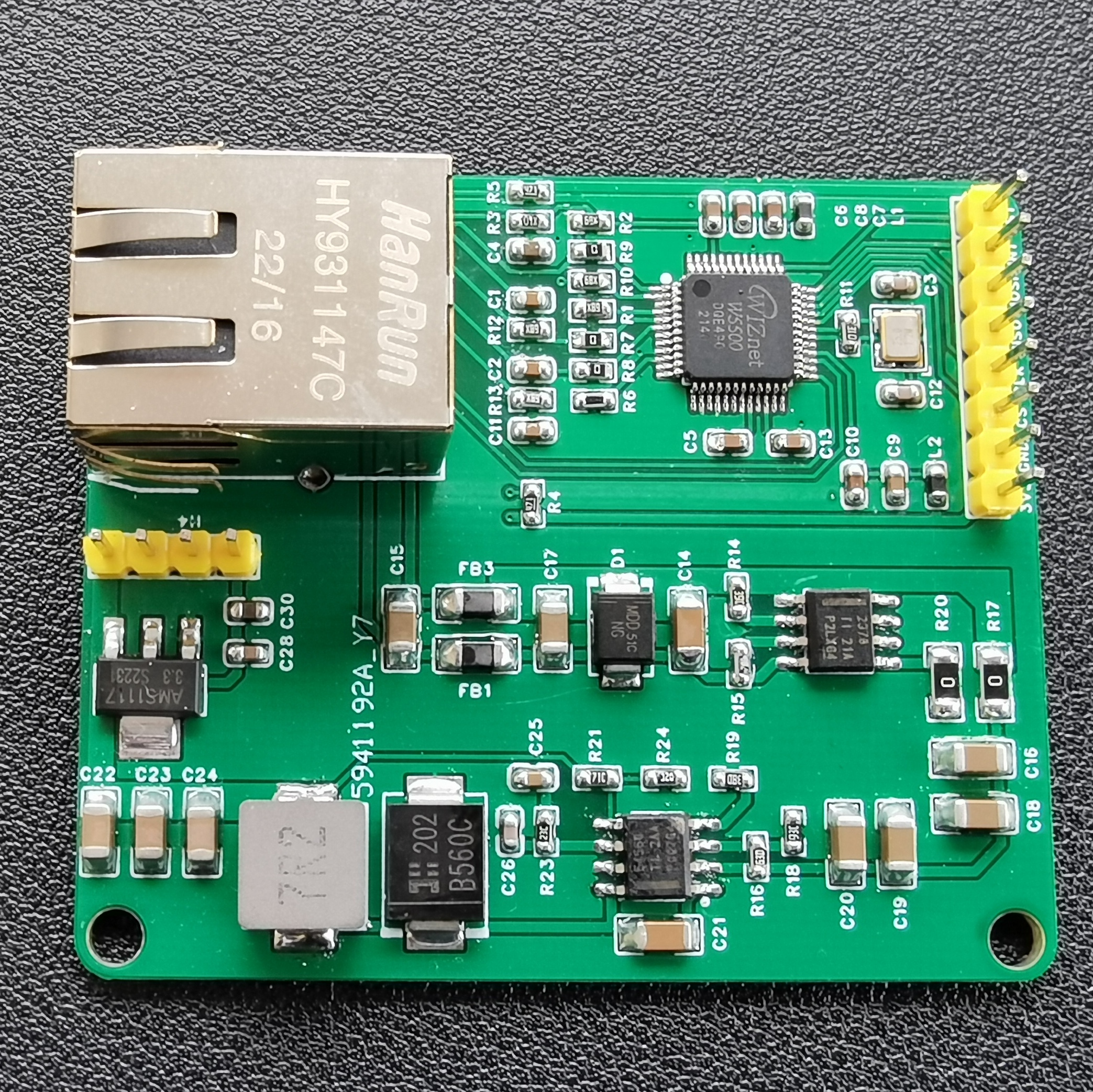
Module ①: W5500+TPS2378 POE Module
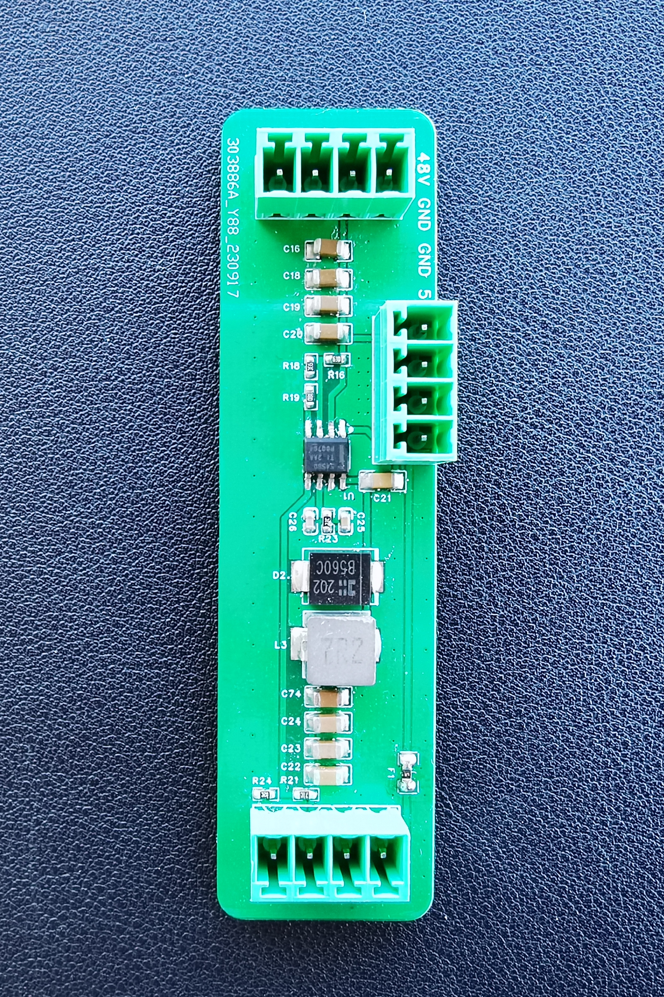
②: DC-DC Single-Channel Power Supply
Module ③: Gigabit Ethernet Cable Connection

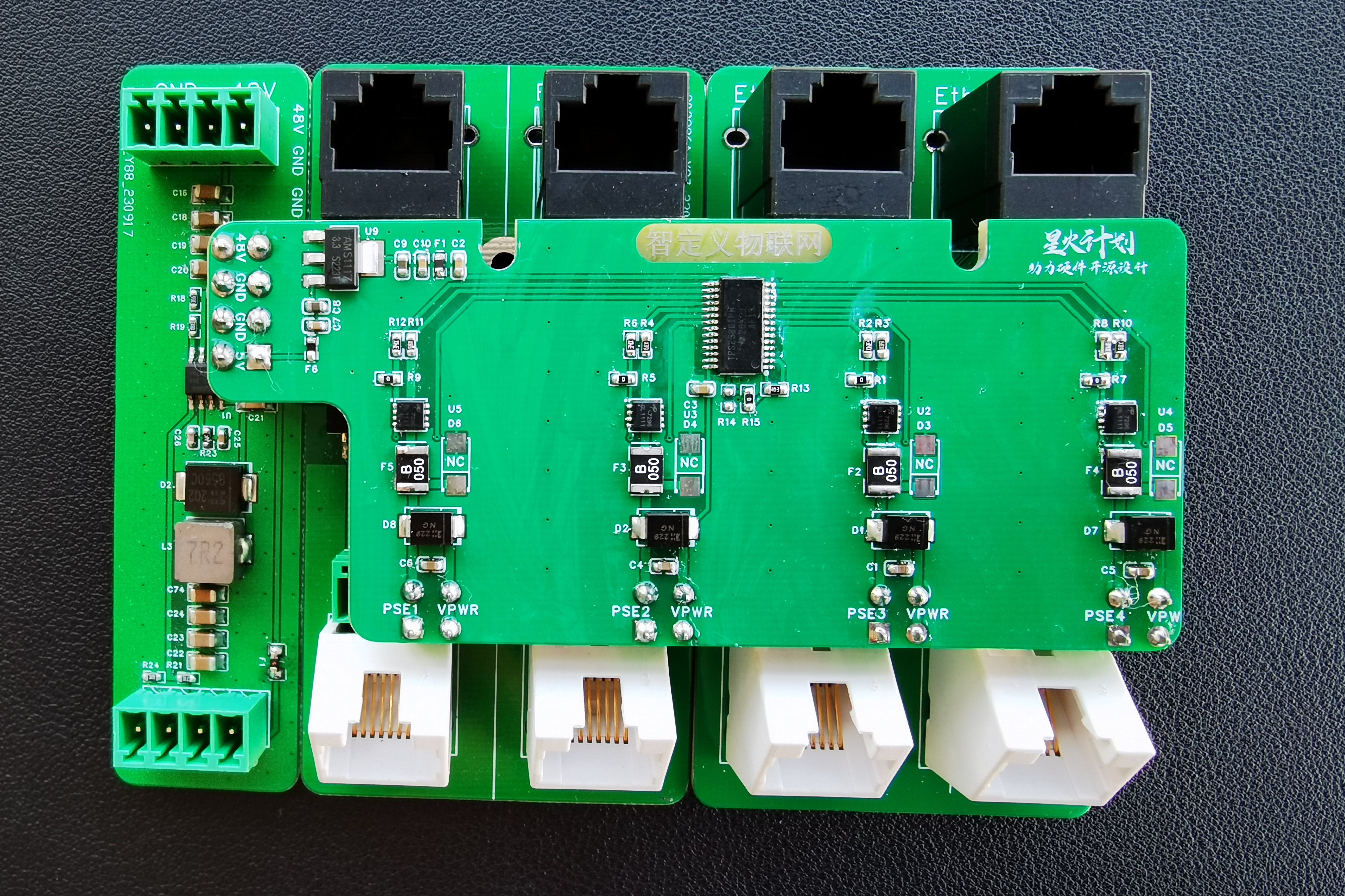
Module ④: TPS23861 PSE Control

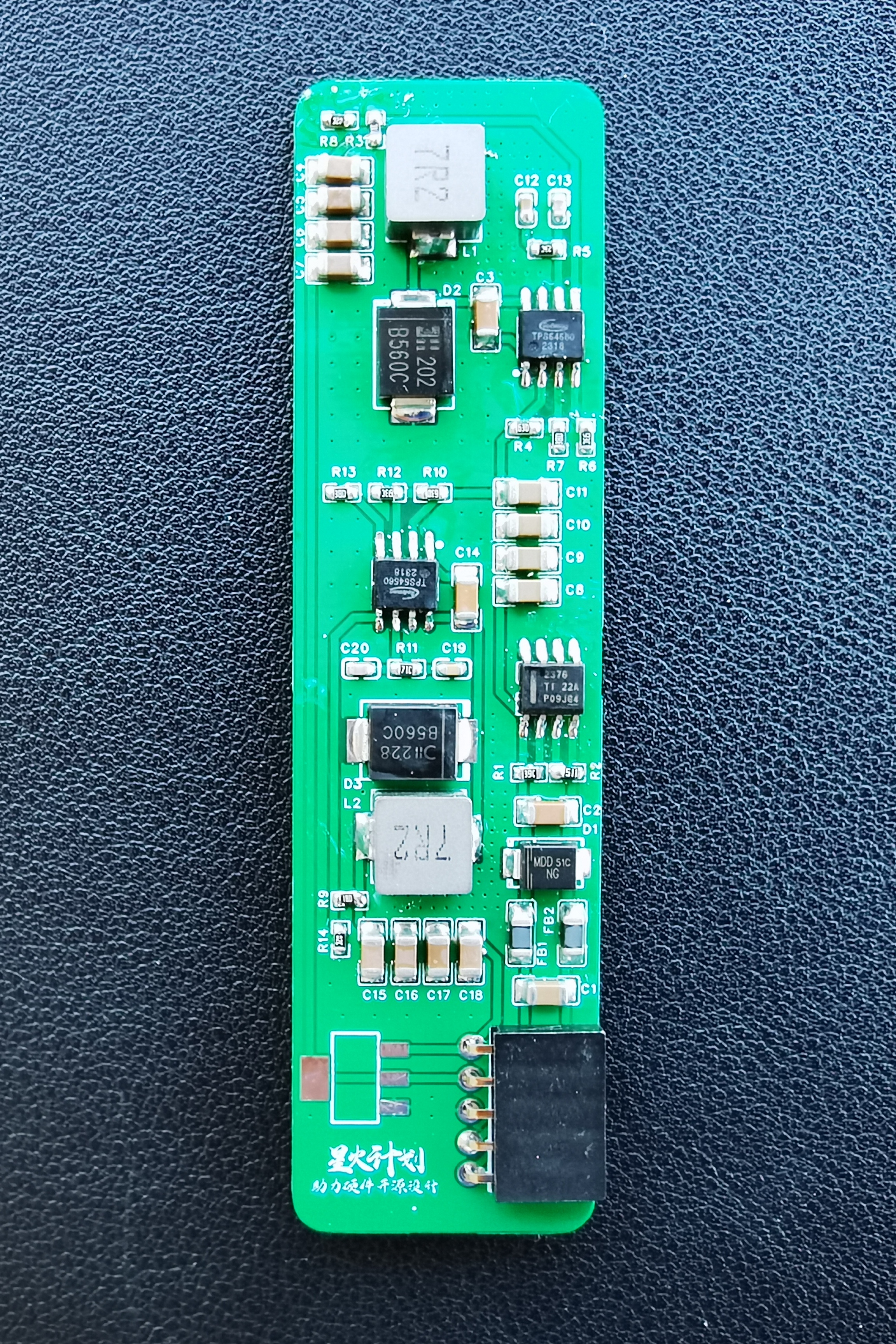
Module ⑤: DC-DC Dual-Channel Power Supply
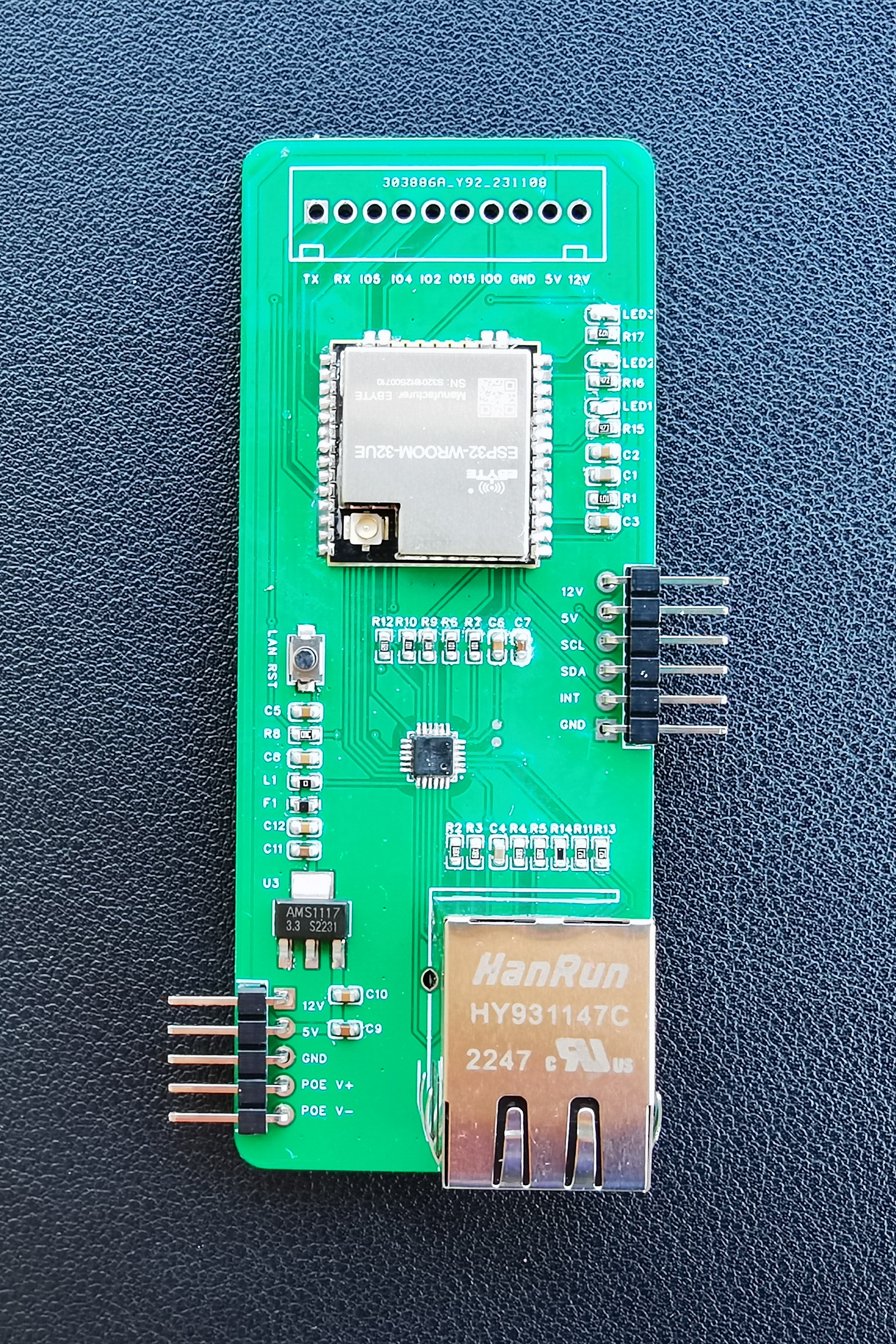
Module ⑥: ESP32 Control Module
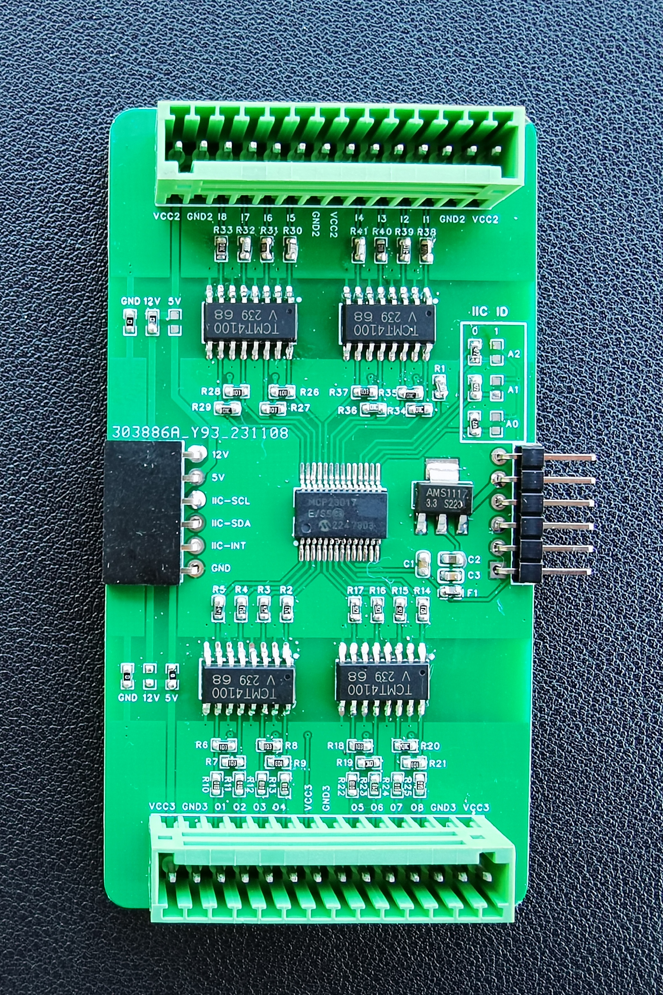
⑦: MCP23017 IO Control Module
Combination 1
Combination 2
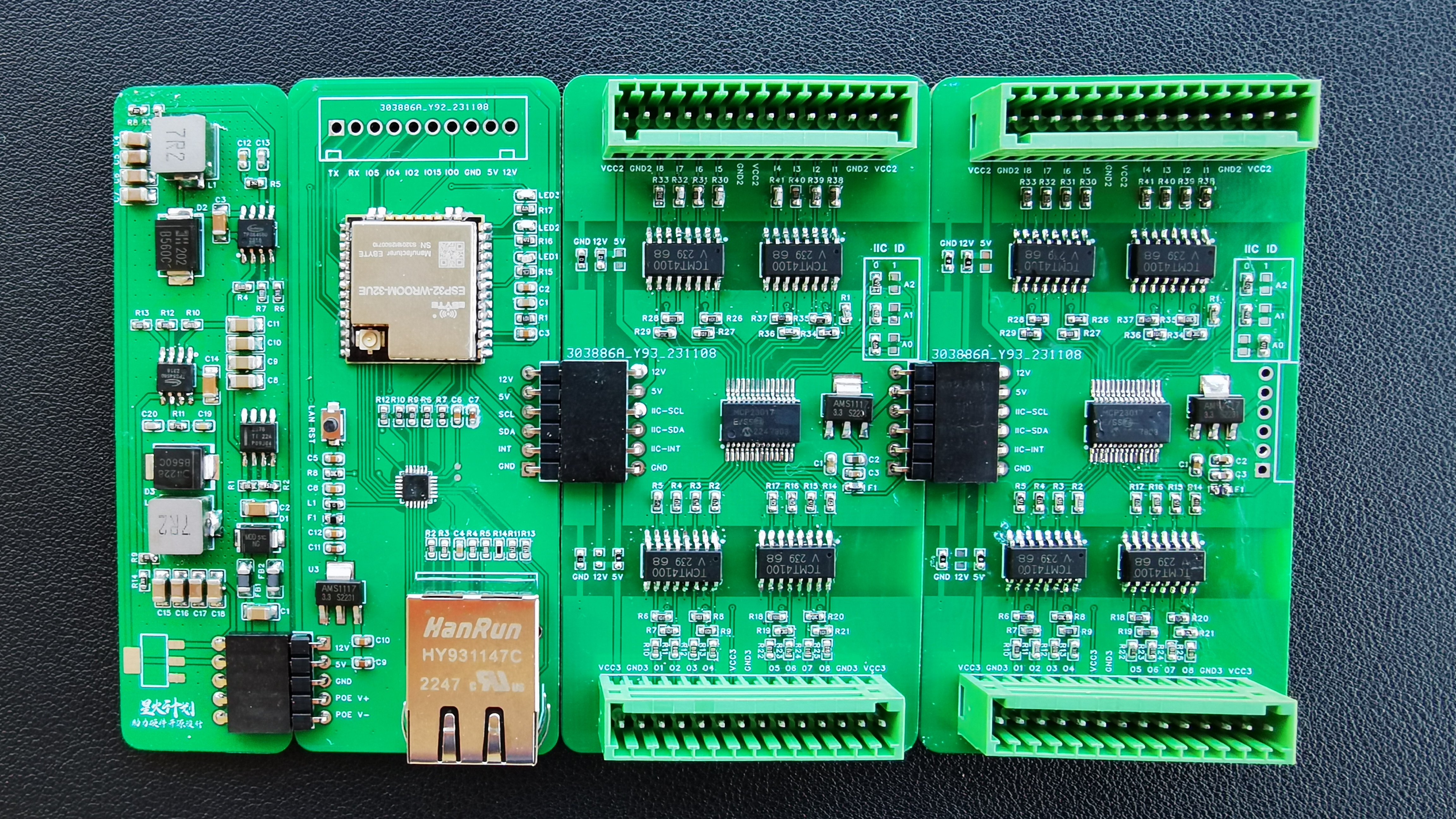
Overall View

V. Physical Function Demonstration
W5500-POE Module LED Power Supply Test: https://www.bilibili.com/video/BV1PL411r7Pa/
W5500-POE Module Fan Power Supply Test: https://www.bilibili.com/video/BV1rb411Z76Y/
W5500-POE Module IP Address Acquisition: https://www.bilibili.com/video/BV1uT411D7ks/
Gigabit Ethernet Cable Connection Module Network Speed Test: https://www.bilibili.com/video/BV1MC4y1o7pr/
ESP32+MCP23017 IO Expansion Test: https://www.bilibili.com/video/BV1Rb4y1g71c/
System Introduction and Test: https://www.bilibili.com/video/BV1nc411r7LJ/
VI. Sub-module Working Principle
(I) PSE Power Supply Module
① POE Power Supply Detection Circuit The
TPS23861 determines whether to supply power to the device by detecting the current at the power supply port. The GATE, DRAIN, and SEN pins control the circuit's on/off state. The SEN pin detects the current, GATE controls the on/off characteristics of the external high-power MOSFET, and DRAIN provides the basic drain voltage. When no PD device is connected, GATE controls the power supply to the external device by switching the MOSFET on and off. When the load does not meet the requirements, the basic current detected by SEN is very small, and GATE will not be in a normally open state. When a load is present, the current flowing back to SEN will be large, and the chip will detect a current that meets the requirements and keep the GATE gate in a normally open state. This realizes the detection circuit for POE device power supply.
②PoE Power Negotiation Process:
After the PSE device is powered on and the PD device connects to the PSE device via the network, the PSE and PD begin power negotiation:
PD Detection: The PSE periodically outputs a small, current-limited voltage at the port to detect the presence of a PD device. If a specific resistance value is detected, it indicates that the cable termination is connected to a powered device supporting the IEEE 802.3af or IEEE 802.3at standard (a specific resistor with a resistance value between 19kΩ and 26.5kΩ, a typical small voltage of 2.7V to 10.1V, and a detection cycle of 2 seconds). Power Capability Negotiation (PD Device Classification Process): The PSE classifies the PD and negotiates the power supply. Power capability negotiation can be achieved not only by resolving the resistance sent by the PSE and PD, but also through the Link Layer Discovery Protocol (LLDP) to discover and announce power capabilities. Start-up Power Supply: During the startup period (generally less than 15μs), the PSE device begins to supply power to the PD device from a low voltage until a 48V DC voltage is provided. Normal Power Supply: After the voltage reaches 48V, the PSE provides a stable and reliable 48V DC power to the PD device, and the PD device's power consumption does not exceed the PSE's maximum output power. Power outage: During power supply, the PSE continuously monitors the PD current input. When the PD current consumption drops below the minimum value, or the current surges, such as when the device is unplugged or when the PD device experiences power consumption overload, short circuit, or exceeds the PSE's power supply load, the PSE will disconnect the power and repeat the detection process.
(II) The PD power receiving module
TPS2378 can realize all the functions required for IEEE802.3at Class 2 powered devices (PDs). The controller has an internal switching resistance as low as 0.5Ω and uses a thermally enhanced PowerPAD package, which can operate at currents up to 0.85A for a long time. The TPS2378 has an auxiliary power detection (APD) input, which can preferentially connect to an external power adapter. It also features a 100V turn-on transistor, 140mA surge current limit, Class 2 indication, automatic retry fault protection, and open-drain power supply normal status output.
① Pin description (the red-marked devices correspond to the devices in the schematic diagram below)
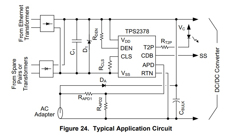
Pin2: DEN
The DEN (Detection and Enable) pin implements two independent functions. A resistor (RDEN) connected between the DEN pin and VDD generates a detection signature when the voltage difference between VDD and VSS is between approximately 1.4V and 10.9V. Outside this range, the controller disconnects the resistor to conserve power. The IEEE 802.3at standard specifies the detection signature resistor RDEN to be between 23.75 kΩ and 26.25 kΩ, or 25 kΩ ± 5%. TI recommends using a resistor of 24.9 kΩ ± 1% for RDEN. If the resistor connected between VDD and DEN is divided into two approximately equal parts, the application circuitry can disable the PD (Powered Device) by grounding the junction between the two resistors. This operation also destroys the detection signature, thus signaling to the Powered Device (PSE) that the PD no longer requires power.
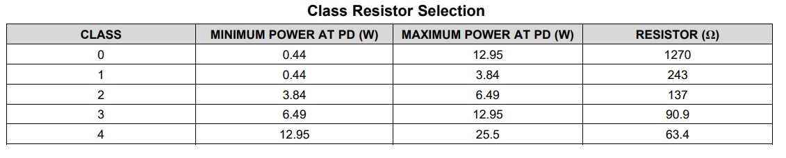
Pin 3: CLS
An external resistor (RCLS) connected between the CLS pin and VSS provides a classification signature to the PSE. When the voltage difference between VDD and VSS is between approximately 10.9V and 22V, the controller applies approximately 2.5V to the external resistor. The current drawn by this resistor, plus the controller's internal current and any leakage current through the internal channel MOSFET, together form the classification current. The table below lists the external resistor values required for each PD power range as defined by IEEE 802.3at. The maximum average power received by the PD, plus the power supplied to downstream loads, should not exceed the maximum power indicated in the table. Holding APD high disables classification signature. High-power PSEs may perform two classification cycles when Class 4 occurs in the first cycle.
Pin 5: RTN
The RTN pin of the internal channel MOSFET provides a path for the negative power supply loop. Once VDD exceeds the undervoltage lockout threshold, the internal channel MOSFET pulls RTN to VSS. Inrush limiting prevents the RTN current from exceeding approximately 140 mA until the bulk capacitor (CBULK) is fully charged. Inrush ends when the RTN current drops below approximately 125 mA. Subsequently, the RTN current is limited to approximately 1 A. CDB is pulled low to signal to the downstream load that the bulk capacitor has been fully charged. If RTN exceeds approximately 12 V for more than 800 μs, the TPS2378 will return to the inrush limiting state.
Pin 6: CDB
CDB is a low-level output pulled to RTN when the device is in inrush current limiting mode. At other times, it remains high impedance. This pin is an open-drain output and may require a pull-up resistor or other interface to the downstream load. It can be left unconnected if CDB is not used. The CDB pin can disable the startup of a downstream converter by keeping the soft-start pin low. When CDB is connected to the SS pin of a downstream DC-DC controller, it does not affect the charging time of the soft-start capacitor when it is disconnected because CDB is an open-drain output. Another common use of the CDB pin is to enable a converter with an active high-level enable input. In this case, depending on the requirements of the controller enable pin, CDB may require a pull-up resistor connected to VDD or the bias supply.
Pin 7: T2P
The TPS2378 pulls T2P to RTN when it observes a Type-2 hardware classification or an APD pin pull-high. If the chip enters a thermal shutdown state, the channel MOSFET enters inrush current limiting mode, or no Type-2 PSE is detected and the voltage on the APD is below its threshold, the T2P output will return to a high impedance state. When the voltage difference between VDD and VSS exceeds the upper classification threshold, the circuitry used to observe the Type-2 hardware classification will lock its result. When the voltage difference between VDD and VSS drops below the classification threshold, the circuitry will reset. If the T2P pin is not used, it can be left unconnected. The T2P pin is an active low-level, open-drain output indicating that a high power source is available. An optocoupler can be used to interface the T2P pin with the secondary-side circuitry of the converter. High-gain optocouplers and high-impedance (e.g., CMOS) receivers are recommended.
Pin 8: APD
. APD (Auxiliary Power Detect) is a pin used to detect auxiliary power. In some applications, the device may draw power from an Ethernet cable or auxiliary power supply. When the voltage on the APD pin exceeds approximately 1.5V relative to the RTN pin, the internal path MOSFET will turn off, the CLS output will be disabled, and the T2P output will be enabled, causing the adapter to prioritize auxiliary power over PoE (Power over Ethernet). The resistor divider (RAPD1, RAPD2) provides system-level ESD protection for the APD pin, discharges leakage current from the blocking diode (DA), and provides input voltage monitoring to ensure that the voltage does not switch to the auxiliary voltage source under excessively low voltage conditions. If the APD pin is not in use, it can be left unconnected.
(III) The DC-DC module
TPS54560 is a 4.5V to 60V input, 5A step-down DC/DC converter with Eco-Mode™. The following diagram shows a typical application schematic for a 7~60V input, 5V 5A output.
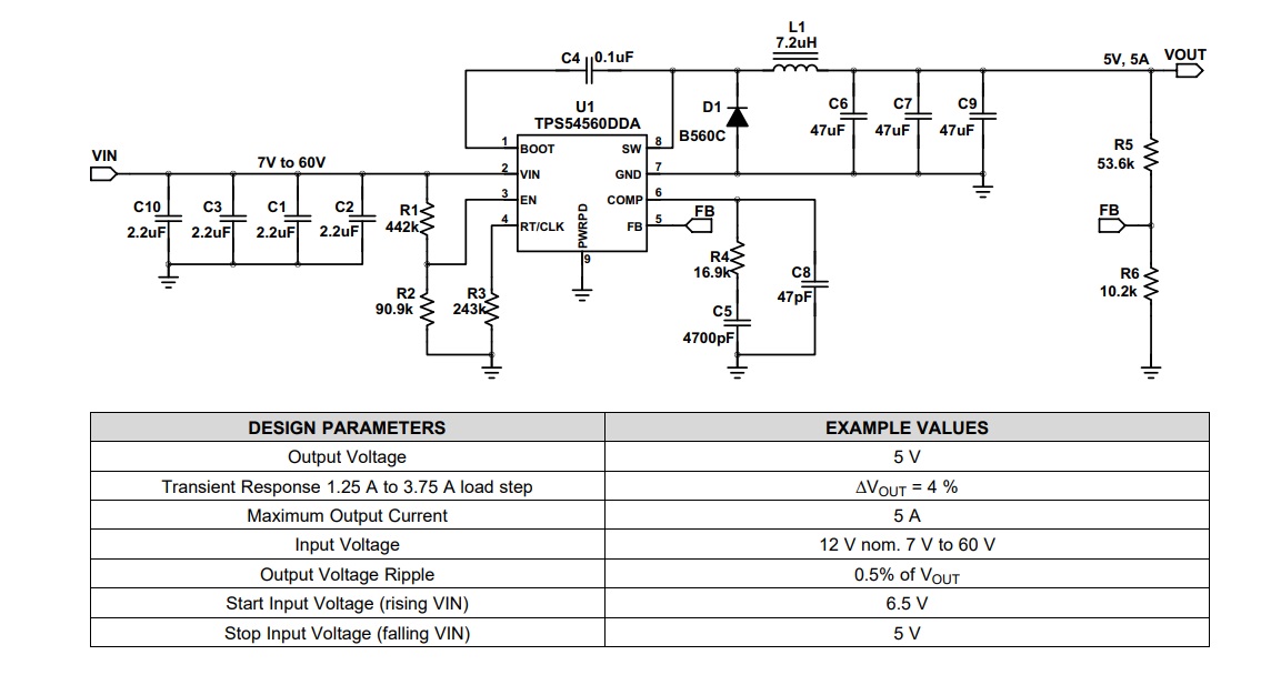
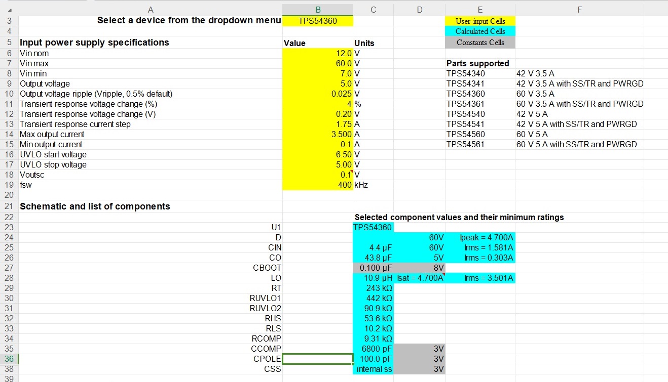
Capacitor and resistor values for 3.3V, 12V, and 24V outputs can be calculated using the TPS54360 calculator included in the appendix. The 12V output calculation reference is as follows:
(IV) ESP32-Ethernet Module
①ESP32-WROOM-32E/UE Module
The ESP32-WROOM-32E/UE module uses the ESP32-D0WD-V3, which is scalable and adaptive. Two CPU cores can be controlled independently. The CPU clock frequency is adjustable from 80 MHz to 240 MHz. Users can power off the CPU and use a low-power coprocessor to monitor peripheral status changes or whether certain analog quantities exceed thresholds. The ESP32 also integrates a rich set of peripherals, including a capacitive touch sensor, Hall effect sensor, SD card interface, Ethernet interface, high-speed SPI, UART, I2S, and I2C. The Ethernet interface integrates a 10/100 Mbps Ethernet MAC controller, which can be directly connected to an Ethernet network, supporting transmission rates up to 150 Mbps, enabling fast and stable wired network connections.
The ESP32-WROOM-32E/UE EMAC is defined as follows: IO17—EMAC_CLK: Ethernet clock signal. IO25—EMAC_RXD0: Ethernet receive data 0. IO26—EMAC_RXD1: Ethernet receive data 1.
IO27 – EMAC_RX_DV: Ethernet receive valid signal. IO19 – EMAC_TXD0: Ethernet transmit data 0. IO22 – EMAC_TXD1: Ethernet transmit data 1.
IO21 – EMAC_TX_EN: Ethernet transmit valid signal.
IO23 – EMAC_MDC: Ethernet management data clock. IO18 – EMAC_MDIO: Ethernet management data input/output.
②LAN8720A
The LAN8720A is a small, low-power, versatile 10/100Mbps Ethernet physical layer transceiver designed by SMSC (acquired by Microchip). It is designed for consumer electronics and enterprise applications. The LAN8720A has only 24 pins and supports only the RMII interface. A network structure composed of it is shown in the figure below.
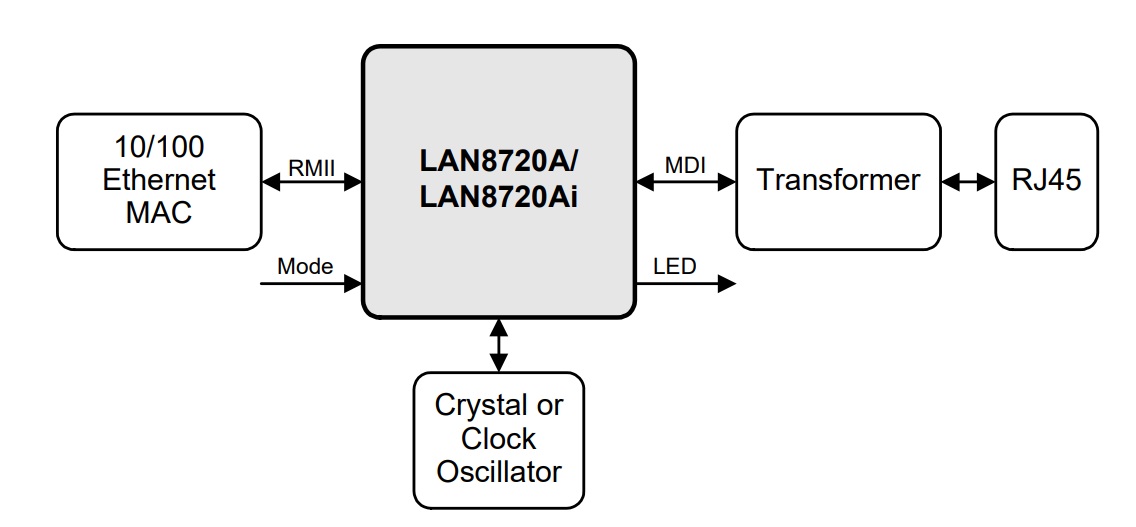
The ESP32-WROOM-32E/UE module can provide a clock signal to the LAN8720 through its clock output pin to ensure communication stability and accuracy. The LAN8720A connects to the EMAC of the ESP32-WROOM-32E/UE via RMII. A transformer is also required between the ESP32-WROOM-32E/UE and the LAN8720A. This project uses the HY931147C 100M RJ45 Ethernet connector, which has a built-in PoE rectifier circuit, effectively reducing the need for external PoE circuitry.
PHYADD0 is a bit in the LAN8720's register used to set the PHY address. The value of the PHYADD0 bit can be set to 0 or 1, allowing for different PHY addresses to be configured for communication with other devices. This function is typically used when two LAN8720s are needed.
(V) MCP23017 IO Expansion Module
The MCP23017 is a commonly used I/O expansion chip manufactured by Microchip. It can communicate with the microcontroller via the I2C bus, providing additional input/output pins. The MCP23017 features 16 configurable GPIO pins that can be used as inputs or outputs. It also includes special functions such as interrupt functionality and external interrupt pins. Using the MCP23017 can expand the input/output capabilities of a microcontroller, making it particularly suitable for applications with insufficient GPIO pins. Up to eight MCP23017 chips can be connected simultaneously via the I2C bus, expanding to 128 GPIO pins. Grounding or connecting the A0, A1, and A2 pins of the MCP23017 to VCC determines its I2C address. The following table lists these possibilities and their corresponding decimal addresses:
| A2 | A1 | A0 | I2C Address || 0 | 0 | 0 | 0x20 || 0 | 0 | 1 | 0x21 || 0 | 1 | 0 | 0x22 || 0 | 1 | 1 | 0x23 || 1 | 0 | 0 | 0x24 || 1 | 0 | 1 | 0x25 || 1 | 1 | 0 | 0x26 || 1 | 1 | 1 | 0x27 |
VII. Project Structure Diagram

VIII. Partial Program
This program is written using ESPHome, which is simple and convenient, suitable for beginners. If you want to learn in depth, I do not recommend relying on similar platforms for a long time.
esphome: name: Please enter friendly_name: Please enter
esp32: board: esp32dev
# Enable logginglogger:
ethernet: type: LAN8720 mdc_pin: GPIO23 mdio_pin: GPIO18 clk_mode: GPIO17_OUT phy_addr: 1
# Enable Home Assistant APIapi: encryption: key: "Please enter"
ota: password: "Please enter"
i2c: sda: 13 scl: 16 scan: True frequency: 800kHz
mcp23017: - id: 'mcp23017_hub1' address: 0x20 - id: 'mcp23017_hub2' address: 0x21
binary_sensor: - platform: gpio name: "MCP23017 Pin A0" pin: mcp23xxx: mcp23017_hub1 number: 0 mode: input: true pullup: false inverted: true
switch: - platform: gpio name: "MCP23017 Pin B0" pin: mcp23xxx: mcp23017_hub1 number: 8 mode: output: true inverted: false
IX. Accessories Links
UM90S Module Rack [Order Link] https://m.tb.cn/h.5PdywAD
Electrical Installation Rail [Order Link] https://m.tb.cn/h.5Od7FAZ
The 48V DIN rail switching power supply market is too murky, so I won't recommend it here. I suggest buying directly from LCSC's online store.
Ten, Diverse connection methods .

Eleven, Size definition
for easy installation and replacement: PCB length is uniformly 90mm, width is 24, 36, 48, etc. (multiples of 12; using a 12mm width can easily cause jamming during movement).


 京公网安备 11010802033920号

 2SC4015TV4/N


