Foreword:
I signed up for this training camp on a whim as soon as I saw it. I thought oscilloscopes were such high-end stuff, I had to learn them properly. Little did I know I'd get hooked so quickly, and there was no stopping me.
I made three versions of the board, starting with a replica, then struggling to find components and researching various alternatives, and finally, after verification, I succeeded on the first try! Thinking it would be a waste to just make a toy oscilloscope with this hardware,
I decided to add features. Adding features meant adjusting the pins (and rewriting the drivers – pure tears!). Sensors, RTC, buttons – I filled it up first.
For the second version, I added a casing, and it looked decent enough, but I thought there was still room for improvement, so I made two more casing versions. Luckily, the panel didn't make it in time, otherwise I would have had to make two more versions. In fact, it's practically two versions already.
I've been tinkering with the GD32, and then I got the urge to try the STM32. As of now (April 7th, 2024, 22:44:25), I'm still rushing to submit my assignment! I really don't want to miss the award! Then, I just got the STM32F103C8T6 working as an oscilloscope when I broke it. I urgently replaced it with the STM32F103C6T, but there's no time to do any more porting.
It's all the fault of the LCSC training camp! My costs! I'm hooked, and there's no way out.
In conclusion,
making a good product is really not easy; cherish every step. Thanks to this training camp for getting me into this rabbit hole, encountering all sorts of problems, and training myself in every way. Even now, I'm still typing out my assignment. Sigh, it's all tears.
My learning outcomes are as follows:
A - Based on GD32 core board:
1. Hardware design, material substitution, and verification are all OK.
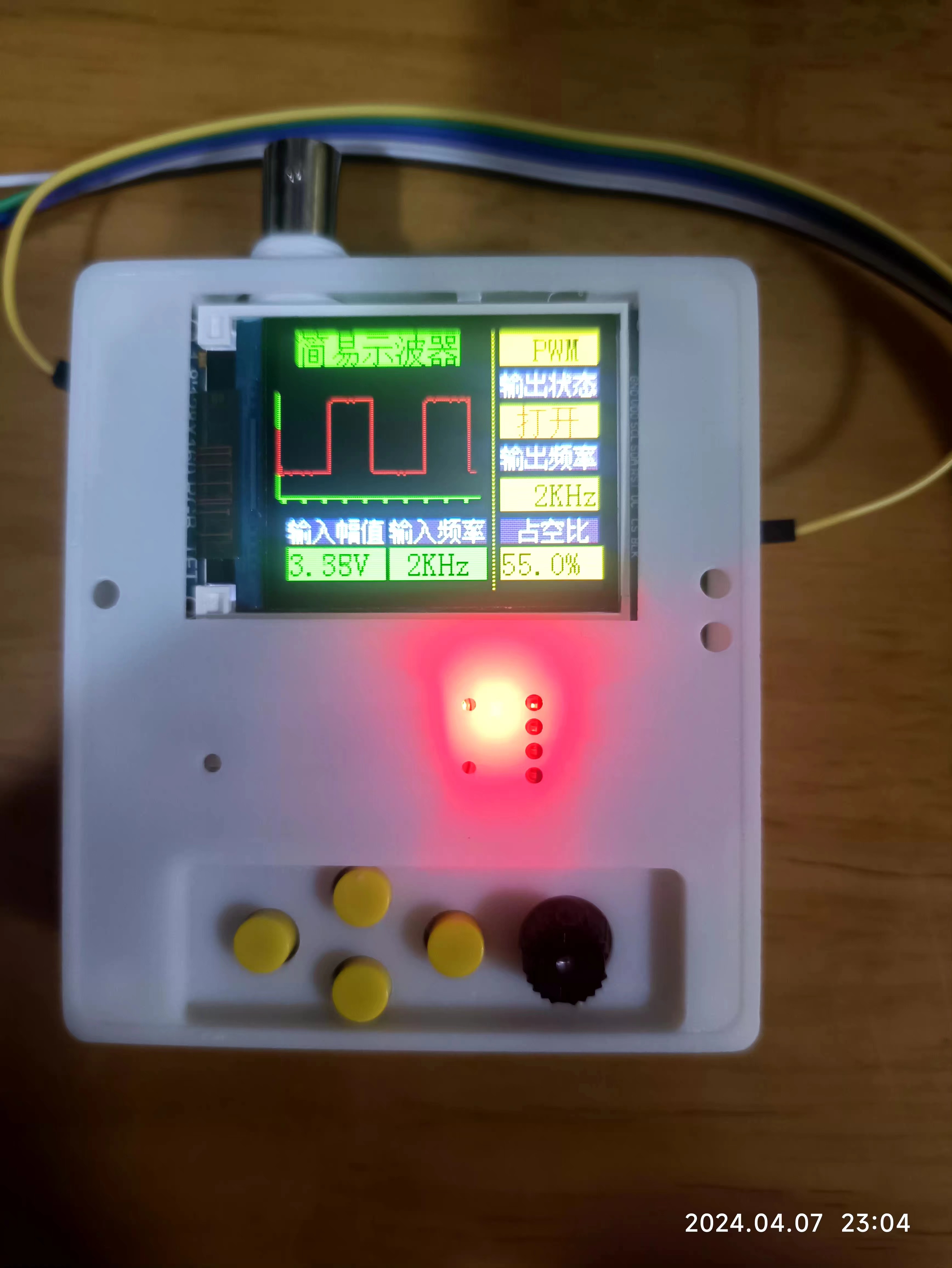
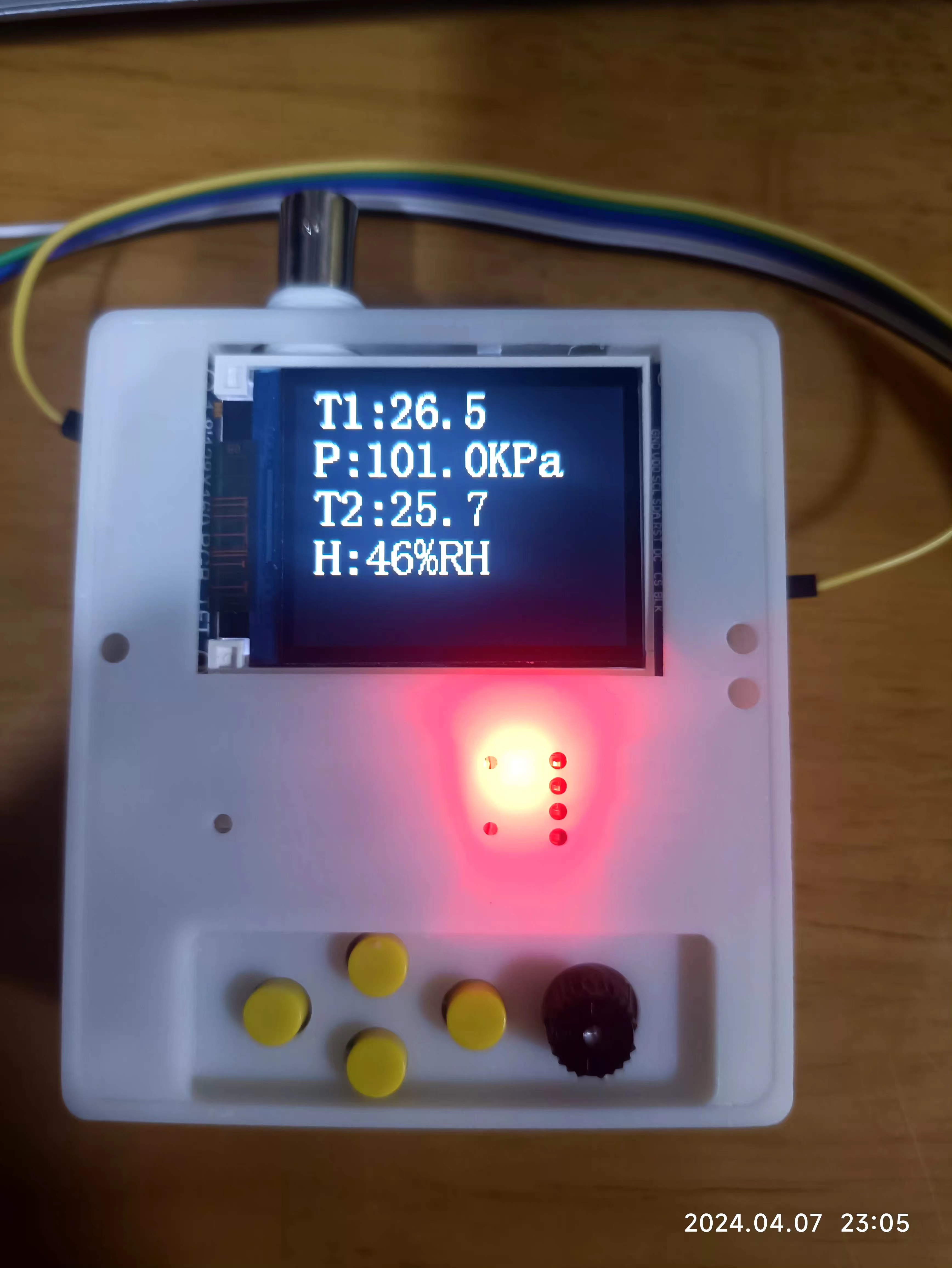
2. Software implementation includes oscilloscope, sensor driver, clock/calendar/alarm clock, and a game (Tetris). Due to resource issues, it is not fully integrated yet, but individual tests are OK.
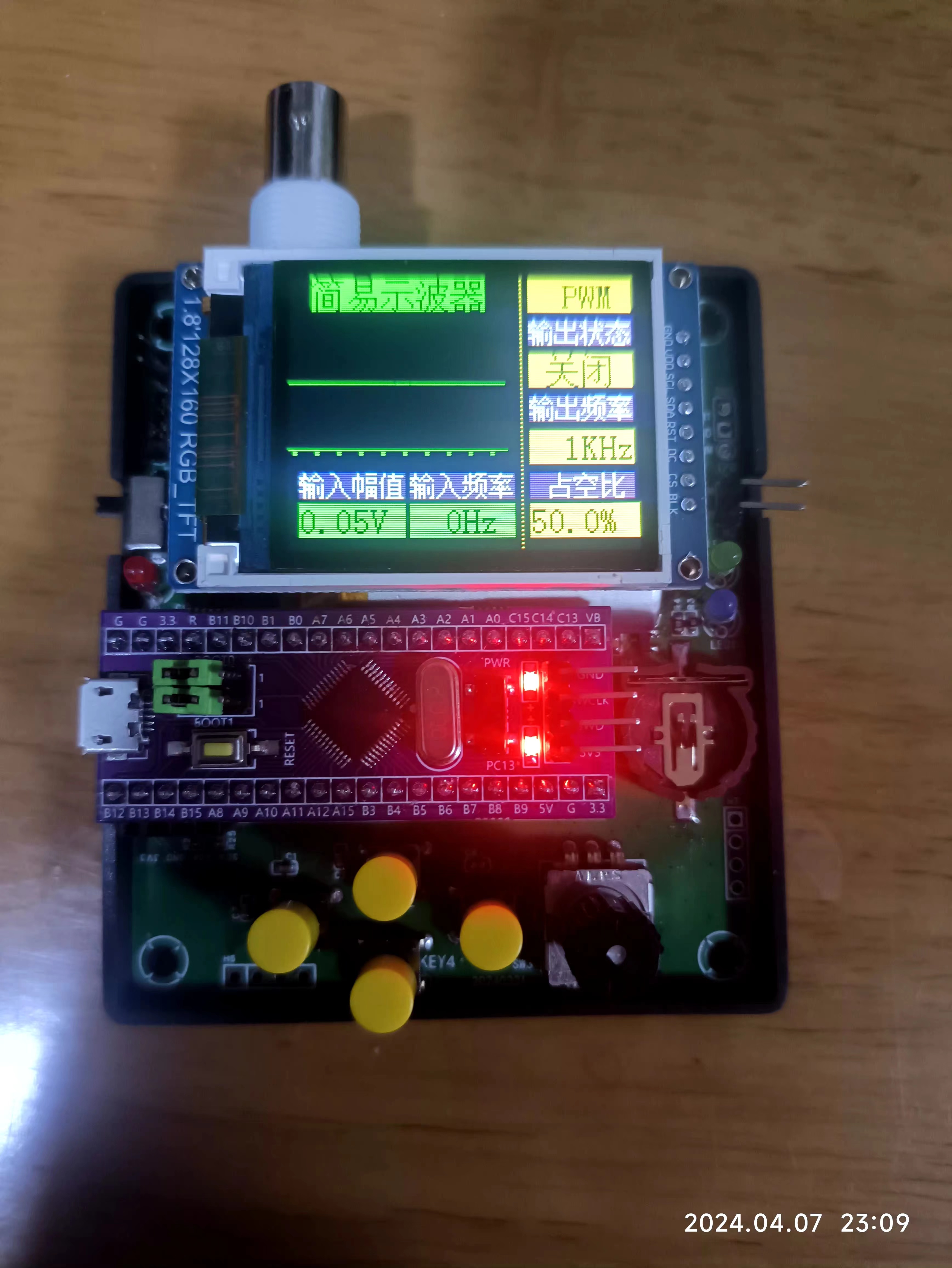
B - Based on STM32 core board
: 1. Hardware is the same as above
. 2. Software currently implements oscilloscope functionality; other functions are still being ported. Today is the last day, so I need to submit my assignment first.
C - 3D design:
1. Learning always comes at a price; I must print a physical prototype.
2. LCEDA is simple, easy to learn, and easy to use.
D - Panel design :
1. There are many videos on Bilibili; creative inspiration is needed.
2. Product thinking is required; design and experiment more.
Results presentation:
Show the effects of each. Two regrettable points: multiple functions could not be optimized and integrated together, and the panel design assignment was not submitted in time. Demo
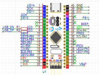
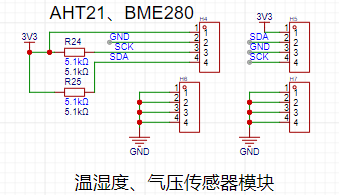
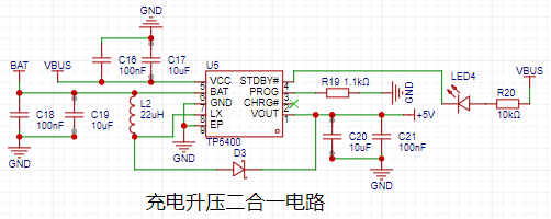
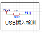
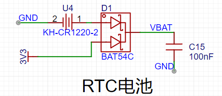
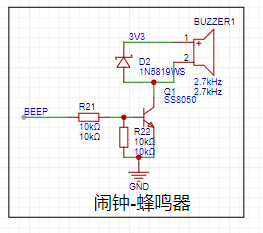
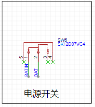
based on GD2 core board (Bilibili link) : https://www.bilibili.com/video/BV1gt421H7dW/?vd_source=24f1befd6441a33d7b240715cb07c7b5 Demo based on STM32 core board (Bilibili link) : https://www.bilibili.com/video/BV1QA4m1F77N/?vd_source=24f1befd6441a33d7b240715cb07c7b5 Hardware Design Description : This section focuses on the differences between the hardware design and the official design from the training camp. The official description of the similarities is still the best and most detailed; kudos to LCSC for this! MCU Design: To ensure compatibility with STM32 and GD32, some I/O adjustments were made, as shown below: 1- An additional button; 2- An additional USB detection I/O - PB1 3- Bring out PA9 and PA10 of the STM32; this can be used as a virtual serial port, utilizing the USB CDC function. 4- BEEP is used as the control pin for a passive buzzer. 5- The ADC is replaced with PB0, i.e., 8 channels. 6- Add one IIC channel for reading and writing sensors. 7- Bring out VBAT for use in the RTC circuit. 8- Leave an LSE pin for an external crystal oscillator to improve RTC accuracy. 9- A minor issue with the LED control pin replacement: the battery power detection I/O is not reserved. The sensor interface here features IIC interfaces for AHT21 and BMP280/BME280 for easy connection. It can be used as a smart home monitoring product. The lithium battery charging and discharging design uses the mature 5400 chip, as follows: The lithium battery charging interface uses microUSB, mainly for cost and USB pin convenience for STM32 development. The design is as follows: USB insertion detection confirms charging status. The voltage is unstable during charging; use during charging is not recommended. If using external power, it can be directly connected to the core board's USB interface. A 2.54mm pin header is provided for the lithium battery connection ; straight pins are soldered internally, and bent pins can be used if not connected. The RTC interface is designed to prevent the calendar from resetting due to power loss, and a CR1220 button battery is provided. A passive buzzer is included for convenient music playback, alarm reminders, etc. The lithium battery switch uses a physical shutdown circuit to control power consumption. Other differences : 1- All components have been changed to surface-mount materials, such as resistors, capacitors, and ICs . 2- The core IC has been replaced, as follows: 3- A button has been added , and the PCB design has been re-routed, so it will definitely be different from the official layout. However, the official layout is still referenced. The design uses LCEDA. It's free and open source. The casing design uses LCEDA. It's free and open source. Two versions were made; please refer to the design drawings and the previous physical photos for details. The panel design uses LCEDA. It's free and open source. Two versions were made, but they haven't been put into production yet; they are for reference only. The software design uses MDK, and the oscilloscope part references the official architecture and code. Thank you very much! One thing to note is that the interrupt line segmentation is the same for STM32 and GD32, so the interrupt functions and handling require special attention. Since the code isn't yet fully optimized, I won't post it here. Contact me if you need it. I'll share the code after I've improved the product. Now, you must submit your work!


Completed at 23:59:43 on April 7, 2024.


 京公网安备 11010802033920号

 MTXV6E9AD


