This is a mini soldering furnace,
small in size, low in cost, and suitable for amateur, low-intensity use by electronics enthusiasts. It is powered by a Type-C or 12V-DC power supply. The hardware

schematic is available at:
https://oshwhub.com/code504/mi-ni-xi-lu
(Hardware updates will primarily be made on oshwhub; unless there are special circumstances, Gitee will only update the documentation, not the project files). A video demo is available at
: https://gitee.com/dma/mini_solder_furnace
(Video demonstration:
https://www.bilibili.com/video/BV1kj41127hD/ )
**WARNING:
** Please exercise caution during use. Beware of burns from high temperatures!
Only one of the two power connectors can be used for power supply. Simultaneous use of both power supplies is strictly prohibited and may damage the power supply. You are solely responsible for any consequences.
Bill of Materials
(BOM) | Component Name
|
Quantity |
Description
| Unit Price | |--- |---|---|---|---| |
Ceramic Heating Plate
| 1
| Depends on the situation; a resistance of 7 to 10 ohms is recommended.
| 8.00
| | K-type Thermocouple
| 1 |
Buy the type with a small solder point at the head; do not buy rod-shaped, screw-shaped, or other special shapes. |
1.50 |
The resistance of the ceramic heating plate must be selected according to the actual situation. Assuming a 12V 2A power supply, to ensure that the peak power of the power supply is not exceeded, the resistance of the heating plate should be selected as 7 ohms, with a power of less than 21W. This heating plate, when used with a 20V 3A power supply, has a power of approximately 57W, which does not exceed the output limit of a 65W charger. If a 10-ohm heating plate is used, it is only recommended for use with a 20V 3A power supply. If used with a 12V 2A power supply, the power is less than 15W, and even with insulation, it will take a long time to melt, resulting in very low heating efficiency.
For other electronic components, please open the LCSC open-source project and export the BOM for reference.
Hardware Category
Name
Quantity
Description
Unit Price
Copper Pillar
3
Specification M3, Length 10mm
0.10
Copper Pillar
4 Specification
M3, Length 15mm
0.15
Copper Pillar
4 Specification M3
, Length 20mm
0.20
Screw
4
Specification M3, Length 5mm
0.05
Nut
4
Specification M3
0.01
Washer
1
Inner diameter 20mm, outer diameter 37mm, this size is a standard part (if you can buy a non-standard part with an inner diameter of 20mm and an outer diameter of 30mm, that would be better)
0.20
Knob
1
Inner diameter 6mm, outer diameter 10mm, maximum not exceeding 12mm. Each one costs only a few cents, and they are usually sold in batches of 10.
0.50
aluminum silicate insulation cotton
1
, choose 1mm thickness, usually sold by the meter, about 8 yuan per square meter, 100 per square meter is not a problem.
8.00
copper pipe plug
1
4 cents, external thread
1.50
panel printing
1
such a small panel can print at least 30 at a time.
25.00
Production instructions
Please read carefully before making it. I have almost encountered all the pitfalls
. The structure is very simple. Two main boards and one fixing board can be assembled as shown in the figure. Here are some details and places where mistakes are easy to make.
Buy the kind of copper plug with a flat bottom. The picture below is an incorrect example. I did not pay attention and bought one with a raised printed bottom. You can only manually grind

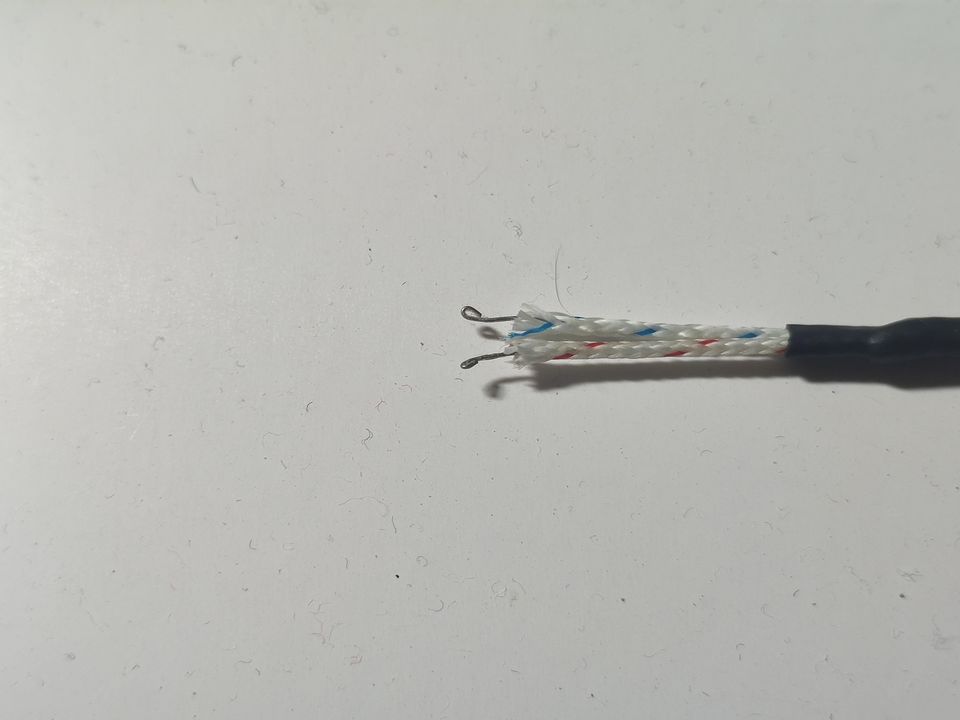
the two leads of the thermocouple, especially the positive lead, which is difficult to be wetted by solder (commonly known as not being soldered). It is easy to fall off when soldered using conventional methods. You can do it like me, make a ring at the wire end, and then embed the ring in the solder. The shape of the solder after cooling will fix it. Using screw posts for fixing is also an option, but currently, making a ring is probably the simplest method.
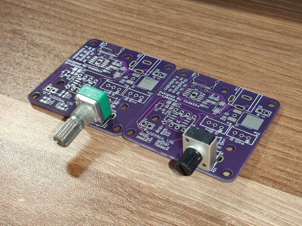
The motherboard has pre-drilled pads for RV09 and RK097 potentiometers. The installation effect of the two potentiometers is as follows:
The heating element and thermocouple wires can be passed through any suitable hole on the circuit board.

The motherboard has three screw holes for fixing the plugs. Maximize the use of every inch of space on the motherboard

by cutting appropriately sized insulation cotton, approximately 5mm thick. Place the ceramic heating element and K-type thermocouple on top of the insulation cotton. The thermocouple should not be directly against the heating element; leave a 1mm gap, otherwise the measured temperature will be too high.
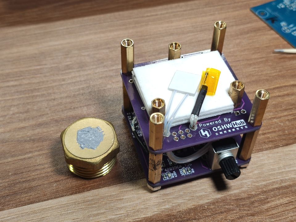
Apply a suitable amount of silicone grease to the thermocouple, place the copper plug on it, and fix the copper plug with a washer. The washer is fixed with a copper post, with a copper post height of 10mm.
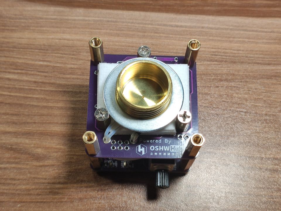
If you buy a washer with an inner diameter of 20mm and an outer diameter of 37mm, you need to manually grind the grooves corresponding to the three screw holes. Choose a material like galvanized iron; never choose stainless steel, as stainless steel is expensive, hard, and difficult to grind. If you buy a 20mm inner diameter and 30mm outer diameter gasket, you don't need to do any processing; just install it directly.

The holes on the mounting plate are specially designed to be larger than the copper plugs, and you need to pad the edges with 2 to 3mm thick heat insulation cotton. The final product is shown in
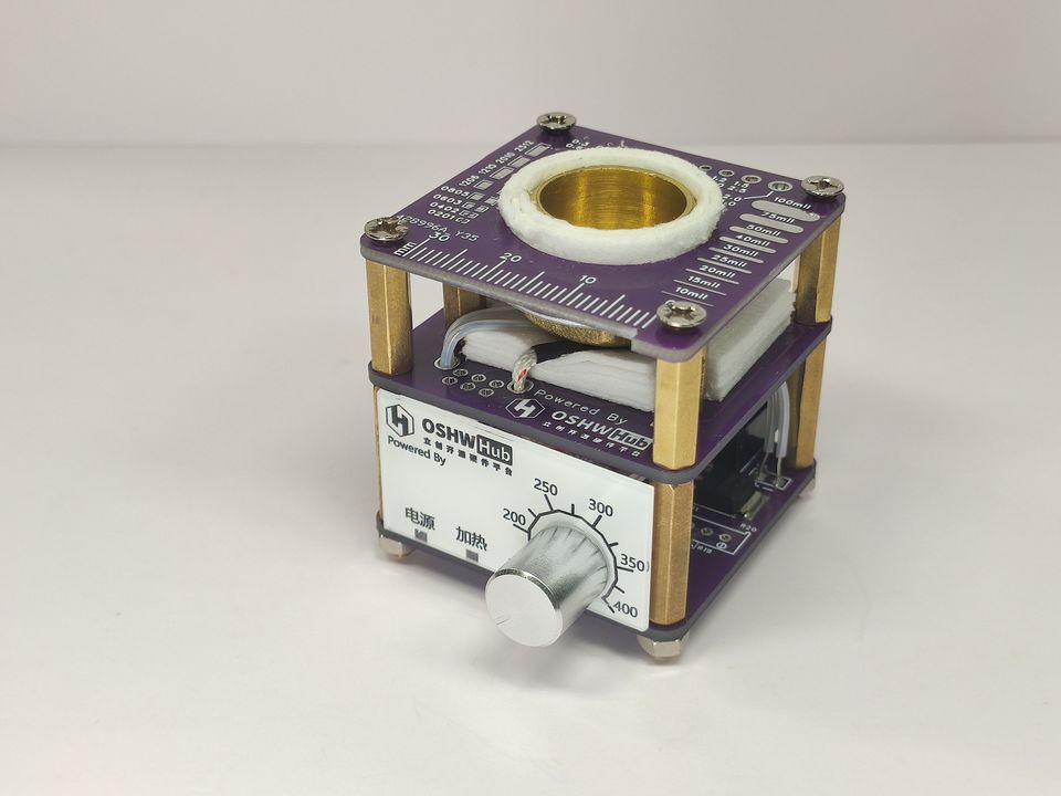
the panel below. Due to an error, the arc became a zigzag line, which has now been corrected. The working principle of
FYI
heating devices is similar. If you are interested, you can draw an aluminum substrate and modify it into a mini heating platform. Please also adhere to the open source license when modifying it!
Working principle
: The working principle of the solder pot is similar to that of a hot air gun and a temperature-adjustable soldering iron. It controls heating by comparing the actual temperature with the set temperature.
The temperature sensing element is a K-type thermocouple. You can find the following table in the datasheet. You can find the temperature by measuring the voltage across the thermocouple.
The TL431 is an adjustable precision voltage regulator used to provide a 2.5V reference voltage.
The first operational amplifier is composed of several external circuits forming a circuit that combines a voltage comparator and a non-inverting Schmitt trigger.
In the voltage comparator section, the positive input terminal is connected to the positive terminal of the thermocouple via an external circuit, and the inverting input terminal is connected to potentiometer R21. When the measured temperature is higher than the set temperature, the output is high; otherwise, the output is low.
The temperature setting circuit consists of a 2.5V voltage source and resistors R15 to R21. Using the voltage divider formula for series and parallel resistors learned in second grade, the voltage across each resistor can be calculated. Here, it's necessary to select appropriate resistors to keep the voltage at the middle pin of R21 within a reasonable range.
For example, if the desired temperature range is 150°C to 400°C, consult the K-type thermocouple datasheet to find the corresponding voltage value. This means the adjustable range of the voltage at the middle pin of R21 is 6.14 to 16.4 millivolts.
Assuming we initially set R19 to 220 ohms, then R15 + (R17 in parallel with R21) + R19 = 2.5/0.00614 * 220 = approximately 89577 ohms. (R17 in parallel with R21) = 89576/(2.5/0.0164) - 220 = approximately 368 ohms. Therefore, R15 = 89576 - 220 - 368 = 88988 ohms. Theoretically, 91K and 390 (390 in parallel with 10K is approximately 375) resistors would be most suitable, but I don't have them on hand at the moment. Therefore, in the schematic, I approximate the resistor values as 100K and 470 (470 in parallel with 10K is approximately 449).
Since fixed-value resistors are usually not the exact values we calculate, three fine-tuning resistors, R16, R18, and R20, are reserved here. These fine-tuning resistors can be omitted if precision is not a concern.
To avoid repeated oscillations and heating near the target temperature, R13 and R14 form a Schmitt trigger, a bistable trigger circuit with hysteresis comparison functionality. It can be used as an integer filter circuit to improve stability and anti-interference capabilities. Here, a non-inverting Schmitt trigger is used. Taking the parameters in the diagram as an example, with a 20V power supply, the threshold voltage is approximately 0.94 mV, equivalent to a temperature fluctuation range of 24 degrees Celsius.
That is, when the input voltage is higher than the set voltage plus 0.94 mV, the output is high; when it is lower than the set voltage minus 0.94 mV, the output is low; and when it is between the set voltage plus and minus 0.94 mV, the output state remains unchanged.
However, the above circuit is exactly the opposite of the desired control logic. Therefore, the second operational amplifier uses a voltage comparator structure to achieve the switching function. The positive input is connected to a 2.5V reference voltage source, and the inverting input is connected to the output of the first operational amplifier. The inverted signal drives the NMOS transistor for heating control.
This is a simple explanation of the working principle of the solder pot. For a deeper understanding of operational amplifiers, please refer to books such as "Circuit Design Based on Operational Amplifiers and Analog Integrated Circuits."
Q&A:
Why not use NTC or PTC thermistors?
Two reasons: Thermistors are non-linear components, making simple linear control with operational amplifiers difficult; the operating temperature limit of thermistors is generally no more than 150 degrees Celsius, unsuitable for the working environment of solder pots.
Why not use PTC heating elements?
The maximum heating temperature of a typical PTC heating element is no more than 300 degrees Celsius, while the design operating temperature of a solder pot can reach 400 degrees Celsius. Furthermore, high-temperature PTC heating elements are difficult to purchase. Considering all factors, using small ceramic heating elements is more suitable.
Can PMOS transistors be used for the output?
The main reason is that PMOS transistors with the same parameters are more expensive than NMOS transistors. If a PMOS transistor must be used, the output signal of the first operational amplifier can directly control the PMOS transistor without going through the second operational amplifier. The disadvantage is that the heating indicator light is reversed.
How to distinguish the positive and negative terminals of a thermocouple?
Look at the thermocouple's temperature gauge, then use your brain (doge.jpg).
Why add insulation?
The softening temperature of FR4 board is approximately 130 degrees Celsius, what do you think?
Why not design a shell?
Of course we did! Actual testing revealed that 3D-printed shells made of heat-sensitive materials like PLA, ABS, and nylon would soften and deform after prolonged use. The solution was to add a layer of hollow motherboard with copper pillars for insulation. This changes the current structure from [motherboard - copper pillar - motherboard (shell covers this layer) - copper pillar (heating components placed in this layer) - fixing plate] to [motherboard - copper pillar - motherboard (shell covers this layer) - copper pillar - motherboard - copper pillar (heating components placed in this layer) - fixing plate]. The downside is that it's taller, more prone to tipping, less safe, and requires three motherboards; five prototypes are needed to make one unit. Those with deep pockets can use a CNC shell.
Couldn't we add a diode to protect against dual power supply scenarios?
Because I'm lazy! I believe anyone who can build this solder pot has basic circuit knowledge and wouldn't make such a basic mistake as dual power supply. Of course, you can modify it yourself if you want. I considered the
discrepancy between the temperature marked on the panel and the actual temperature
during the design process. To use resistors with common resistance values as much as possible, some precision had to be sacrificed. The adjustable temperature range calculated using the current schematic is 133 to 405 degrees Celsius, which is basically the same as the temperature marked on the panel. The solder pot does not need very precise temperature control. Those with obsessive-compulsive tendencies can replace the resistors with more precise ones and add fine-tuning resistors for adjustment.
Why can't my charger trick
me into outputting 20V? Is it my fault? Ask your charger manufacturer. Especially since many mobile phone chargers use proprietary protocols for their 65W output, I won't comment on these chargers; just understand the implications. Do
I sell finished products? No,
I do not sell finished products and have no plans for mass production. Any channel selling the same mini solder pot is not mine; please be careful! All materials are open source; if you are interested, please build it yourself.
Is there a discussion group?
No, please leave a message or send a private message if you have any questions during the building process. Please be mindful of online etiquette when asking questions. If you are unfamiliar with etiquette, please visit https://github.com/ryanhanwu/How-To-Ask-Questions-The-Smart-Way to learn. Don't ask questions like "Are you there?", and definitely don't ask questions whose answers can be found in the documentation.


 京公网安备 11010802033920号

 12105C104K4Z4A


