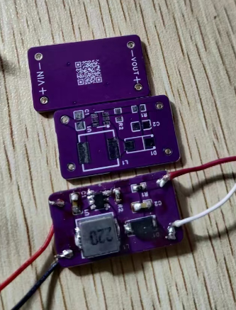
1. The schematic is drawn according to the typical application circuit of SX1308.
2. According to the datasheet, SX1308 and MT3608 are pin-to-pin interchangeable.
3. The SX1308 IC has been actually fabricated. A single 3.7V 18650 battery can boost the output to 12V and drive a 12V 0.56A graphics card fan.
4. The current module has a fixed output of 12V, regardless of the input voltage of 3.7V or 8.4V.
: Vout = Vref * (1 + R1/R2).
R2 is recommended to be 10MΩ, or determined based on available materials, ensuring the ratio is correct.
. 5. This IC generates significant heat when the voltage difference is large. Take care to avoid burns.
The USB 3.0 port is split into a USB 2.0 port and a USB 3.0-only port. The USB 3.0-only port is not backward compatible with USB 2.0. Both output ports can be used simultaneously.
The USB 3.0 output is split into one USB 2.0 port and one USB 3.0-only port. The USB 3.0-only port is not backward compatible with USB 2.0. Both output ports can be used simultaneously. The cost is similar to replicating a JLCPCB PCB board; you can buy a few connectors on Taobao – five single-layer connectors and five double-layer connectors cost a total of 6 yuan. The capacitors don't need to be soldered; it doesn't matter. The project uses two PCB boards, one with one USB 3.0 and one USB 2.0 output, which is more expensive and has slightly lower compatibility. The double-layer connector output solution is recommended. If you want a two-connector output solution, please refer to another project on my homepage.
I tried using the 5.8G antenna array V2.0, which is offered as a buy-one-get-five-free deal on Taobao.
Disclaimer:
This design is for tinkering and technical learning purposes only, and is not recommended for use in a production environment.
The author will not be responsible for any losses incurred as a result.
It is not recommended to build this without any VNA.
Using a two-layer JLC board offers no impedance guarantee, so your measured results may deviate from the expected performance; this is normal.
Chip inconsistency may be poor. It's amazing to find four LNAs salvaged from all over the country on the same board (not really).
Due to the poor high-frequency loss of the free materials, I still recommend purchasing proven antennas from reputable brands. (Advertisement space for rent (x
antenna belongs to the religious field, I respect and tolerate your beliefs, and I also hope you can tolerate others who are different from you, thank you.
Open source license: CC BY-NC-SA 4.0
What is this mess?
First you need to read the mess of version V1.0:
https://oshwhub.com/libc0607/5g8_cheap_antenna_4to1_v1p0_rel
I won't repeat it, I will continue from V1.0 here.
In order to minimize the impact of board loss on the received signal, I tried to push it with LNA as close as possible to the antenna port. It
is roughly the idea of active antenna array, but since this version does not have transmit and receive switching, it can only be used for receiving.
This version only supports the receiving
design
LNA. Here I chose SKY65981, mainly because 1. small footprint, 2. acceptable NF, 3. 2.4~2.5GHz gain is not greater than 0dB - at least it will not make things worse, 4. fried version only 2 yuan per piece
1.4 cents) The microstrip line structure and reflector structure are completely identical to V1.0.
An EC190708 is used with a button for LNA enable switching. This allows manual switching to bypass mode at close range to prevent your homemade amplifier from overpowering the LNA.
Type-C power is used, but it seems I made a mistake. You can modify the interface or use a jumper wire
to connect the LNA power supply on the back of the board with a 1.25mm jumper, as shown in the picture.
BOM
PCB: Two layers, 0.8mm total thickness.
Excluding the PCB and all components (note—different from V1.0 components), you will also need:
a five-in-one antenna (wire length >= 30mm). However, longer wires will result in losses.
A 200mm x 200mm x 1mm aluminum plate is needed for the reflector. I bought two
M3x3 screws (free shipping), 10
M3x12 (length may need fine-tuning), 5
M1.0x3 screws, and 8
M1.0 screws for 3.x yuan on Taobao. Nuts, 8 pieces
; 1.25mm 2p 10cm connecting wires, 4 pieces (note the wire sequence!) (New in V2.0).
Using a deep-fried LNA (unit price about 2 yuan), the total cost comes to about 20 yuan. In
addition to common electronic building tools, you will also need the following tools:
electric drill/hand drill,
1.0mm/3.0mm drill bit that can drill aluminum plates
, sandpaper or other similar materials . It was too hot outside (?), so I
tested
it indoors. A6 network card + app reception, MCS1. In short, it is several dB stronger than V1.0 in the same location, and much stronger than a single original antenna.

PDF_Buy One Get Five Free: An Attempt at a 5.8G Antenna Array V2.0.zip
Altium_Buy One Get Five Free 5.8G Antenna Array Attempt V2.0.zip
PADS_Buy One Get Five Free 5.8G Antenna Array Attempt V2.0.zip
BOM_Buy One Get Five Free 5.8G Antenna Array Attempt V2.0.xlsx
92177
SSC338Q-IMX415-OpenIPC
SSC338Q IMX415 OpenIPC Solution Verification Board
SSC338Q IMX415 OpenIPC Solution Verification Board:
Open Source Digital Video Transmission OpenIPC Hardware Solution

PDF_SSC338Q-IMX415-OpenIPC.zip
Altium_SSC338Q-IMX415-OpenIPC.zip
PADS_SSC338Q-IMX415-OpenIPC.zip
BOM_SSC338Q-IMX415-OpenIPC.xlsx
92178
USBToUART
51 microcontroller download board
It can be equipped with CH340C/CH340G/CH340T, and features an onboard 3.3V regulator, with options for ASM1117 and XC6206. The 5V and 3.3V outputs have latching switches, and there are ample reserved GND pins.
PDF_USBToUART.zip
Altium_USBToUART.zip
PADS_USBToUART.zip
BOM_USBToUART.xlsx
92179
CH571F Development Board
CH571F Minimal System Version
The CH571F/CH573F development board features an onboard Type-C port, PCB antenna, and all I/O pins with 50mil spacing, allowing it to be soldered onto a functional board as a module.
PDF_CH571F development board.zip
Altium_CH571F development board.zip
PADS_CH571F development board.zip
BOM_CH571F Development Board.xlsx
92180
English vocabulary learning tool
Create a handy tool for learning English words using ESP32 and HLK-V20.
Project Name:
English Vocabulary Learning Tool
Project Requirements:
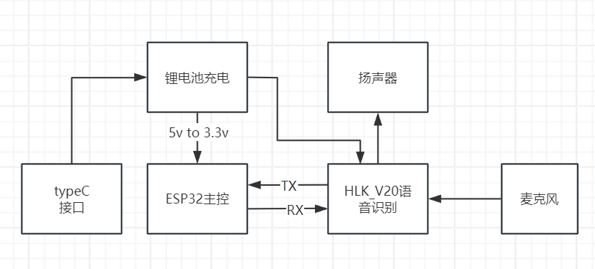
This tool is primarily for English reading and listening. Therefore, it utilizes an ESP32 and HLK_V20 to create a simple tool (a little toy) for reading and listening to words.
The main design includes four functions: sequential learning, random learning, sequential recognition, and random recognition.
MQTT allows setting the learning mode, maximum random number value, and recording learning duration and the number of words learned during testing.
Overall Design Scheme Block Diagram
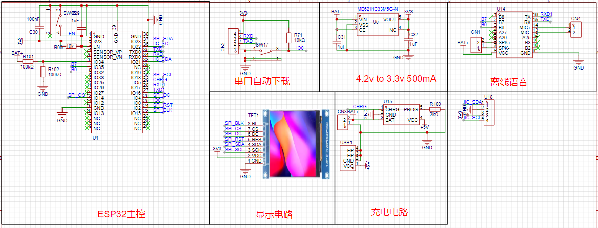
Schematic Diagram Design Description
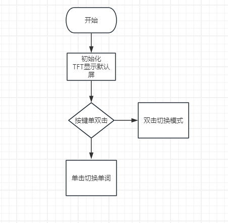
Software
Description: The software is nothing special; it mainly uses the Arduino IDE for development and related libraries.
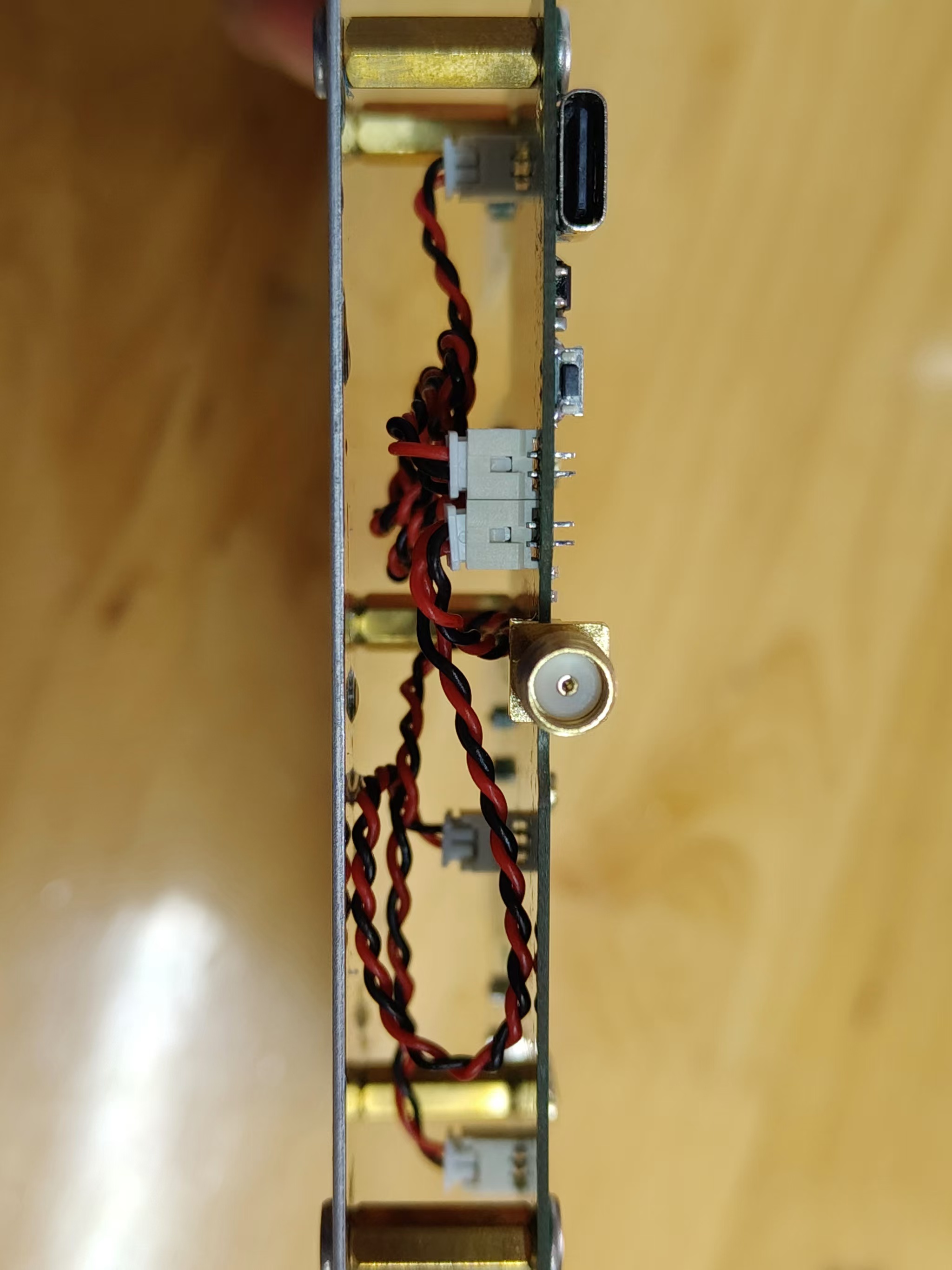
Physical Demonstration Description

Notes
: For the main hardware, the serial port output of the voice module should ideally include a header and footer to prevent misinterpretation and inconsistent output.
Voice recognition broadcast.mp4
Identify 1.mp4
Recognize.mp4
PDF_English Vocabulary Learning Tool.zip
Altium_English Vocabulary Learning Tool.zip
PADS_English Vocabulary Learning Tool.zip
BOM_English Vocabulary Learning Tool.xlsx
92181
GL3224 Card Reader - Dual Card Dual Reading
This chip, based on the QFN-48 packaged GL3224, supports dual-SIM dual-read functionality.
Only this packaged GL3224 chip supports this; the 32-pin package only supports single-SIM single-read!
There are three versions: one with an A-port, one with an A-female connector, and the last one with a C-port male connector.
PCB design instructions:
Use the 3313 structure; the lamination order is in my files (I don't know why it's not showing up here at LCSC).
Impedance control is 20% (free; you can pay for 10%), otherwise you can't create a USB 3.0 speed board. PCB
thickness is 1.2mm.

Schematic diagram:
Appearance inspiration: USB 3.0 card reader, based on the GL3224 solution, with SD and TF card slots - LCSC open-source hardware platform (oshwhub.com).


Dual card insertion is as follows:
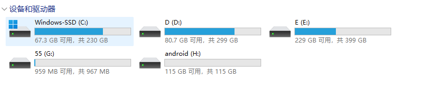
When ejecting, you can select only one card for speed
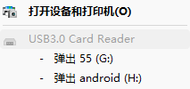
testing:
TF card, Kioxia G2 128G version

GL3224 chip, the official 1532 firmware supports USB 3.0, no firmware upgrade required!!! (Only specific versions of Windows 10 require an upgrade).

The reason an upgrade is needed to "support" USB 3.0 is mentioned in the official UGREEN announcement.
The chip was bought for 4 RMB from Baoxiang Electronics on Taobao, and everything works perfectly. Remember to buy two extra to avoid overheating and damaging them during soldering.
My soldering process: When
soldering chips with a hot air gun, first apply solder to the chip's pins using a bent-tip soldering iron. Do not apply
solder to the large grounding pad in the middle of the chip. Heat the chip to 350 degrees Celsius for ten seconds, then apply solder paste along the pad's lead using a syringe. Apply a little solder to the large grounding pad in the middle as well.
Place the chip on top and heat it again. After the solder paste melts, press the chip down with tweezers to prevent poor soldering of any pins.
Then remove the hot air gun and wait for the solder to cool and solidify. Then use the soldering iron to run it along all four edges of the chip (you can place it on the soldering machine first for easier touch-ups) to ensure there is no solder joint. Do
the same for other components: preheat the hot air gun, apply solder paste, then place the capacitors and resistors and heat them again (do not place LEDs at this time; place them last to avoid damaging them).
Usage:
It takes five or six seconds for the computer to recognize the chip. If you are using a camera memory card for long-term copying of materials, please purchase a heatsink on Taobao.
PDF_GL3224 Card Reader - Dual Card Dual Reader.zip
Altium GL3224 Card Reader - Dual SIM Dual Reader.zip
PADS_GL3224 Card Reader - Dual SIM Dual Reader.zip
BOM_GL3224 Card Reader - Dual SIM Dual Reader.xlsx
92182
electronic


 京公网安备 11010802033920号

 PTT111-4422A-B4104


