Project Description:
This project was designed by Lei Chaolin of the New Energy Application Laboratory at Hunan University of Science and Technology. This project is provided for learning and exchange purposes only. Replication is welcome, but commercial use is strictly prohibited.
Welcome to join the QQ group 458720579 for discussion. Your likes and favorites are my motivation for the next project!
For any questions, please join the QQ group for consultation!
Open Source License

Project Functionality
Input: DC48V-72V;
Maximum Output Power: 2000W;
Output:
AC220V sine wave x2;
USBDC x2 (maximum 100W);
Power, Capacity, and Output Voltage Display;
Each AC output port has an independent switch for shutdown control;
Protection Circuit:
Short circuit protection;
Overload protection;
Temperature protection;
Battery overcharge protection;
Surge protection; Reverse connection protection
;
Voltage regulation protection;
Project cost is approximately 500 RMB.
Project Attributes:
This project is being publicly disclosed for the first time and is my original work. This project has not won any awards in other competitions.
Project Schedule:
July 2023: Project started;
August 2023: Main circuit designed;
September 2023: PCB completed;
October 2023: Successful debugging.
Design Principles:
First, we analyzed the project requirements and found that it was a wide-range input inverter, with voltage from 48V to 72V, and it also needed to support battery power. When mains power is available, it supplies power through the mains; when the mains power fails, the inverter needs to operate immediately.
Normally, when mains power is available, it needs to charge the battery. This is essentially a UPS (Uninterruptible Power Supply). Most commercially available UPSs use a single-range input and employ DAB (Dynamic Amplifier) active resonant current for bidirectional current flow, allowing the battery to both supply power and charge.
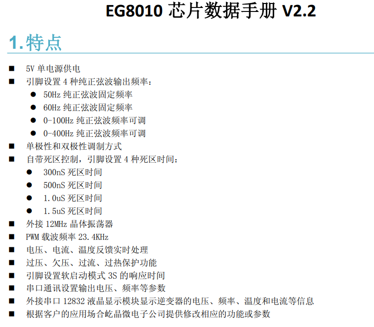
However, according to the chip datasheet, when charging the battery, the PFC boost voltage is a maximum of 450V, and after resonant (4:30) through the transformer LLC to the battery, it reaches 69V. We know that a 72V battery needs to reach 80V to fully charge, so the EG8026 chip is not suitable for our needs.


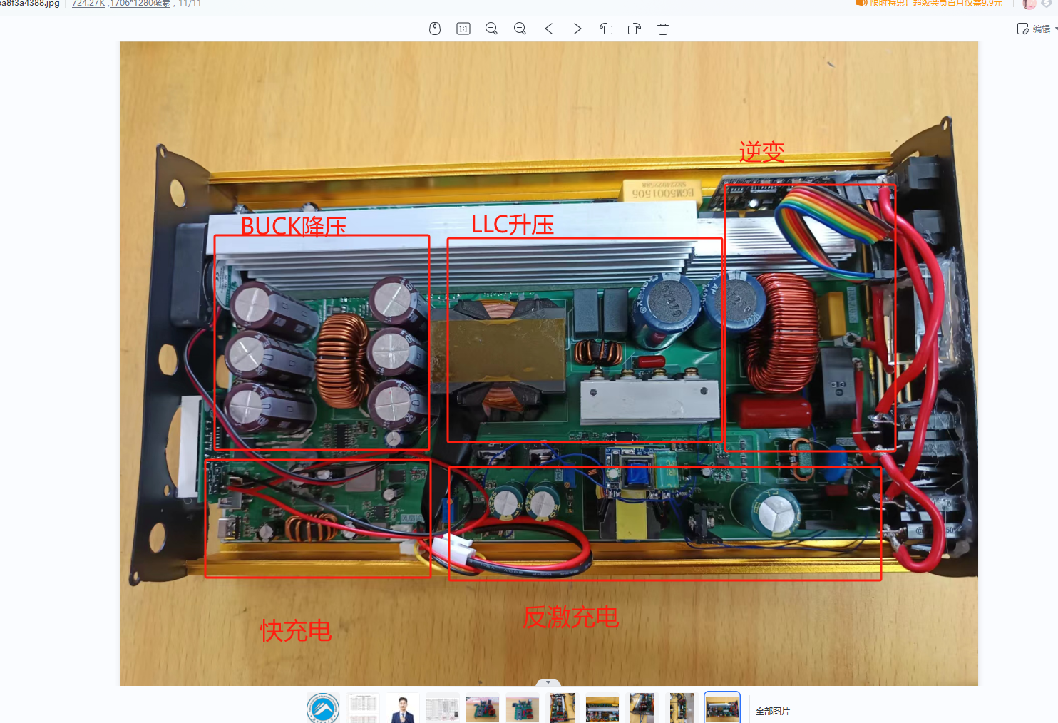
At this point, a charging circuit is needed to charge the battery separately. Therefore, my topology is BUCK+LLC+SPWM+FLYBUCK.
Below is my topology diagram.

Batteries ranging from 48V to 72V are uniformly stepped down to 48V via a synchronous BUCK circuit, and then boosted to the 350V DC bus VBUS voltage via LLC resonant soft-switching technology, and then inverted via SPWM.
This perfectly solves the problem of wide-range input voltage, supporting a maximum input voltage of 100V.
The charging section uses a FLYBUCK circuit for constant current charging with a power of 200W and an output voltage of 48V-80V.
The following is a detailed explanation of the circuit used:
1.1 Primary EG1163S Synchronous Buck Circuit

The four input MOSFETs are reverse connection protection circuits. After that, there are three 1000uF/100V black diamond capacitors connected in parallel. Then, the synchronous BUCK circuit is used to step down the voltage through the upper and lower transistors of the two MOSFETs connected in parallel, with a current-limiting resistor in the middle for overcurrent protection. Due to a synchronization issue discovered during EG1163S debugging, an additional Schottky high-current diode (U4) was added to distribute some of the current. The BUCK output also uses three 1000uf/100V high-capacity capacitors. The chip's external circuitry is simple yet powerful. If instability occurs, adjust the loop compensation feedforward capacitor, adding an appropriate amount, such as 100nF, and then check if the subsequent output is normal.

1.2 LLC Resonant Circuit
The LLC resonant boost section uses the EG1611 chip. This chip can output a fixed-frequency PWM signal, and the frequency can be adjusted via resistor R43. The frequency needs to match the resonant cavity frequency of the LLC stage to achieve soft-switching technology, greatly improving efficiency.
The subsequent stage uses open-loop voltage control. When the output voltage exceeds 450V, feedback protection is implemented. The EG2132 is the gate driver. The transformer was purchased from Taobao; the 48V 2KW transformer with a leakage inductance of 18uH can be found in Yijing Micro's Taobao shop. A 650V 10A diode can be used as the rectifier diode. R24 and R26 are discharge resistors, used to discharge any residual charge in the capacitors.

1.3 Inverter Circuit
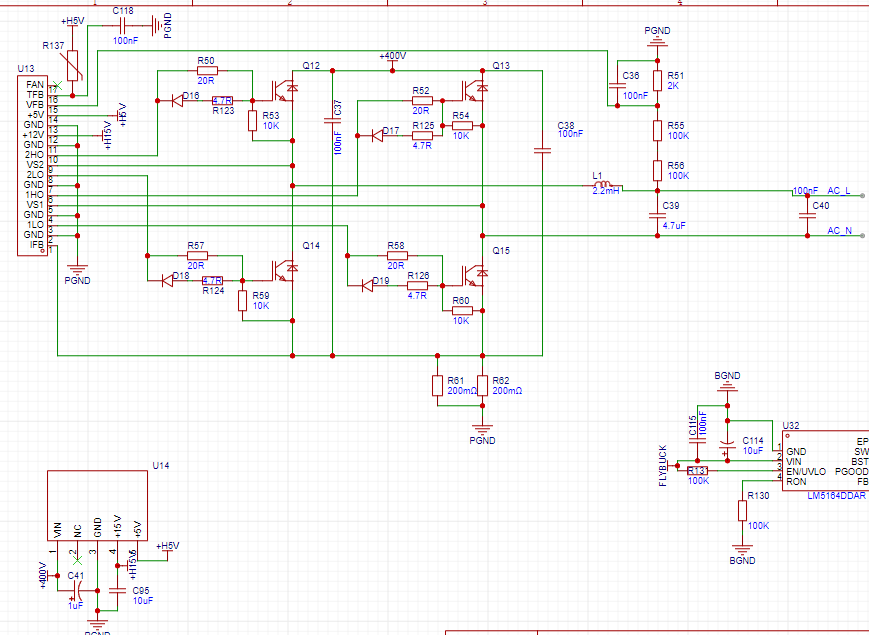
The inverter circuit consists of an EG8010 small board and four IGBTs. MOSFETs can also be used, but they need to be at least 20A current rating and are packaged in TO-247.
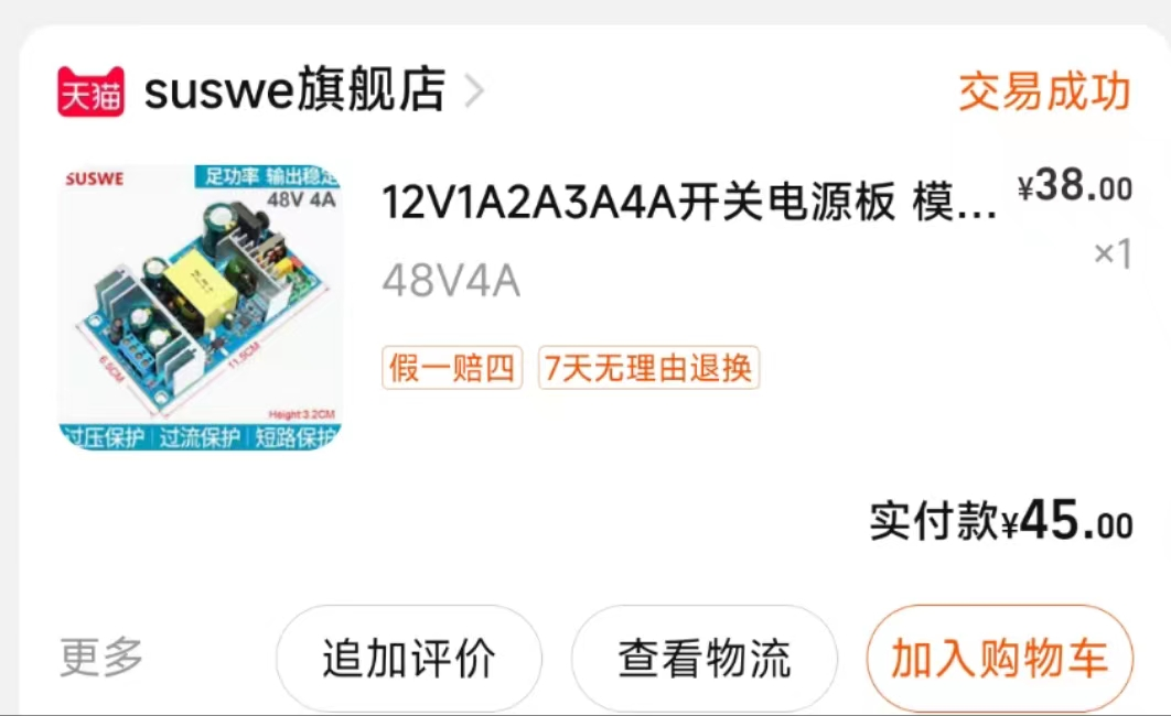
U14 is the auxiliary power module, available on Taobao.
1.4 Auxiliary Power Supply Circuit
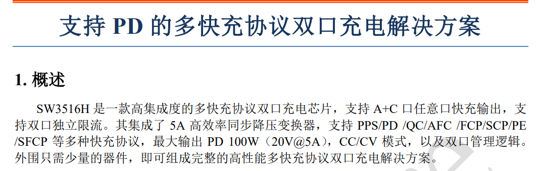
The auxiliary power supply consists of three Texas Instruments high-voltage input BUCK chips, an EG1163S step-down chip, and an SW3516H fast charging circuit. The SW3516H chip reduces the 23V voltage to the 5-20V fast charging voltage for mobile phones, supporting 100W fast charging.
The EG1163S is a synchronous step-down chip, and the MOSFETs are 100V 20A external MOSFETs in a DFN5x8 package .
The Texas Instruments LM5164 has very high performance, supporting up to 100V input, and so far, none have burned out, demonstrating its high reliability.

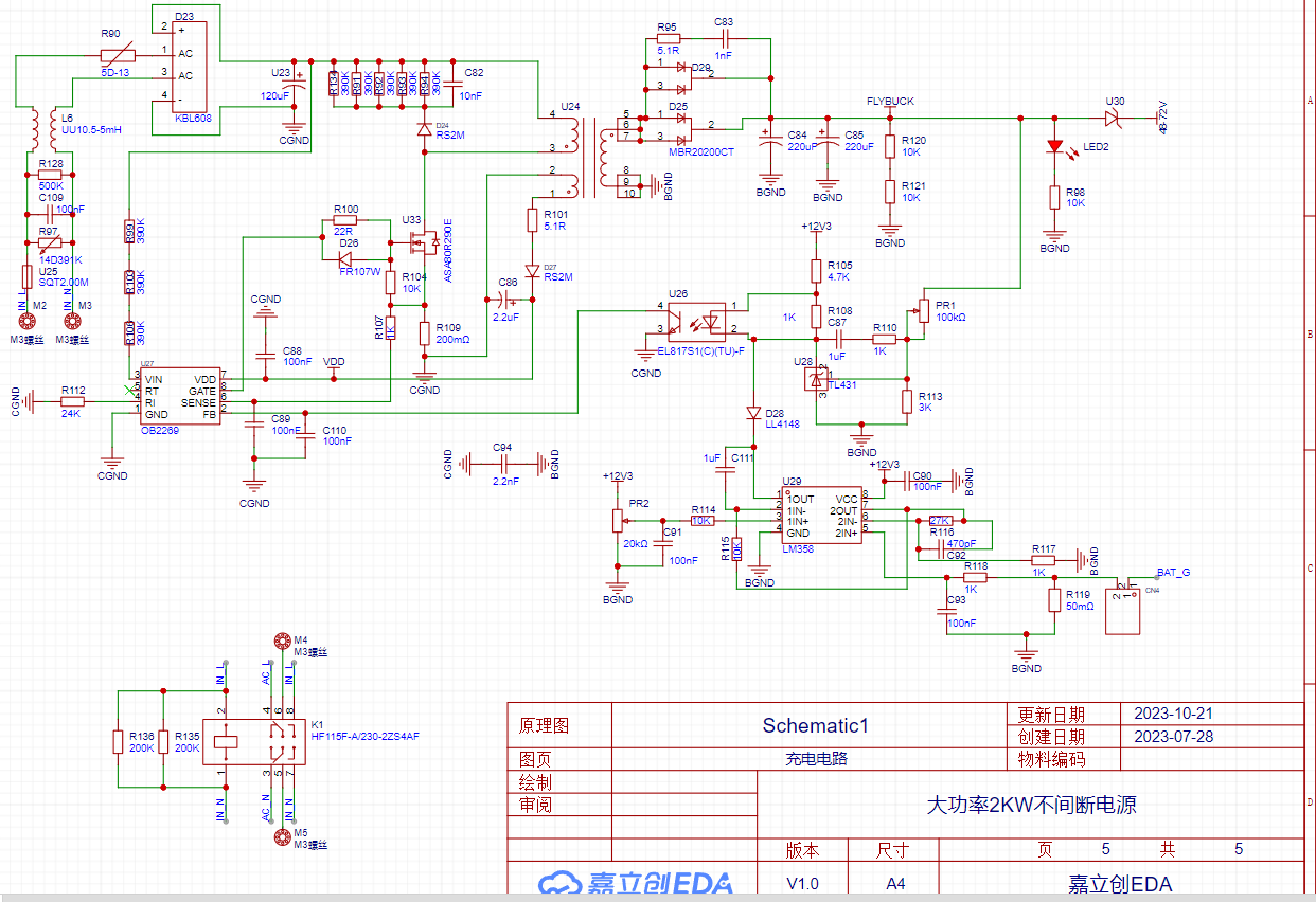
1.5 Charging Circuit
The charging circuit features AC input surge protection and capacitor current limiting protection. The main power management chip is an OB2269 flyback chip, and the power switching transistor is an 800V 10A or higher NMOS. The transformer was purchased from Taobao (you can buy it there). The output uses constant voltage protection and constant current charging.
An LM358 amplifies the current signal and then provides current feedback. During charging, the voltage decreases while the current remains constant. When the battery is fully charged, the current begins to decrease while the voltage remains constant. The relay is used for continuous switching.
Debugging Steps:
We should solder the flyback component first, as it is more difficult to adjust and is also the most dangerous. After soldering, adjust the voltage potentiometer to 48V, then connect a load, preferably a 40-ohm load. Rotate the current potentiometer clockwise, observing the ammeter to ensure a constant current. Then, switch to a 20-ohm load to check for a constant current effect. Finally, adjust the current to 2A.

For the LLC (Limited Cable) section, we can connect a current transformer in series with the rectifier bridge's preamplifier stage, apply a 200W load, adjust the frequency to 56kHz, and then observe whether the waveform is sinusoidal. If it is sinusoidal, then the LLC is in a resonant state. If the waveform becomes elliptical, it indicates inductive operation, meaning the frequency is too high.

Main Components BOM (Bill of Materials)
Model
Quantity
Purchase Channel
IRFP4568PBF
8
LCSC Mall
EG1163S
2
LCSC Mall
SGT50T65FD1PN
4
LCSC Mall
LM5164DDAR
3
(LCSC Mall)
, 47UH 30A inductor
(
Taobao),
modulation inductor
(
Taobao),
flyback transformer
(
Taobao),
EG8010 small board
(
Taobao) ,
SW3516H
(
Taobao) ,
LLC transformer
(
Taobao),
EG1611
(
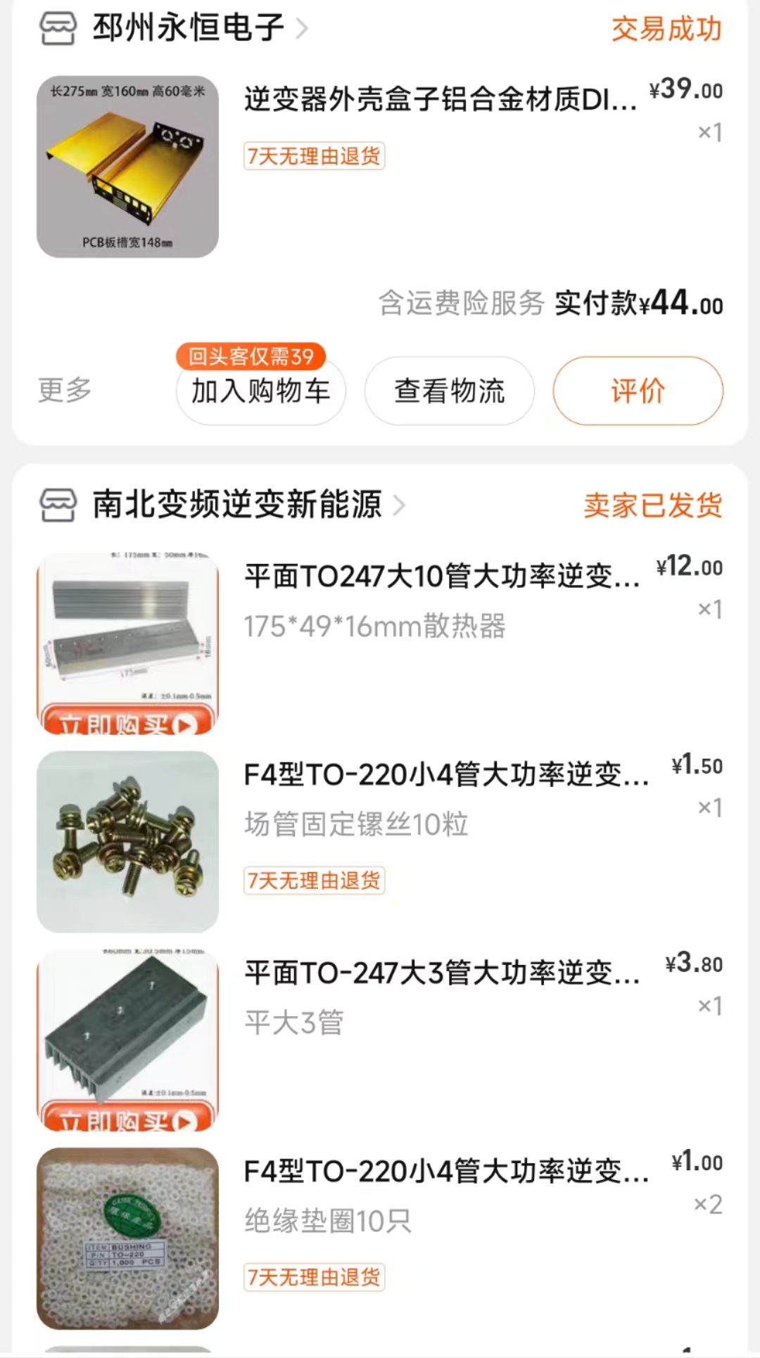
Taobao ),
casing
(
Taobao) .


Physical display
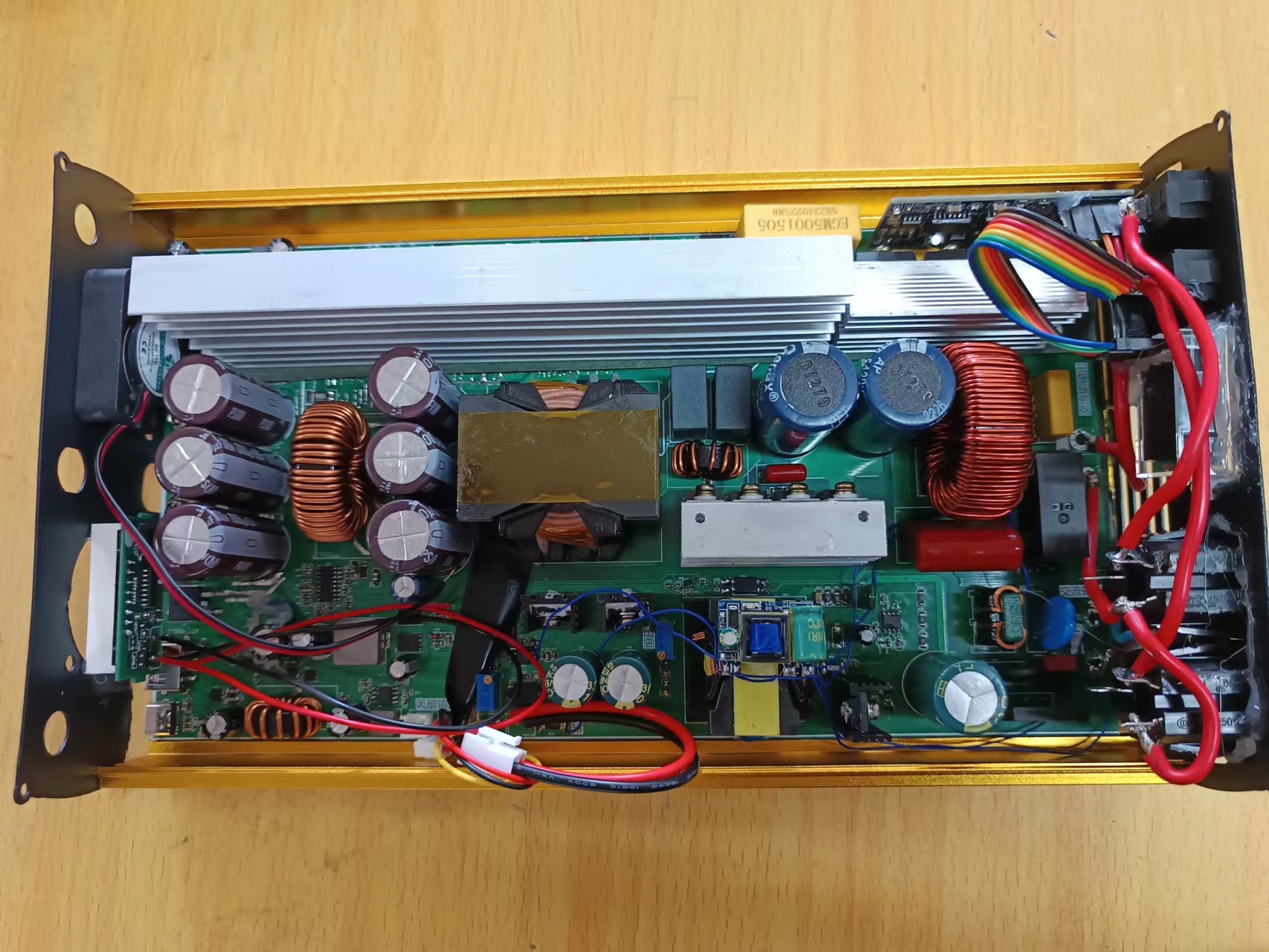
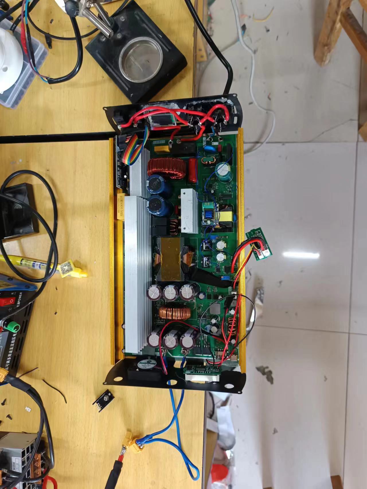
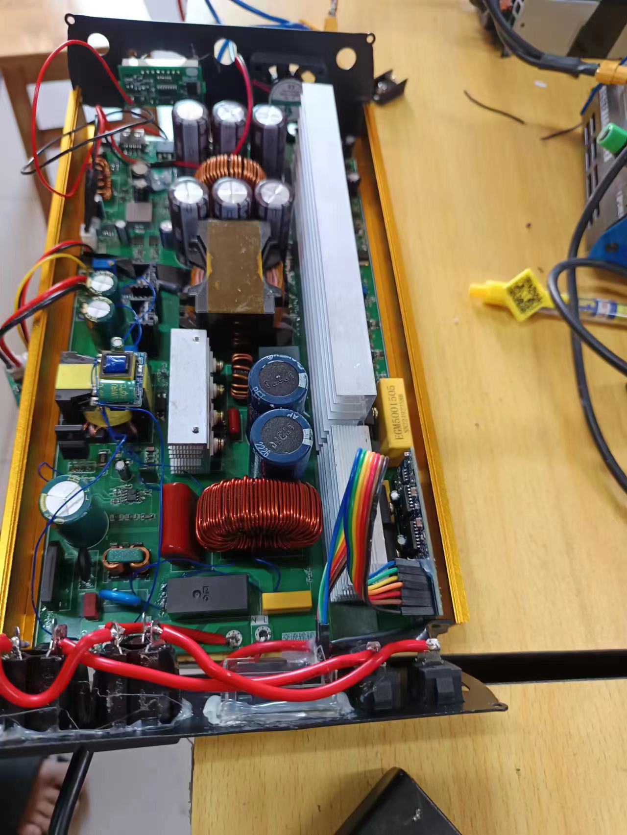

and design notes:
Remember to take proper insulation measures during installation, especially for the 220V output, as it can be harmful to the human body. Currently, the most difficult parts to debug are adjusting the frequency and setting the charging voltage and current.
Other parts are functional upon power-on. When connecting voltmeters and ammeters, pay attention to the positive and negative terminals; do not reverse them, as this can damage the meters.
Current testing shows stable operation. For heat dissipation, consider adding a cooling fan.
Other
Bilibili test videos
: https://www.bilibili.com/video/BV1Mh4y1i7vF/


 京公网安备 11010802033920号

 OR2T06A-5BA240


