(I) Design Background
A finger-clip pulse oximeter is a small device that uses spectral technology to calculate blood oxygen saturation by measuring the attenuation of different colors of light passing through a finger in the blood. This device does not require venipuncture; simply inserting a finger into the device yields results in approximately 10 to 30 seconds. Therefore, it is a convenient and safe method for monitoring blood oxygen saturation.
The principle of a pulse oximeter is based on the fact that when light of a certain wavelength passes through a human finger, oxyhemoglobin and deoxyhemoglobin in the blood absorb this light differently. The pulse oximeter emits light of a specific wavelength and then measures the degree to which this light is absorbed after passing through the blood, calculating the blood oxygen saturation.
Normal blood oxygen saturation should be between 94% and 100%. If blood oxygen remains below 90% for an extended period, it indicates severe hypoxia, requiring immediate medical attention. A pulse oximeter is a convenient and easy-to-use device, especially suitable for those who need to monitor their blood oxygen saturation for extended periods, such as people with certain chronic diseases. However, if blood oxygen levels remain below 80% for an extended period, medical attention should be sought immediately, as this may indicate a serious health problem.
(II) Hardware Design
To facilitate the development and testing of the finger-clip pulse oximeter, a core board based on the CW32L031C8T6 and an expansion board integrating various external modules were designed. The purpose of adopting an independent design for the main control and external circuits is to achieve support for multiple main control models and compatibility with multiple types of expansion boards, thereby facilitating learning and development for a wide range of enthusiasts.
1. Core Board
1.1 Design Concept
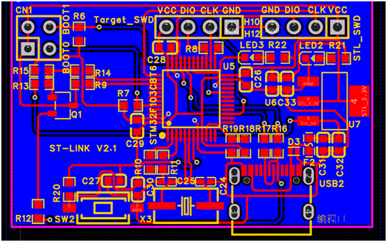
The core board consists of three parts: a power supply circuit, an MCU main control circuit, and a programmer circuit.
1.2 Power Supply Circuit The power
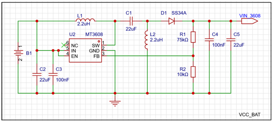
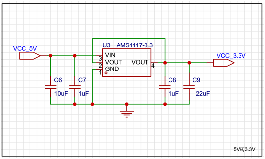
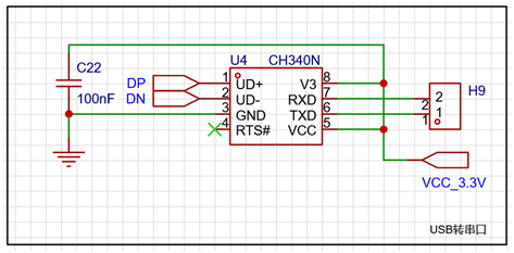
supply section provides two power supply methods: USB power and battery power, via a header. The USB interface uses a 16-pin, Type-C interface. While providing external power, it implements USB-to-serial communication functionality through a CH340 chip, and the serial port pins of the main control chip can be freely selected via the header. A CR1220 button battery is onboard, and a 5V output is provided through a SEPIC circuit composed of an MT3608 chip. The back end is connected to the AMS1117 chip to form an LDO circuit to provide 3.3V output.
(1) Schematic design
l USB interface circuit:

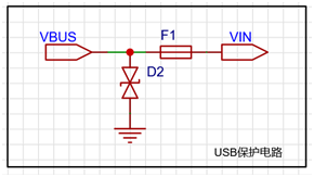
l USB overvoltage and overcurrent protection circuit:
l Power supply mode selection circuit:

l Battery powered Sepic boost 5V output circuit:
l 5V to 3.3V output LDO circuit:
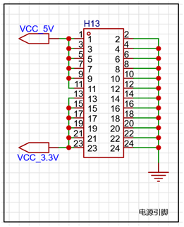
l Power output pin selection circuit: provides 6 5V, 6 3.3V and 12 GND pins
l Power indicator circuit:

l USB to serial port circuit:
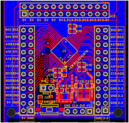
(2) PCB design

1.3 MCU circuit
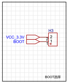
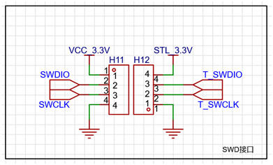
The MCU circuit uses CW32L031C8T6 as the main control chip. The 33 sets of IO interfaces, 2-pin Boot interface and 4-pin SWD programming interface are brought out through the pin header, and a reset button is provided.
(1) Schematic Design:
l MCU main control circuit:

l Filter circuit:

l Reset circuit:

l External crystal oscillator circuit:

l BOOT pin selection circuit:
l SWD programming interface circuit:
(2) PCB Design:
1.4 Programmer Circuit
The programmer circuit uses STM32F103CBT6 as the main control chip and implements the ST-LINK V2.1 programmer function. Since this part of the circuit does not belong to the core board function, please refer to the publicly available information on the Internet for the specific schematic diagram.
2. Expansion Board
2.1 Design Idea
The expansion board is mainly based on the development and design requirements of the pulse oximeter, and expands the relevant external equipment circuits, including the transmitting circuit, receiving circuit, button circuit, LED circuit, buzzer circuit, TFT display circuit, FLASH circuit, EEPROM circuit and core board interface circuit, etc., and supports the access of low power series core boards such as CW32L031 and CW32L083.
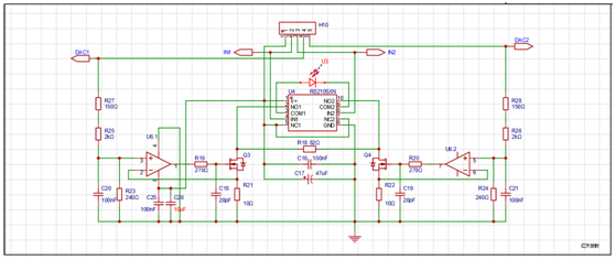
2.2 Transmitting Circuit
The transmitting circuit adopts the "RS2105+RS622" design scheme. A dual-channel switching circuit is constructed using RS2105 electronic switch chips to control the transmission timing; a constant current source circuit is formed by two operational amplifiers contained in RS622 chips and N-channel MOS transistors, and the current magnitude is controlled by PWM signals to achieve the purpose of controlling the strength of the transmission signal. A dual-wavelength transmitting tube of "660nm red light + 900nm infrared light" is used, which is internally connected in reverse parallel, and the transmission timing and transmission power are controlled by the above-mentioned H-bridge circuit.
(1) Schematic design
(2) PCB design

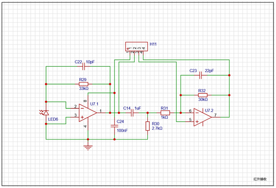
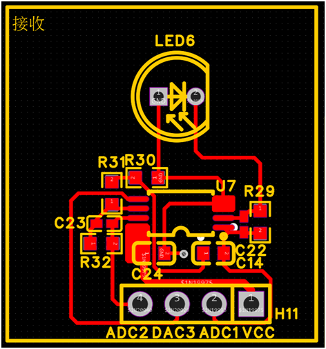
2.3 Receiver
circuit The receiver circuit uses RS622 dual-channel operational amplifier chips as the core. The front stage is connected with 200KΩ resistors and capacitors to form a transimpedance amplifier circuit to collect and amplify the "DC + AC" mixed signal; the rear stage is connected with negative feedback resistors to form a signal amplification circuit to amplify the AC signal; the front and rear stages are coupled by capacitors and form a high-pass filter with resistors to effectively filter out DC signals.
(1) Schematic Design
(2) PCB Design
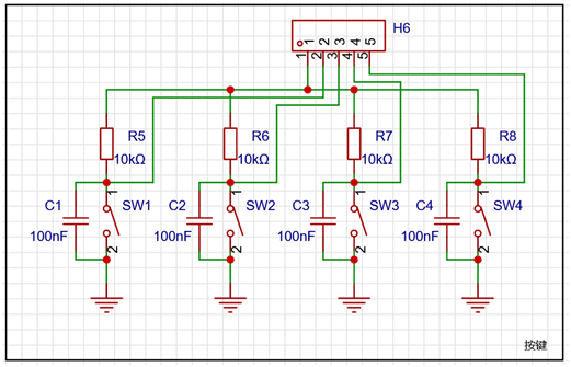
2.4 Button Circuit The button
circuit design has 4 independent buttons. Each button is connected to a hardware debouncing circuit through parallel capacitors. The buttons are connected to the four IO ports of the MCU through resistors. When the button is pressed, it is at a low level (low level is active).
(1) Schematic Design
(2) PCB Design

2.5 LED Circuit
The LED circuit design has 4 independent LEDs. The LEDs are connected to the four IO ports of the MCU through resistors. The design is to light up when the IO port outputs a high level (high level is active).
(1) Schematic Design

(2) PCB Design

2.6 Buzzer Circuit
The buzzer circuit uses a 2KHz passive buzzer as the core component and an N-channel MOS transistor as the switch. The buzzer is driven to sound by outputting a PWM signal of a certain frequency.
(1) Schematic Design

(2) PCB Design

2.7 TFT Display Circuit The
TFT display circuit is used to drive a 0.96-inch full-color LCD display. It also has an 8P drawer-type FPC interface and an 8P pin header interface, which can be used to connect a display with a soft flat cable interface and a display module with a pin header, respectively. Meanwhile, a PNP transistor is used as a switch, and the screen backlight is controlled by the PWM signal with a certain duty cycle output by the MCU.
(1) Schematic design

(2) PCB design

2.8 FLASH circuit
The FLASH circuit mainly designs a set of SPI interfaces to connect the W25Q128JVSIQ device.
(1) Schematic Design

(2) PCB Design

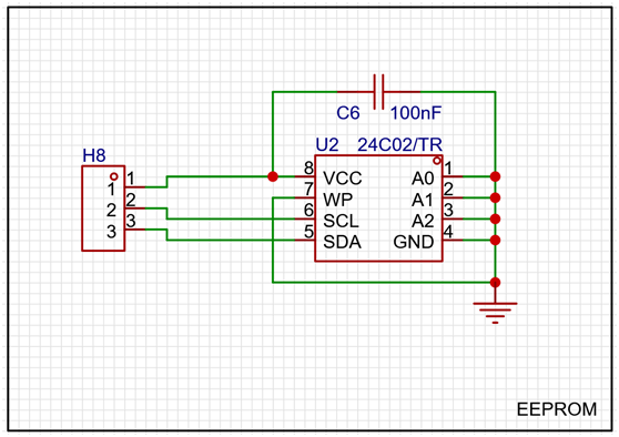
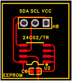
2.9 EEPROM Circuit The
EEPROM circuit mainly designs a set of IIC interfaces for connecting 24C02/TR devices.
(1) Schematic Design
(2) PCB Design
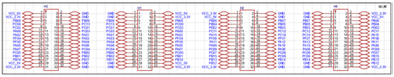
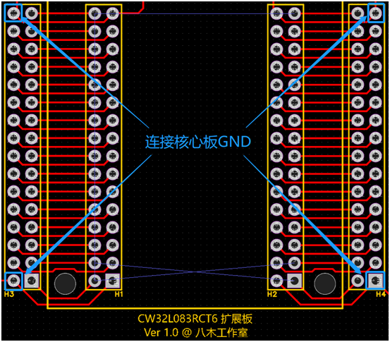
2.10 Core Board Interface Circuit The
core board interface circuit is mainly used to support the access of low-power series core boards such as CW32L031 and CW32L083. Since the number of pins of the above chips is different, the maximum number of pins is used as the design standard. Therefore, when inserting MCU core boards with fewer pins such as CW32L031, it is necessary to avoid the four groups of pins 1, 2, 31, and 32, and connect the GND pin of the above four groups of pins to the GND of the core board through DuPont wires to realize the GND connection of various external devices of the expansion board.
(1) Schematic Design
(2) PCB Design
(III) Physical Display
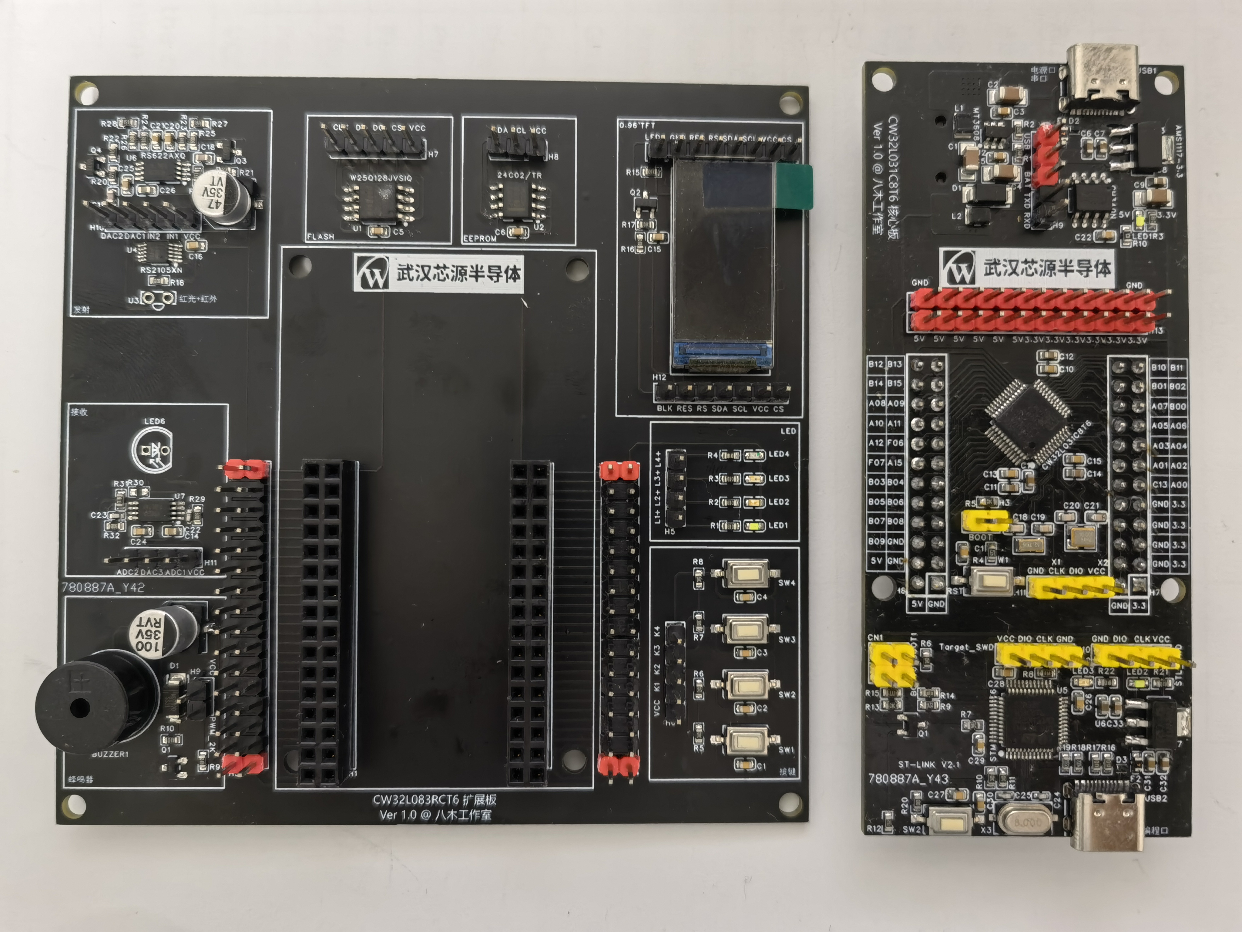
(1) Display of Expansion Board and Core Board Separately
(2) Display of Expansion Board and Core Board Combined

Real product video.mp4
PDF_Finger Clip Pulse Oximeter Development Kit.zip
Altium Finger Clip Pulse Oximeter Development Kit.zip
PADS Finger Clip Pulse Oximeter Development Kit.zip
BOM_Finger Clip Pulse Oximeter Development Kit.xlsx
91071
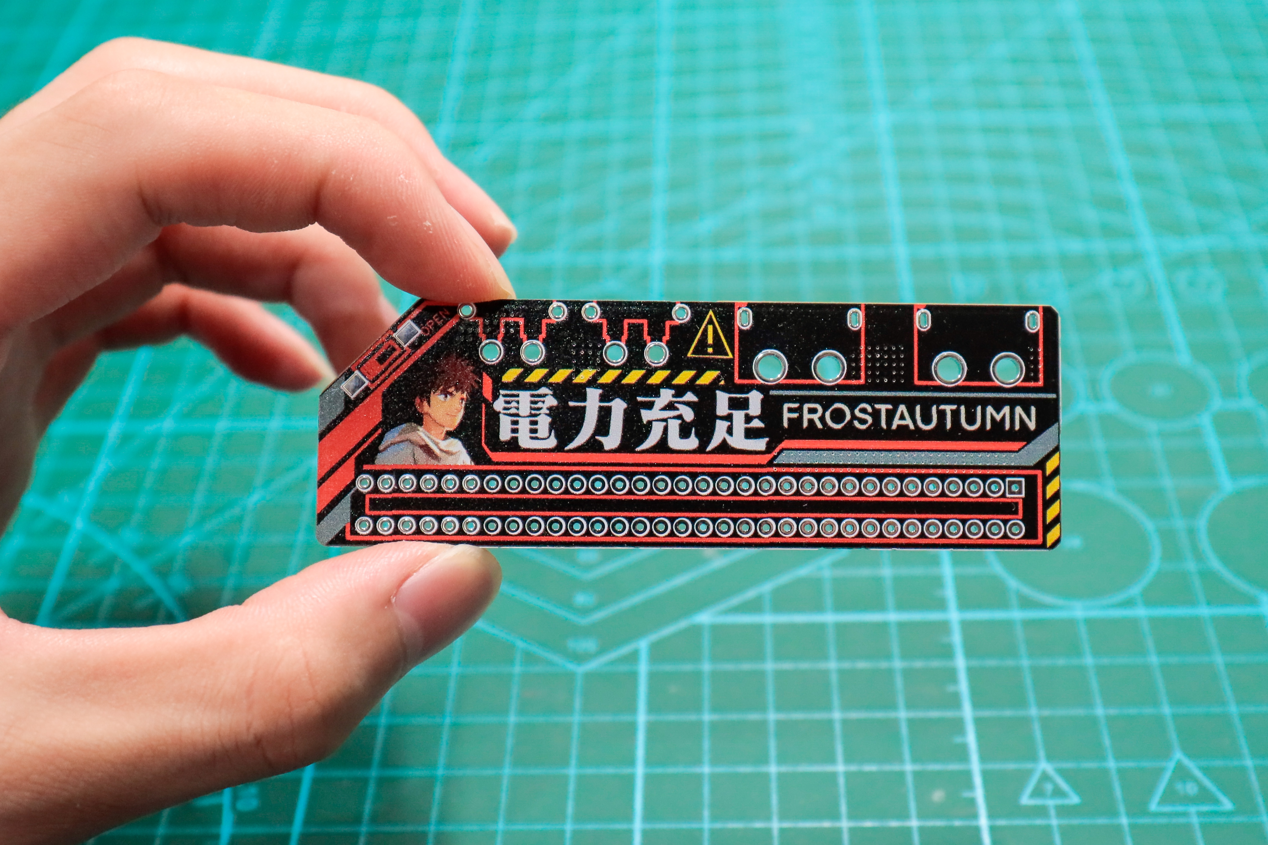
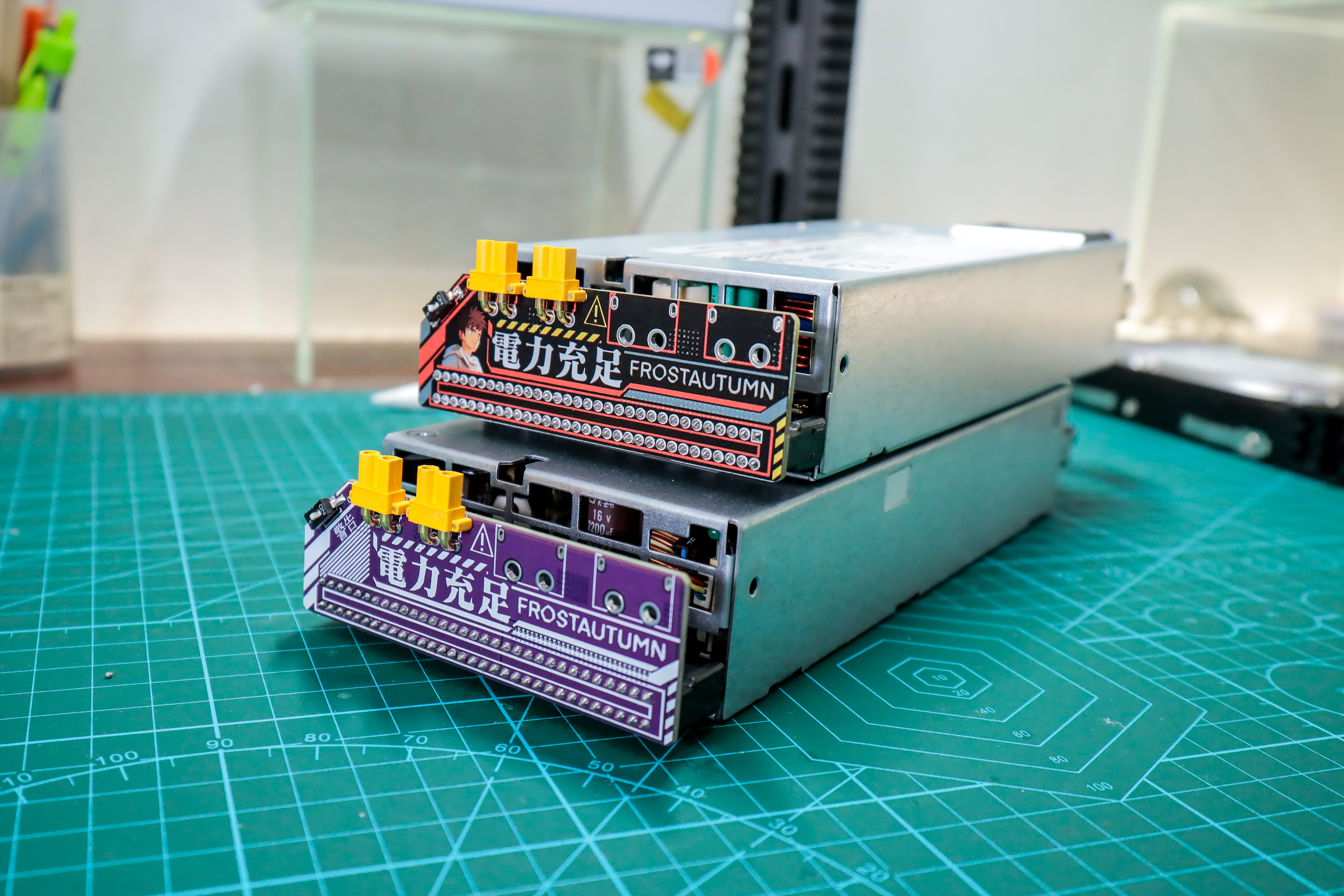
Huawei Server Power Adapter Board (Color Screen Printing)
A simple adapter board for Huawei 460W and 750W server power supplies.


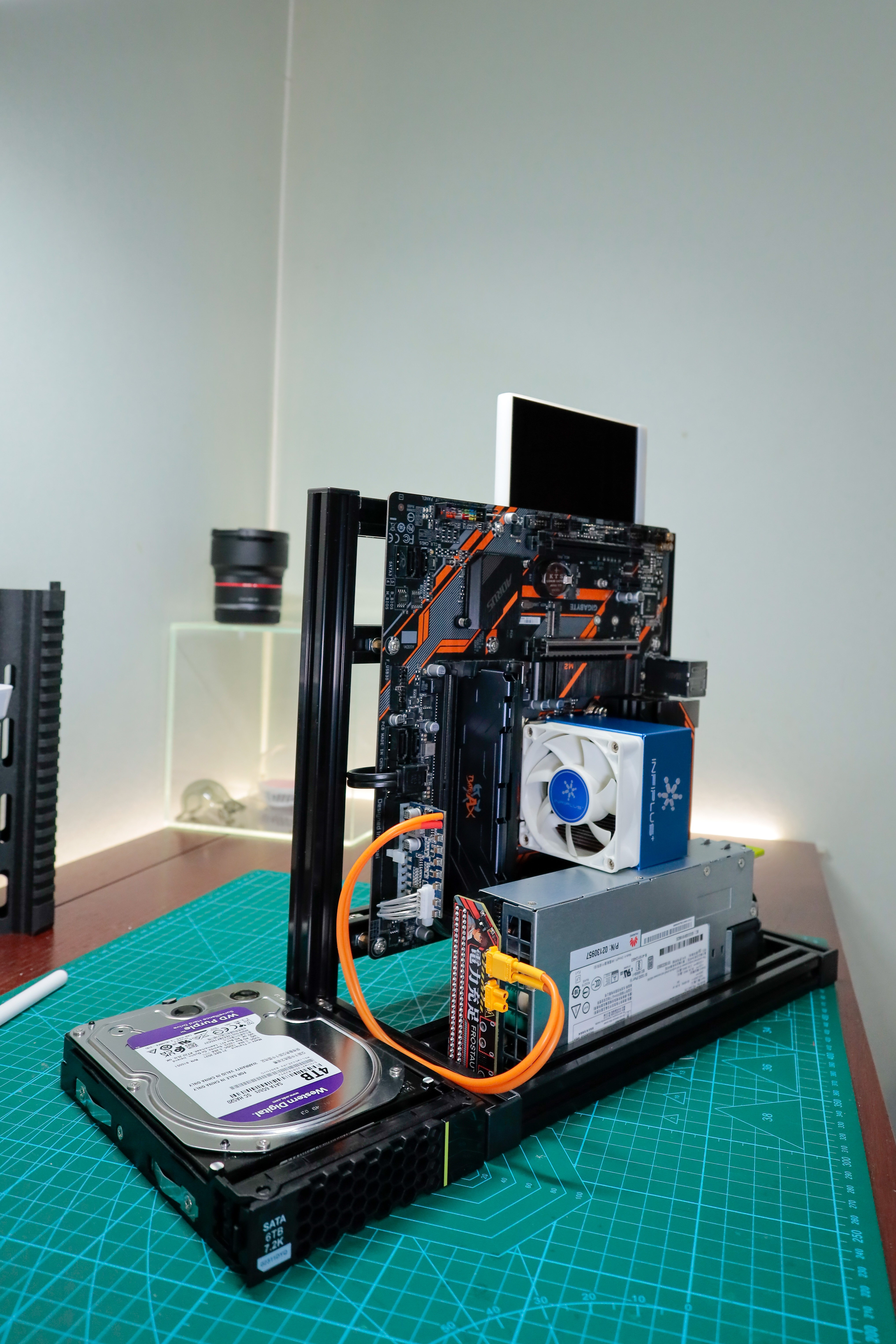
(For computer power supply)
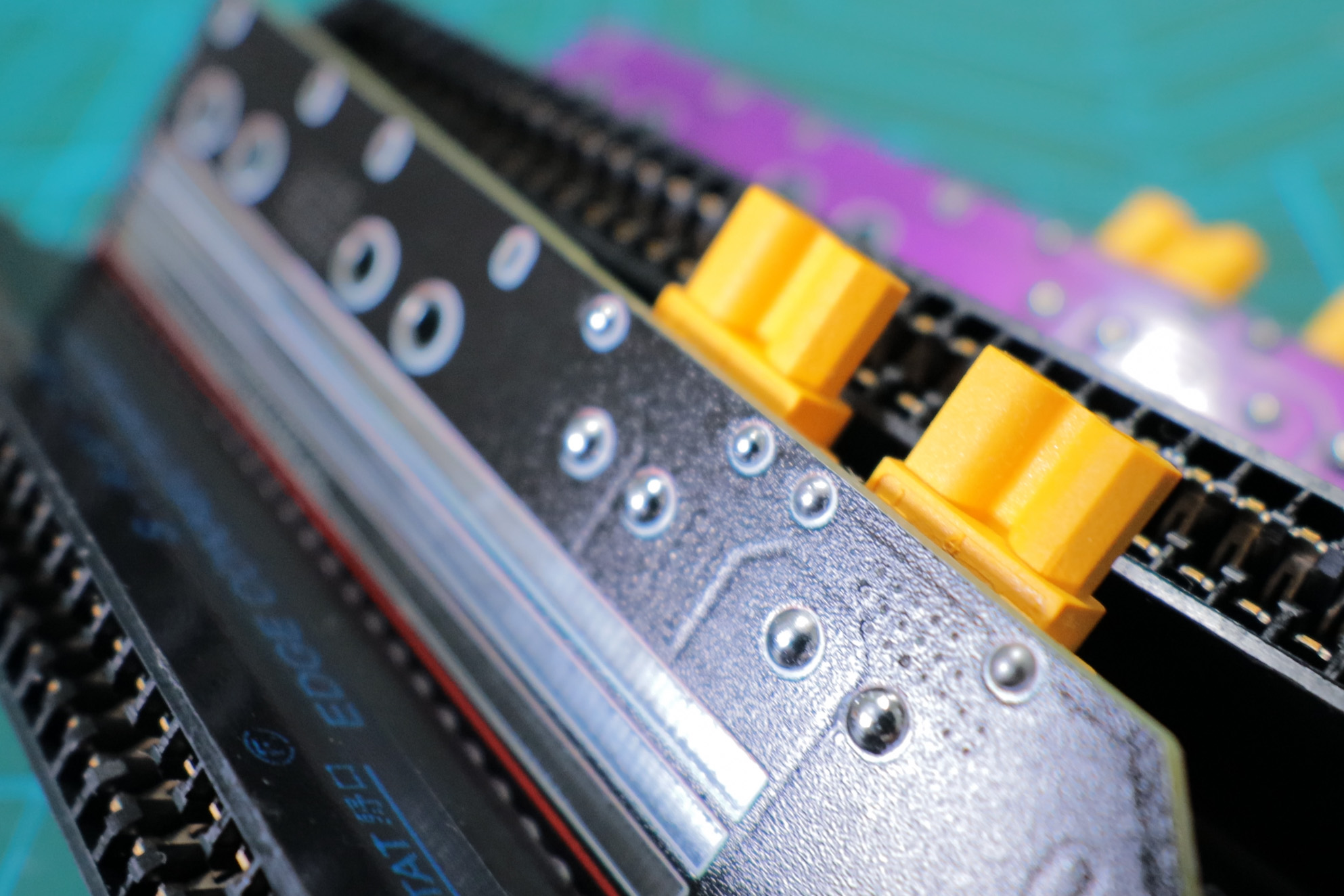
The input interface is a Noguchi 64P 2.54mm pitch connector,
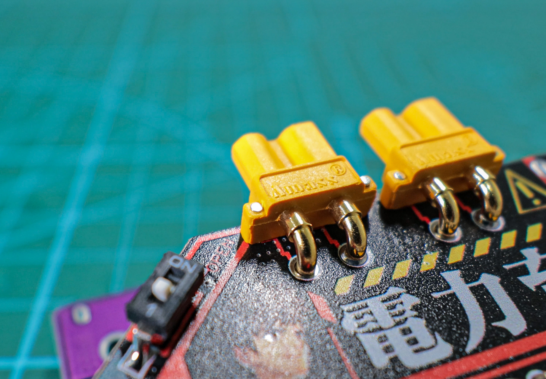
including two XT30 and two XT60 pins. Outputs
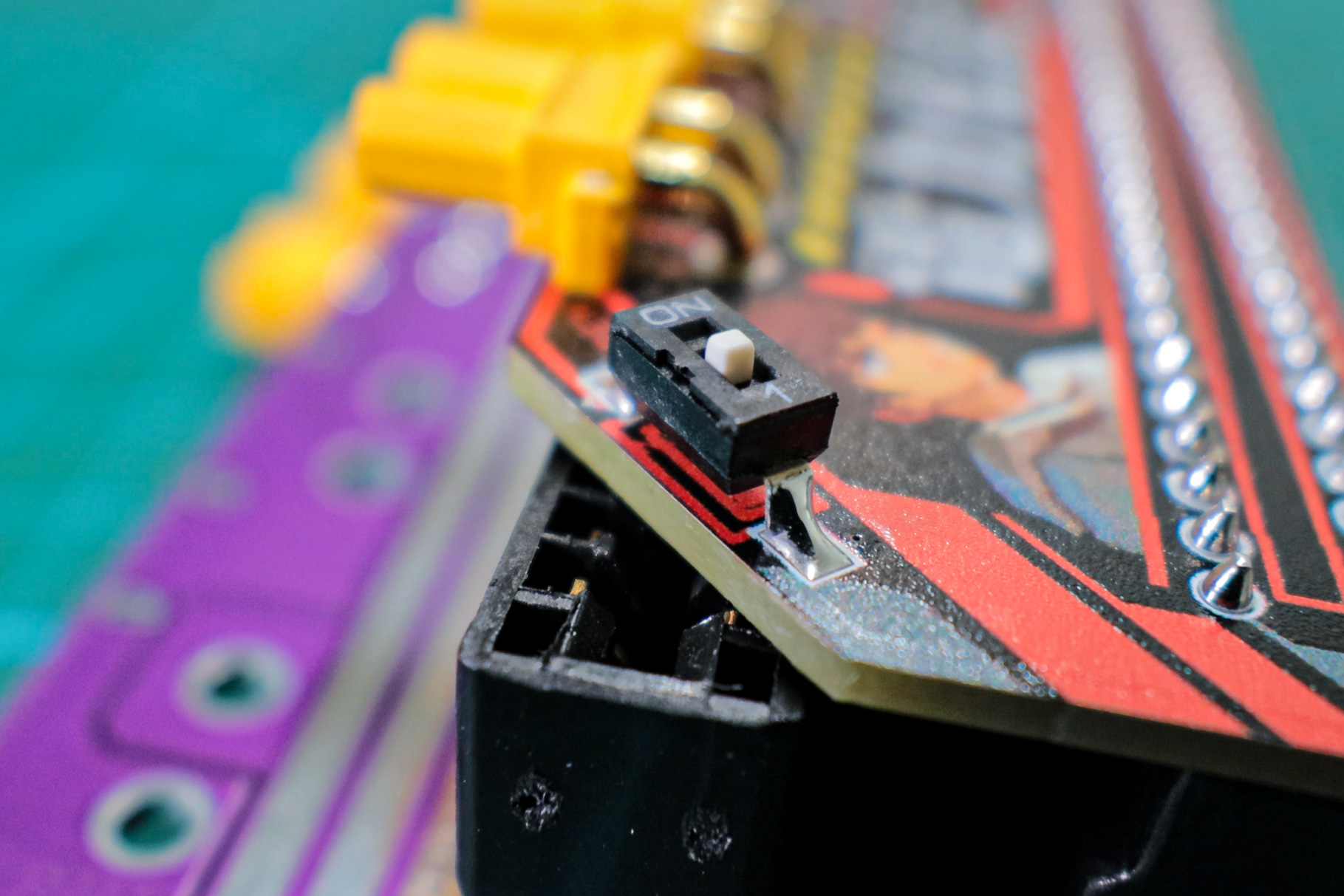
are controlled via a DIP switch to prevent accidental power-on
. The gold finger start pins must be pins 1 and 4.
If the project file is not displayed below, please click the option below it. ∀
PS: This product has been verified and is working correctly.
Gerber_4268032A_Huawei 460W Power Adapter Board_2022-10-03.zip
PDF_【Color Silkscreen】Huawei Server Power Adapter Board.zip
Altium_【Color Silkscreen】Huawei Server Power Adapter Board.zip
PADS_【Color Silkscreen】Huawei Server Power Adapter Board.zip
BOM_【Color Silkscreen Printing】Huawei Server Power Adapter Board.xlsx
91072
Earth Business Card
This is a fun and visually appealing card designed with the Earth theme and based on the Air001 chip. It includes peripherals such as an OLED screen, LED lights, buttons, and switches. It can display Earth information, set text, and support switching animations, as well as multiple lighting effects.
1. For a demonstration of the finished product, including
detailed instructions and functional effects, please see the following Bilibili video:
[Creative DIY] Make a cool "Earth ID card" for just fifteen yuan!
program file.zip
shell file.zip
PDF_Earth Business Card.zip
Altium_Earth Business Card.zip
PADS_Earth Business Card.zip
BOM_Earth Business Card.xlsx
91073
electronic


 京公网安备 11010802033920号

 VCS3_11


