This project describes
a Wi-Fi smart socket based on the ESP32-C3 microcontroller. The main controller chosen is the ESP32-C3-MINI-1-N4, the temperature and humidity sensor is the SHTC3, and the light sensor is the BH1750. The AC/DC power supply ultimately uses a pre-built module: HLK-5M05, and the DC/DC power chip is the SY8120B1ABC.
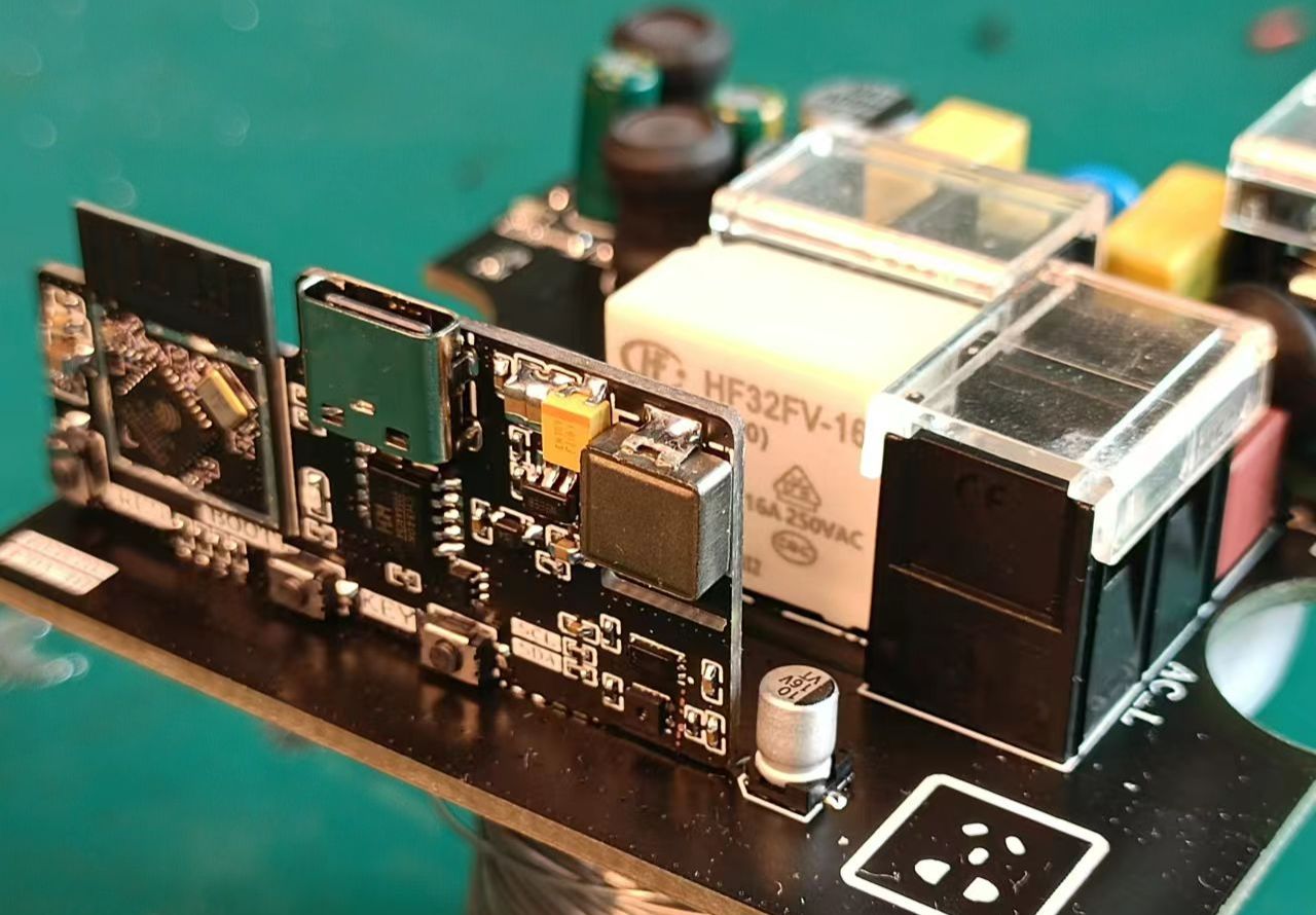
The project consists of two boards: one for the minimum system and sensors, and the other for high-voltage and energy metering. The boards are fixed together by soldering.
The assembled unit can be placed inside an 86-pin junction box, and the output is connected to the box's panel, creating a simple casing.
Software development is based on ESP-IDF v5.0, and the cloud platform used is Tencent Cloud, allowing interaction via the Tencent Lianlian mini-program.
Demo video: [Bilibili demo video] .
Hardware introduction:
Power supply
AC/DC
. Initially, the AC/DC circuit for this project was built using a custom chip, a non-isolated solution. However, during later debugging, the relay activation caused the power chip to overcurrent and restart, so a pre-built AC/DC module was used instead. Cost wasn't a primary consideration during the initial design, so the chosen module may not be the most cost-effective.
The HLK-5M05 module measures approximately 38 x 23 x 18 mm. While it fits in an 86-pin junction box, its size is somewhat large. At the time, the priority was functionality, so further consideration wasn't given to this.
The circuit, based on the HLK-5M05 datasheet, only required adding a fuse and a varistor at the input, followed by several filter capacitors and a power indicator at the output.
The DC-
DC converter handles the 5V to 3.3V conversion, powering the ESP32-C3 minimum system and sensors.
The circuit tested and found it feasible. Adding a 100uF tantalum capacitor at the output resulted in good ripple control.
An LDO wasn't chosen for this power supply because a DC-DC converter is more efficient, improving energy utilization.
For energy metering
, the HLW8032 chip was selected. This chip supports both isolated and non-isolated sampling, but since an isolated power supply was already in use, using non-isolated sampling would be strange. Therefore, isolated sampling was ultimately chosen for this project.
The transformer models are: current transformer ZMCT103C and voltage transformer ZMPT107-1.
Practical verification shows it's feasible, but software debugging requires knowing the voltage, current, and active power of the electrical load to calculate the isolation sampling coefficient.
The environmental sensor is an SHTC3
temperature and humidity sensor
, using the IIC protocol. Nothing much to say about this.
The optical station sensor is
a BH1750, also using the IIC protocol. The light sensor... well, it's not very useful at the moment, because if it's on the board and inside the housing, it can't measure ambient light.
I haven't thought of a better solution yet; not soldering this part of the circuit doesn't matter.
For the minimum system
, I tried a USB virtual serial port, but I didn't know how to use it, so I used a CH340, specifically the CH340K, in an ESSOP-10 package, which is relatively small.
Why not use a CP2102 for a small package?
Budget was limited, and the CP2102 is too expensive,
so in the end, a serial port with automatic download was used.
Software introduction:
Cloud platform
. Let me introduce how to operate the cloud platform.
To create a new product
, open the Tencent Cloud IoT Platform at https://console.cloud.tencent.com/iotexplorer and
click "Use Now" under "Public Instances" to access the instance overview. Then, create a new project, filling in the project name and other details as instructed.
After the project is created, click the project name to enter product development, where you can create new products. Click "Create New Product" in the upper right corner. For the
product name, enter your own name
; for the product category, select "Standard Category," then search for "Socket."
For the device type, select "Device
Communication Method," "Wi-Fi + BLE
Authentication Method," and "Key Authentication."
For the data protocol, select "Object Model
Description," which is optional.
You will then see the product you just created.
For product development,
click the product name you just created to enter the product development page. In
the "Object Model" section
, you need to define the product's physical model. You can directly import the attached "Wi-Fi Smart Socket Tencent Cloud Physical Model.json" file for a one-step process. After importing, you can quickly review it; if everything is correct, proceed to the next step. For
device development
, depending on your needs, I'm using SDK-based development, so I just click "Next." For
interaction development,
review each section and complete it according to the prompts.
In the smart linkage configuration, select ambient temperature, ambient humidity, light intensity, and active power as conditions, and the power switch as a task, for easy customization of scenarios later. For
device debugging , create a new device and enter a name. Then open the device interface to see the device information, including the product ID, device name, and device key. That's basically it; the next step is the software. Proceed with batch production as needed. The software code can be obtained from the GitHub repository: https://github.com/fairy618/Smart_Socket. Note that this project involves 220V and carries certain risks; please exercise caution when replicating. Update Log 2023/07/30 Initial Release


 京公网安备 11010802033920号

 HDI0811ARF8H3


