I. Introduction
This project originated from the STC forum: https://www.stcaimcu.com/forum.php?mod=viewthread&tid=5382&extra=page%3D1. It is
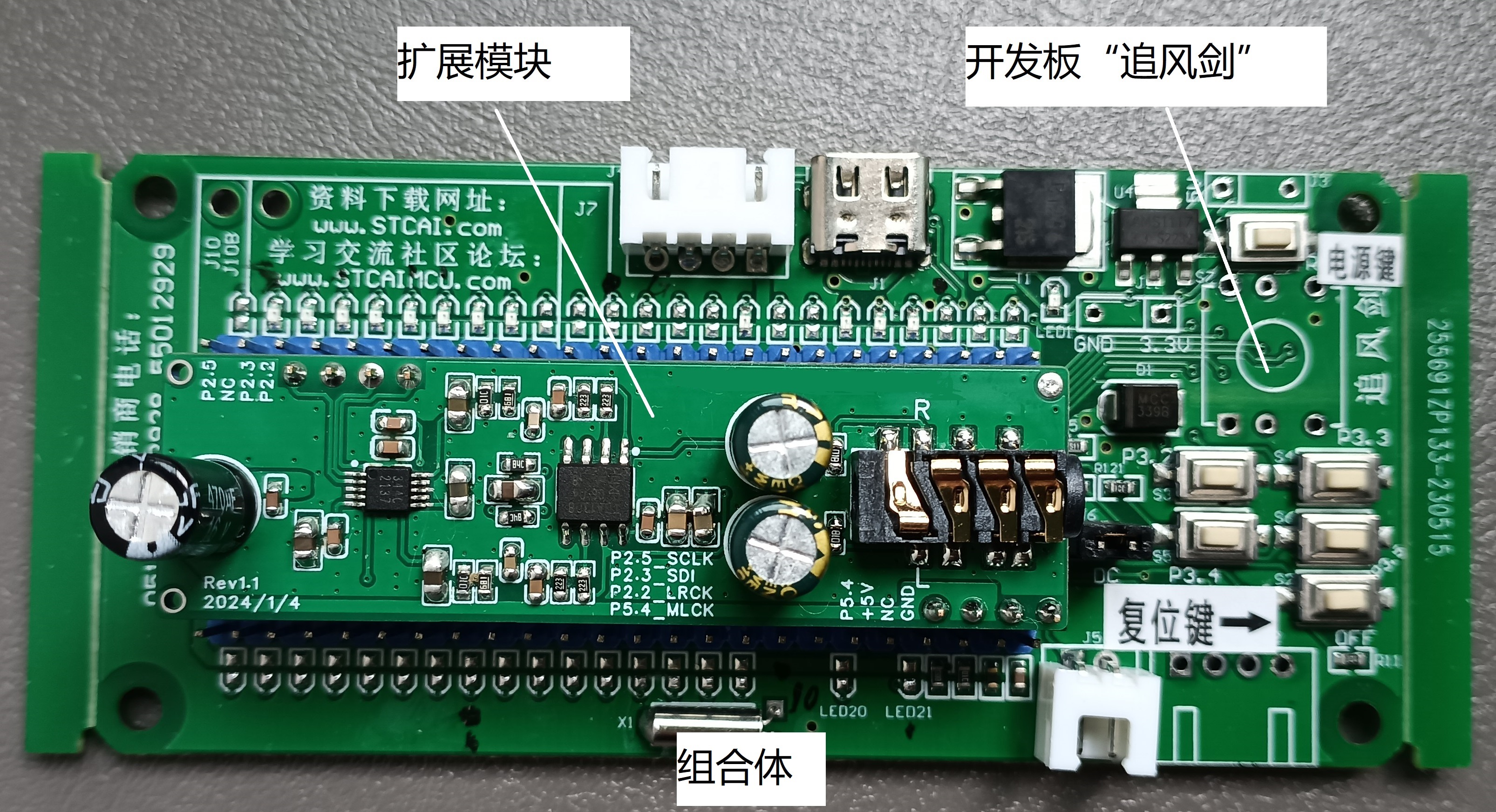
a test hardware developed by STC engineers based on the firmware of the STC32F series sound cards.
The STC32F series supports I2S, naturally leading to applications in the audio field.
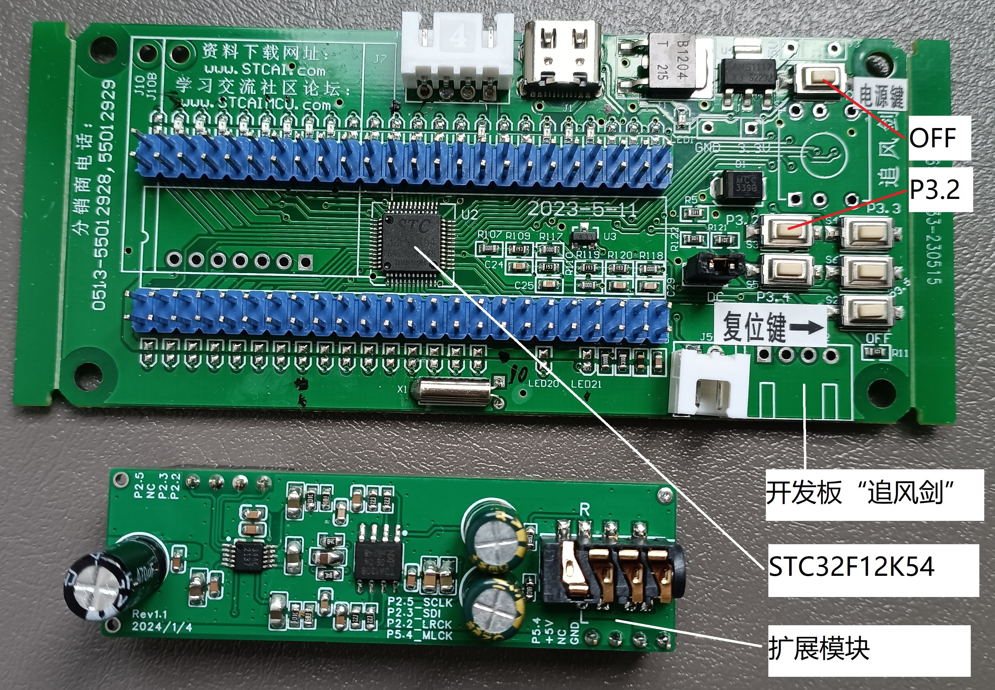
It is compatible with the "Wind Chaser" development board based on the STC32F12K54 and can be used directly after installation.
II. Applicable Headphones
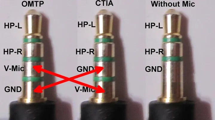
Since the microphone function is not used, the microphone pin of the headphone jack has been shorted to GND in this project, which can be widely used for the following types of 3.5mm headphones:
(1) 4-segment headphones: Chinese National Standard OMTP (National Standard) wiring sequence
(2) 4-segment headphones: International Standard CTIA (American Standard) wiring sequence
The impedance of the left and right channels to GND is low, ranging from tens to hundreds of ohms; The impedance of the microphone to GND is high, ranging from several thousand ohms; Therefore, it can be determined by measuring the DC impedance with a multimeter.
Taking the AM115 mobile phone headphones I have as an example, the actual measured impedance of the left and right channels to GND is 32Ω, and the actual measured impedance of the microphone to GND is about 2.1kΩ.
III. Soldering Recommendations:
The main issue is that the pins of the CS4344 are too dense, making manual soldering difficult. Other components are not difficult.
It is recommended to prioritize soldering the CS4344 before soldering other components.
For manual soldering, if you are like me and can't manage it, I suggest trying the following ultimate tricks:
(1) Soldering iron + desoldering wick + flux + board cleaner: First, solder the CS4344 to the PCB, build up solder on the pins, apply flux, solder the iron at 350℃, use desoldering wick to absorb excess solder, and finally clean with board cleaner;
(2) Soldering iron + heating plate + flux + board cleaner: Solder the PCB pads at 320℃, apply flux, place the CS4344 on it, use the heating plate to melt the solder, and finally clean with board cleaner. Do not over-solder the pads, as this can easily lead to solder bridging.
It is recommended to use a multimeter in continuity mode to check all adjacent pins of the CS4344 to eliminate solder bridging.
Among them, the power supply pins pin9 and pin8 are adjacent. The red probe of the multimeter should be placed on pin9 to avoid the risk of damaging the chip. I soldered one badly, which may be due to this reason; it may also be because I repeatedly heated the desoldering wire to remove the solder, and the high temperature caused the damage.
IV. Firmware
The aforementioned STC forum open source STC-USB sound card source code, 2023/12/8 Latest version: (1): 48K/16Bit/Dual Channel I2S Example (2): 48K/16Bit/Dual Channel I2S-DMA Example
Recommended DMA version has been uploaded to the attachment of this project; after testing, it can be used on both computer and mobile phone USB.
Firmware download development board: In addition to using the existing CH340 serial port download tool, the STC32 series has added direct USB download, which only requires a USB TYPE C cable, and does not even require additional driver installation, which is extremely convenient and fast.
V. Audio Quality:
Both the DAC chip and the amplifier chip affect sound quality. I think it's okay, and considering the price, it's a great deal.
I'm more concerned about background noise, which is most affected by PCB layout. I can tweak it a bit, but not much, and fortunately, it's almost inaudible in actual testing.
VI. Other:
Since there's no potentiometer, the volume is controlled solely by the computer/phone. In my tests, even at 10% computer volume, it was quite loud. Extra caution is needed. I recommend connecting the USB cable, adjusting the volume, plugging in the headphones, and then putting them on; otherwise, a sudden vibration can really hurt your ears.
VII. Photos
STC32F12K54-64MHz-LQFP48 to DIP48 Core Function Experiment Board - Chasing the Wind Sword - SCH-20230511.pdf
PDF_STC32 Wind Chaser Development Board—UAC Audio Sound Card—USB Sound Card Expansion Module.zip
Altium_STC32 Wind Chaser Development Board—UAC Audio Sound Card—USB Sound Card Expansion Module.zip
PADS_STC32 Wind Chaser Development Board—UAC Audio Sound Card—USB Sound Card Expansion Module.zip
BOM_STC32 Wind Chaser Development Board—UAC Audio Sound Card—USB Sound Card Expansion Module.xlsx
The Allwinner T113-S3 verification board features a TF card, NAND FLASH, RGB screen, OTG USB, HOST USB, RTL8723BS wireless network card, headphone and speaker functions.
Video Link:
Bilibili Video -- Function Demonstration and Introduction.
Welcome to watch my videos, 7 videos in total.
Project Introduction:
This project is a verification board based on Allwinner T113-S3, featuring TF card, NAND FLASH, RGB screen, USB OTG, HOST, headphone and speaker, and wireless network card (RTL8723BS).
Version Status:
2024.9.2 V0.2, not yet board-made, see the project update for specific updates.
2024.7.28 V0.1, board-made and verified.
Pinouts:
ADC, resistive touchscreen X1, X2, Y1, Y2;
E0, E1, E4-E13;
AVCC (1.8V), 3.3V, GND;
JTAG CLK, DO, DI, MS interfaces (no JTAG available, not tested);
Hardware Specifications:
PCB size 80x50 mm, easy to solder.
This project uses three MT3520 chips as the main power supply, providing 0.9V (core), 1.5V (memory), and 3.3V (peripherals) respectively.
The first LDO (1.8V) integrated into the T113-S3 power supply powers the RTC, PLL, LVDS, and DRAM 1.8V; a second LDO is not used.
The screen backlight is an MT9284-28J with PWM dimming.
Serial ports 0 (E2, E3) are brought out as debugging serial ports, using header pin connections, which can be easily switched to other serial ports for different firmware. The serial port chip is CH340N.
The external speaker uses an NS4158 chip, and the anti-distortion function can be enabled as needed.
Because there are many 0805 components available, the PCB is mainly based on 0805 components, with a small number of 0603 components.
TVS diodes are added to the USB and TF card interfaces (I'm not sure if this is correct; please correct me if I'm wrong).
Some circuits have been annotated with my own understanding; please correct me if I'm wrong.
Version 0.2's headphones and microphone use the Chinese standard 3.5mm plug, meaning from the outside in: left channel, right channel, microphone, and ground.
For the software,
I learned how to compile firmware from experienced developers on the Wacoo developer community and Allwinner forum; I'm a complete beginner.
Images show:
Figure 1: Panoramic view;
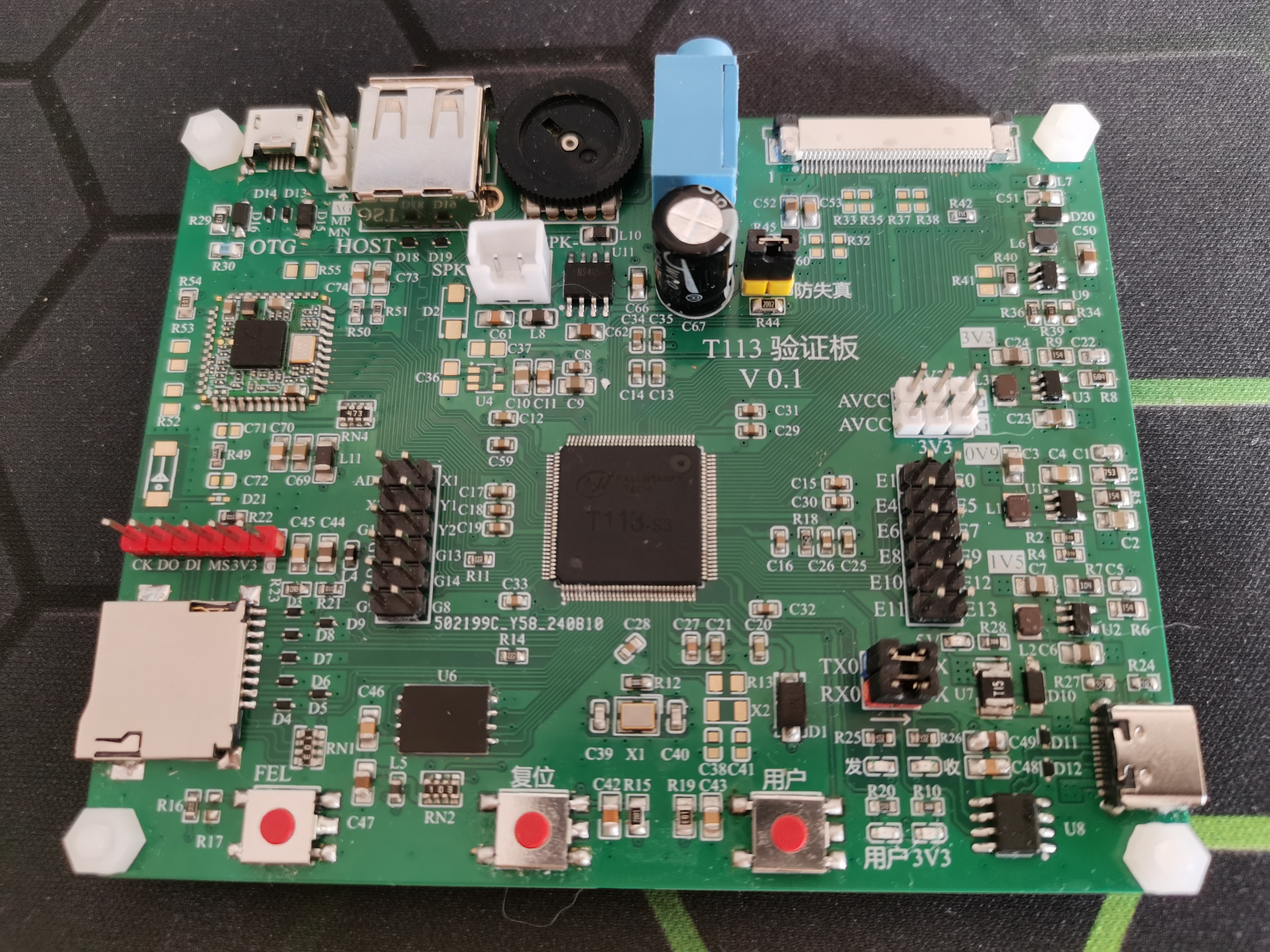
Figure 2:
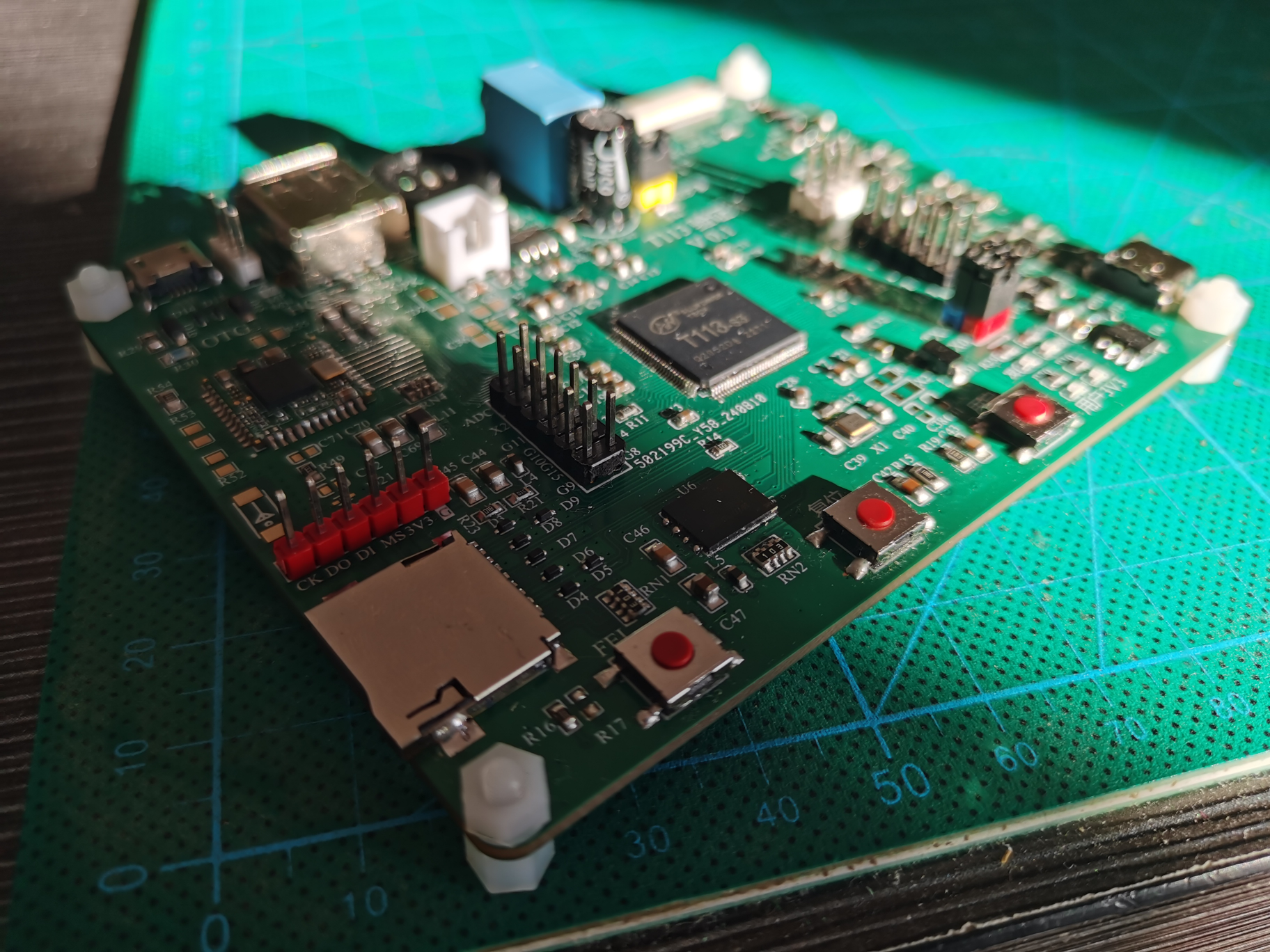
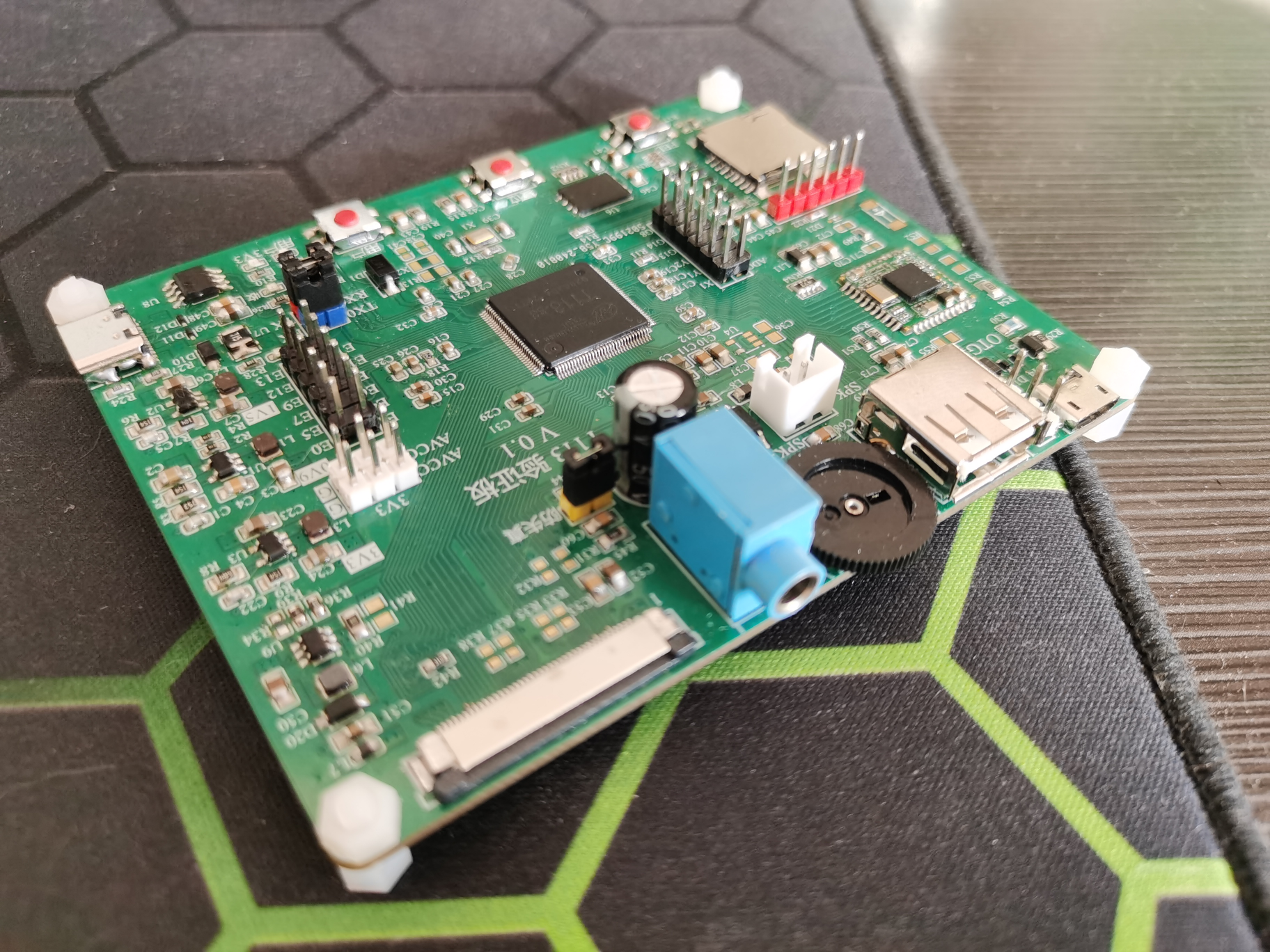
Side view; Figure 3: Interface.
PDF_Allwinner T113 Verification Board.zip
Altium_Allwinner T113 Verification Board.zip
PADS_Allwinner T113 Verification Board.zip
BOM_Allwinner T113 Verification Board.xlsx
91122
AG32VF407 DC Current Acquisition Instrument
Develop a wide-range DC current acquisition instrument for current sampling, using AG32 VF407 as the main controller with built-in FPGA, AD7606 for 200K synchronous sampling, and precision operational amplifier for signal amplification.
This project develops a wide-range DC current acquisition instrument for current sampling. It uses an AG32 VF407 as the main controller with a built-in FPGA, and an AD7606 for 200kHz synchronous sampling. A precision operational amplifier is used for signal amplification. For
the power supply section,
since it will be used with a USB interface connected to a computer, and the USB interface voltage is usually below 5V and fluctuates, affecting the precision operational amplifier, a boost-then-buck approach is adopted.
First, a DC-DC converter boosts the voltage to approximately 6.6V, then a TPS7A4701RGWR precision power supply is used to convert it to 5.0V. This power supply is specifically designed to power the precision operational amplifier and has very low noise. Currently, there are two hardware solutions for the
front-end
amplification. The analog front-end uses an INA186A5IDCKR and an RS8554 precision operational amplifier. Actual testing shows that the two solutions perform almost identically.
The RS8554 is configured as a differential amplifier, with a 2.5V reference signal superimposed on the non-inverting input. This ensures a 2.5V output when there is no current, a maximum output of 5V, and a minimum output of 0V.
Range
switching is achieved using a high-speed voltage comparator and FPGA, currently implemented via I/O interrupts in the software, with a switching time of 2.4µs. This speed is imperceptible to the load, as the load power supply typically has filter capacitors; µF-level capacitors are sufficient to support the 2.4µs switching time.
AD sampling
is performed using an AD7606, which simultaneously provides a 2.5V reference voltage to the op-amp. The system achieves sampling of positive and negative currents from 1µA to 10A with
resolutions below 1µA in the 400µA range, below 1mA in the 400mA range, and below 20mA in the 10A range . The main control unit uses an AGM32VF407VGT6 microcontroller with a built-in 2K FPGA. Furthermore, the positions of any digital I/O pins can be interchanged, greatly simplifying wiring. Currently, it's developed using a pure MCU; later, utilizing the on-chip FPGA for ADC sampling and level switching will result in extremely fast speeds. Enthusiasts are welcome to join group 691864140 to learn and exchange ideas together!
Ammeter firmware V1.hex
GPIO_VE file.txt
1252794055.mp4
PDF_AG32VF407 DC Current Acquisition Instrument.zip
Altium_AG32VF407 DC Current Acquisition Instrument.zip
PADS_AG32VF407 DC Current Acquisition Instrument.zip
91123
Rechargeable touch-sensitive color light painting radar sensor night light ambient light ornament with gravity sensor
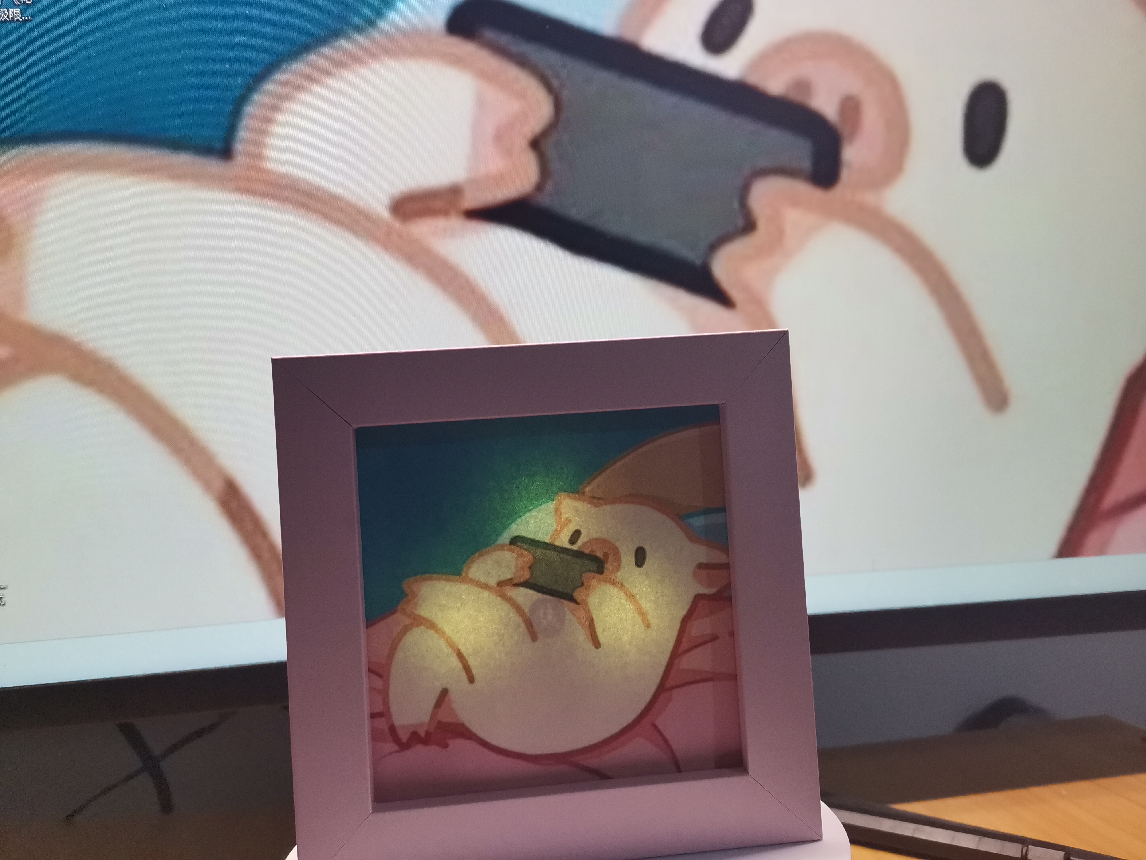
This rechargeable colored light painting features two touch buttons with spring-loaded controls and a cleverly interchangeable canvas. Various modes and parameters can be configured through combinations of short and long presses. It includes a radar sensing mode that saves data even when the device is powered off. Flipping the device turns it on and off. It can also be used as a desktop decoration or ambient light.
Rechargeable Touch Color Light Painting Radar Sensor Night Light Ambient Light Ornament with Gravity Sensor
Introduction:
This rechargeable color light painting features two touch buttons and a touch spring mechanism, allowing for easy replacement of the painting paper. Various modes and parameters can be configured through long and short press combinations. It includes a radar sensor mode that saves data even when the device is powered off. Flipping the device powers it on and off. It can be used as a desktop ornament/ambient light.
Open source: https://oshwhub.com/fly_yang/works [Hardware design data and burning files are stored in the main directory]

Parameters: Constant light battery life over 24 hours (can be used continuously with power after removing the battery), standby battery life over 100 hours, full charge time within 4 hours (5V-1A charging head)
Functions:
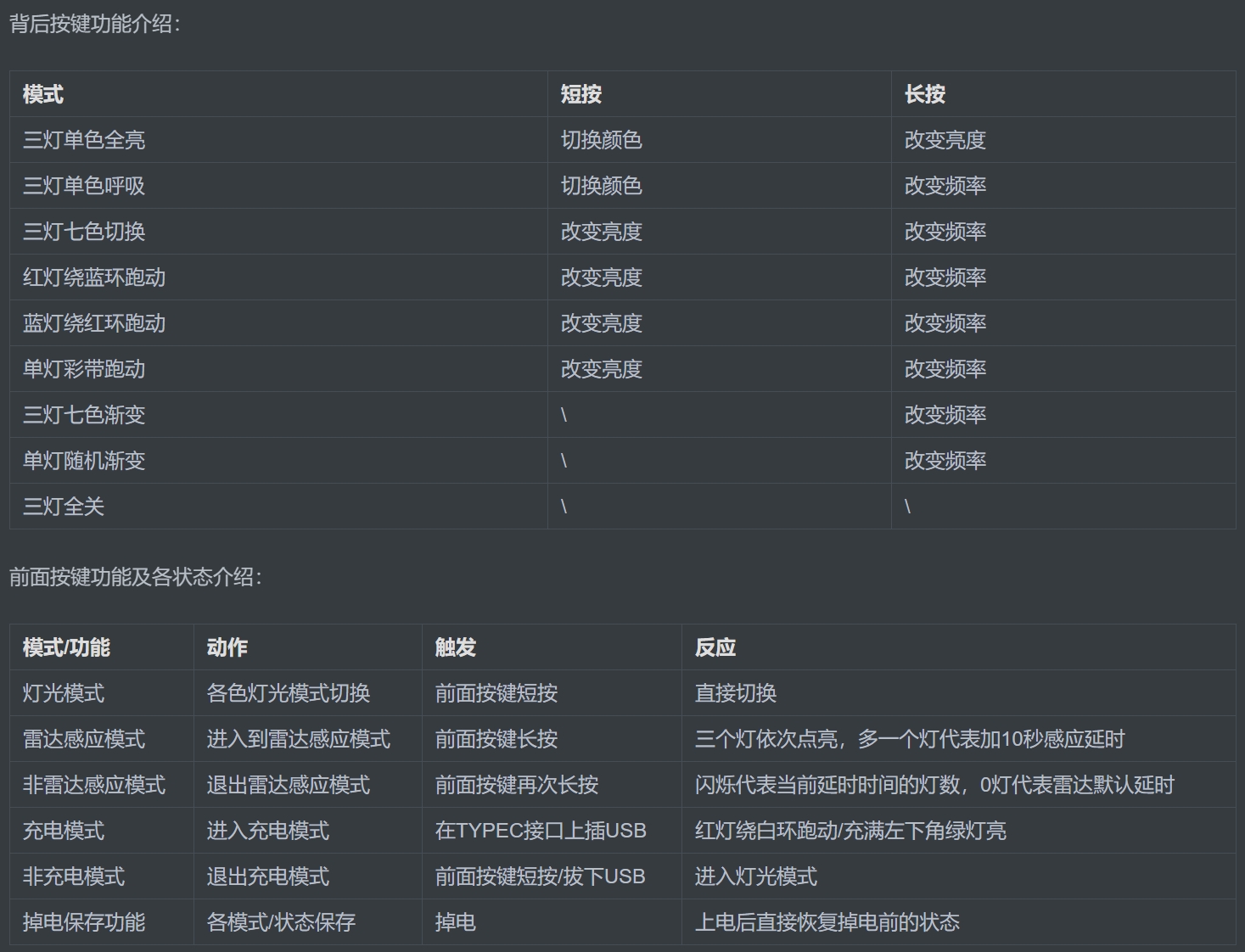
- Three lights in single color, three lights in single color breathing, three lights in seven colors switching, red light running around a blue ring, blue light running around a red ring, single light with a colored ribbon, three lights in seven colors gradient, single light with random gradient, and other lighting display modes;
- Short and long presses of the two buttons allow you to switch colors, brightness, flashing frequency, switch radar sensing modes, and configure radar sensing dead time.
It features USB charging with charging and full-charge indicators; the drawing paper can be easily changed (standard A4 paper is sufficient);
a tilt gravity switch; and data retention even when power is off.
Function introduction video: https://www.bilibili.com/video/BV14RYJeCEDY/
Application scenarios: In radar mode, it can be used as a motion-sensing night light; in constant light or other modes, it can be used as an ambient light; the drawing paper can be changed, serving as a reminder or commemorative item.
Main controller: CA51F551 microcontroller.
Hardware: TP4056 charging chip, LED green indicator light, WS2812 colored light, common resistors and capacitors, TYPE-C vertical female connector, XH2.54 horizontal battery socket, mercury gravity tilt switch.
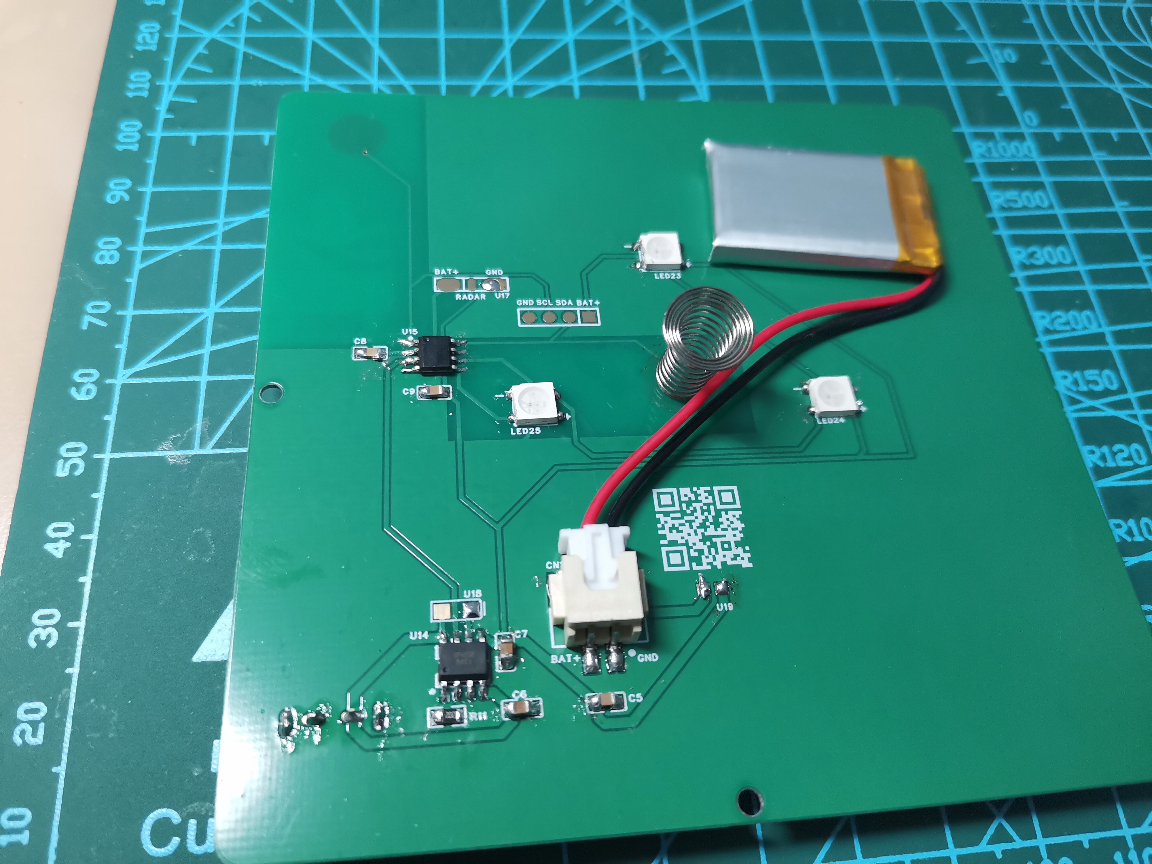
Assembly: 3.5-inch PS environmentally friendly square photo frame (with high-transparency acrylic glass), touch spring, 200mAh lithium battery, M2*8 screw
module. The LD1020 low-power microwave radar sensing module (maximum sensing distance 4 meters)
has the following parameters: These are self-tested and uncertified, for reference only, and do not constitute legal advice.
Function Description:
1. Front and rear touch button function description;
2. Assembly kit description:

You can purchase a photo frame to assemble it yourself. [Keywords: 3.5-inch square photo frame ornament]
Overview,

details, and usage information.

Vertical video carousel.mp4
Image landscape slideshow.mp4
Drawing paper materials.pdf
CA51F5 Series MCU User Manual_REV2.2.pdf
CA51F5 Series MCU Hardware Design Guide Rev 1.6.pdf
Light painting function demonstration.mp4
ca51fx.hex
PDF_Rechargeable Touchscreen Color Light Painting Radar Sensor Night Light Ambient Light Ornament with Gravity Sensor.zip
Altium Rechargeable Touchscreen Color Light Painting Radar Sensor Night Light Ambient Light Ornament with Gravity Sensor. zip
PADS Rechargeable Touch Color Light Picture Radar Sensor Night Light Ambient Light Ornament with Gravity Sensor. zip
BOM_Rechargeable Touch Color Light Painting Radar Sensor Night Light Ambient Light Ornament with Gravity Sensor.xlsx
91124
SimGETRO - An arcade-style game controller
A main control design scheme for an arcade-style game controller. Warning: You may not use or partially use the resources of this project for any form of commercial activity in any way or for any purpose! Discussion QQ group: 811740405
Warning: You may not use or partially use the resources of this project for any form of commercial activity in any way or for any purpose!
SimGETRO:
A main controller design for an arcade-style game controller. Please be gentle with your criticism, as this is a rough draft. Discussion QQ group: 811740405.
Main Controller - Core
Explanation:
Some design aspects were indeed not well thought out initially, but this project is difficult to modify... so let's just leave it as it is for now.
The specifications
utilize the WCH CH32V203 as the main controller, based on a RISC-V architecture. The CH422 acts as a co-processor for lighting .
It can connect to a 6-pin common-anode integrated microswitch, operating on 5V. It outputs
3 WS2812B signals
, 1 UART signal (3.3V, usable to drive PN532 card readers)
, 1 SPI signal (3.3V, usable to drive magneto-electric encoders)
, 2 high/low level inputs (onboard pull-up supports open-drain input, usable for GP1A173 signal input),
and 5 general button signals. It can also be programmable for other uses
and provides a debugging interface. Firmware
and compilation are supported using 5V power.
[Main controller source code repository]<
Please note that the source code may be updated at any time, and its availability and completeness are not guaranteed. The source code repository does not utilize the full capabilities of the chip. We welcome your contributions to the source code for collaborative development.
You need to obtain the firmware by compiling the source code. To compile the source code, please install EIDE in your VSCode as the development and compilation environment, and use EIDE to install RISCV_GCC and OPENOCD_WCH 8.2.0. If you are using a different version of OpenOCD, please modify your toolchain path in the build configuration -> right-click menu of your EIDE project. Please note that changing the toolchain version may cause compilation failure.
To flash the firmware, please use WCHISPTools and flash it via USB.
Card Reader - CardReader
Notes
2024-10-13 Updated the card reader PCB circuit design. The new design has better compatibility and can read irregularly shaped cards.
The specifications
use the PN532 as the card reader IC and the WS2812 as the LED
UART input. An IRQ signal was not specified.
The PN532 uses a 3.3V power supply, and the WS2812 uses a 5V power
supply. The PN532 uses a 4-pin XH2.54 input for power and UART signals, and the WS2812 uses a
3-pin PH2.0 input for power and LED signals . Please use a reverse XH2.54 4-pin cable and a reverse PH2.0 3-pin cable to connect the card reader and the main controller. The main controller repository currently does not contain the actual card reader implementation, only CDC pass-through PC test code for hardware testing. We hope someone can contribute code to help develop and improve this part. Additionally, the antenna impedance matching was done with a calculator, so we cannot guarantee that the impedance matching will match the actual frequency. It only works well so far, and we hope an expert can guide us on better impedance matching configurations. The front I/O panel (FrontPannel ) provides USB-B and 3.5mm audio inputs and includes ESD protection. Specifications: USB-B to XH2.54 4P with ESD ; 3.5mm audio to PH2.0 3P rear I/O panel - BackPannel : 3.5mm audio output ; PH2.0 3P to 3.5mm audio side button - Side: Provides side button backlight and optocoupler signal conversion ; One 2811 signal input, 5V, PH2.0 3P; One optocoupler signal extension, PH2.0 3P ; Integrated micro switch - Switch: Provides micro switch signal and simultaneously accepts LED signal for illumination; PH2.0 6P interface, providing one switch signal and one 5V common anode RGB signal input.
PDF_SimGETRO - An arcade-style game controller.zip
Altium_SimGETRO - An arcade-style game controller. (zip file)
PADS_SimGETRO - An arcade-style game controller. (zip file)
BOM_SimGETRO - An arcade-style game controller.xlsx
91125
RDA5807FP Ultra-miniature radio
An ultra-miniature radio, based on the RDA5807FP, measuring only 2.1cm × 2.4cm.
This radio chip uses the RDA5807FP,
requiring no programming and measuring
only 2.1cm x 2.4cm.
It is powered by a CR2032 button battery
, making it small and portable.
Originally, this chip required two volume control buttons
, but to reduce size, two 0603 packages
(controlled by shorting with a metal object) have
been added. Switches separate the entire circuit to prevent chip leakage and increase standby time.
Please feel free to ask any questions.
(Bilibili video link)
Sequence 01_1.mp4
PDF_Miniature Radio RDA5807FP.zip
Altium_Miniature Radio RDA5807FP.zip
PADS_Miniature Radio RDA5807FP.zip
BOM_Ultra-miniature radio RDA5807FP.xlsx
91126
E-paper STM32 NFC
NFC version of e-ink screen
Project Description:
NFC!
This project uses NFC to transmit data and power to the MCU and e-ink display.
Currently, the host computer only works on the Android version of the WeChat mini-program; the iOS version doesn't support NFC.
The idea originates from Zhihui's L-card, but the NFC label has been removed. The key point is that it eliminates the need for a battery!
Project-related functions:
After the host computer generates an image, it transmits the data to the e-ink display for refresh.
(No battery required.)
petal_20240603_151952.mp4
STM32G030F_266H850 high-resolution screen.hex
stm32G070_290Z94.hex
stm32G030F_290Z94.hex
stm32G030F_420Z99.hex
stm32G070_420Z99.hex
stm32G070_154C1.hex
stm32G030F_154C1.hex
epd154.3mf
epd266h high-resolution screen.3mf
epd420.3mf
epd290.3mf
stm32G0B1_420Z99_20240818.hex
STM32G070_266H850 High-Resolution Screen 20240621.hex
PDF_epaper stm32 nfc.zip
Altium_epaper_stm32_nfc.zip
PADS_epaper stm32 nfc.zip
BOM_epaper stm32 nfc.xlsx
91127
electronic


 京公网安备 11010802033920号

 L1384YD


