Current Version 1.3V:
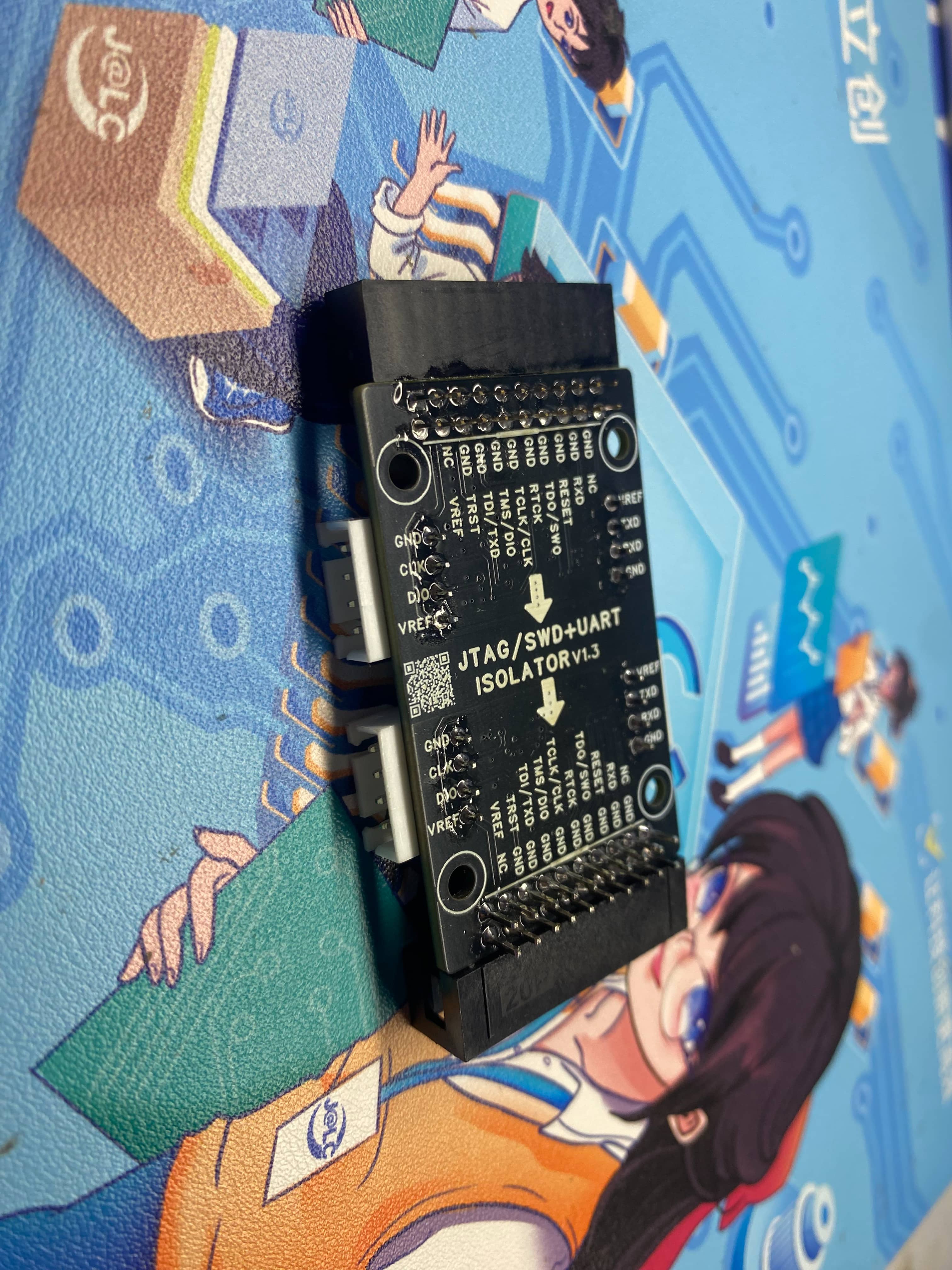
1. Added interface silkscreen on both sides for clearer indication
. 2. Increased isolation spacing.
3. Modified LED indicator positions.
Current Version 1.2V:
1. Replaced isolation chip for compatibility with other models and reduced cost.
2. Fixed SWD recognition issue (only recognized at low speeds).
3. Replaced analog switch chip.
Current Version 1.1V
: 1. Removed current limiting chip.
2. Modified SWD circuit.
Current Version 1.0V
: 1. Modified RX and TX order
. 2. Added serial port transceiver indicator.
Project Introduction:
1. This open-source isolation expansion board is compatible with the JTAG interface. It supports electrical isolation of serial port, SWD, and JTAG interfaces, suitable for motor debugging, BMS development, and other scenarios requiring isolation, enabling microcontroller program download or serial port testing.
2. For ease of use, we have brought out the SWD and serial port to an independent XH2.54 4P interface, which is compatible with the pin order of Zhengdian Atom. During download, this connector can be used directly, which is very convenient. It also supports female DuPont wire connection.
Features:
Plugs into the JLink's JTAG interface, has an onboard isolated power supply with a power indicator light. The programmer automatically outputs 3.3V after power-on.
Regardless of whether the isolated front end outputs 5V or 3.3V, the isolated power supply is uniformly 3.3V.
When there is data on the serial port, the Rx or TX light will indicate this.
If the programmer is hardware reset, the onboard RST light will also indicate this.
Instructions:
J-Link full suite driver file download address: https://www.segger.com/downloads/jlink/
1. J-Link supports simulated serial ports. The following command can be used to open it. This expansion card also supports direct serial port debugging from the J-Link debugger.
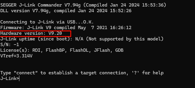
Taking J-Link-V9 as an example:
Open the J-Link Commander software,

ensure your version is V9 or higher,
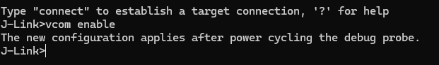
and enable the virtual serial port using the code
`vcom enable`.
After entering, you will see a prompt: "Restart for effect."
After restarting J-Link, you can use the virtual serial port. You can check the COM port number in My Computer - Device Manager.
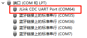
This enables data transmission and reception.
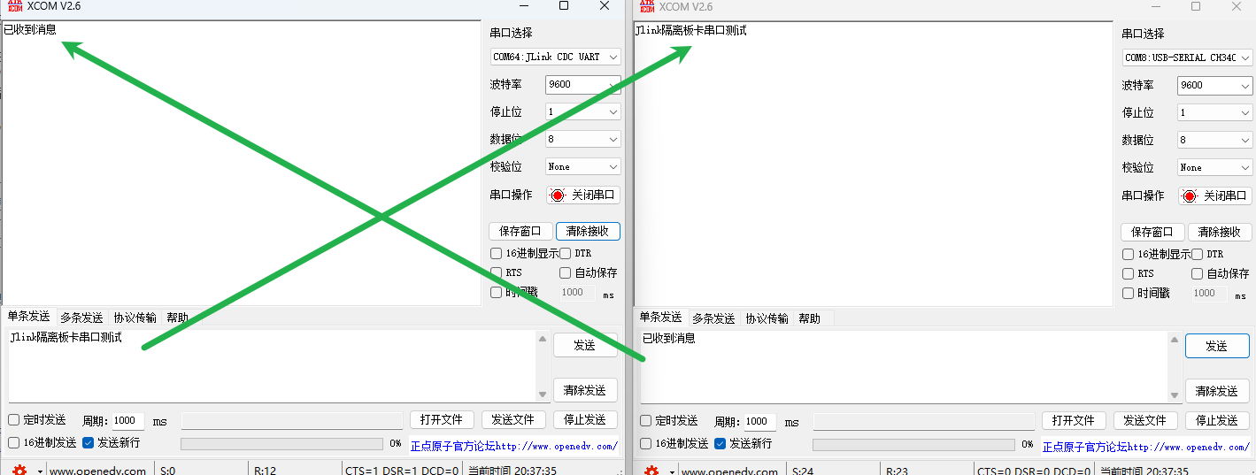
Due to my J-Link version issue, enabling high baud rates can easily cause serial port loss. My highest test baud rate was 25600. You can modify it according to your needs.
Other J-Link code:
Enable VCOM: vcom enable
Disable VCOM: vcom disable
Note!!!
VCOM function can only be used in SWD mode. In JTAG mode, pin conflicts will occur
. If the error "the connected probe does not support vcom functionality" appears, follow these steps : Enter
power on
Enter power off
Enter vcom enable
Test progress:
[x] Serial port isolation test
[x] SWD download isolation test
[x] JTAG download isolation test
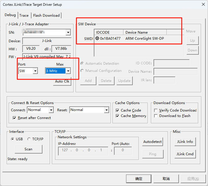
1. Due to the low isolation chip speed, the microcontroller recognition in SWD mode needs to be adjusted to 3MHz (for reference only):
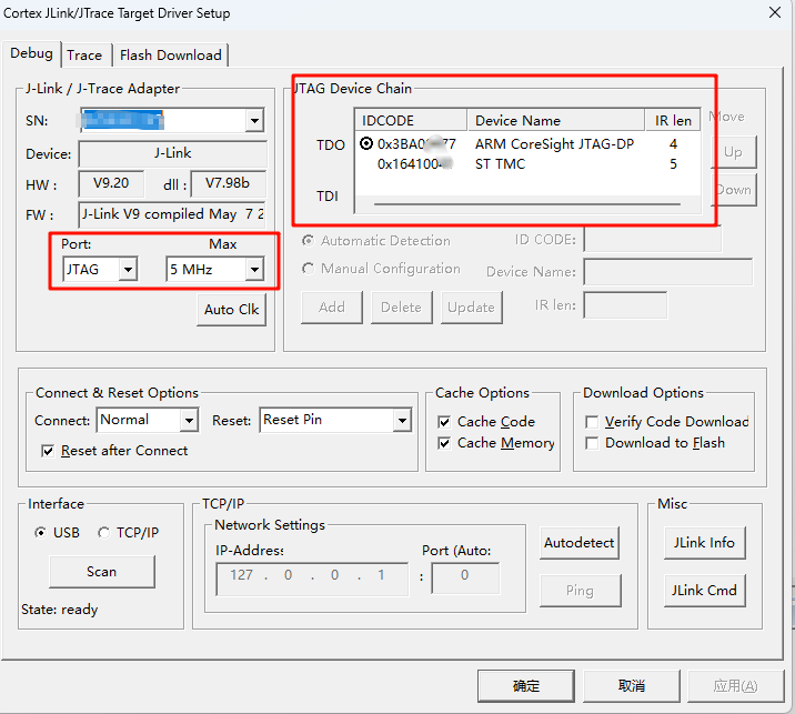
2. Using the D version of J-Link v9 in JTAG mode (for reference only):
Please note that if your code disables the JTAG pin, you cannot use JTAG mode to download normally. You need to switch to SWD mode or other modes and download the code that does not disable the JTAG function. Generally, JTAG is enabled by default.
Modifying the BOOT pins can also enable downloading.
3. Using the Zhengdian Atom DAP, a stable download speed of 5MHz can be achieved (for reference only):

Therefore, regarding the speed issue, you can modify the isolation chip or circuit scheme according to your own needs. This open source is for reference only.
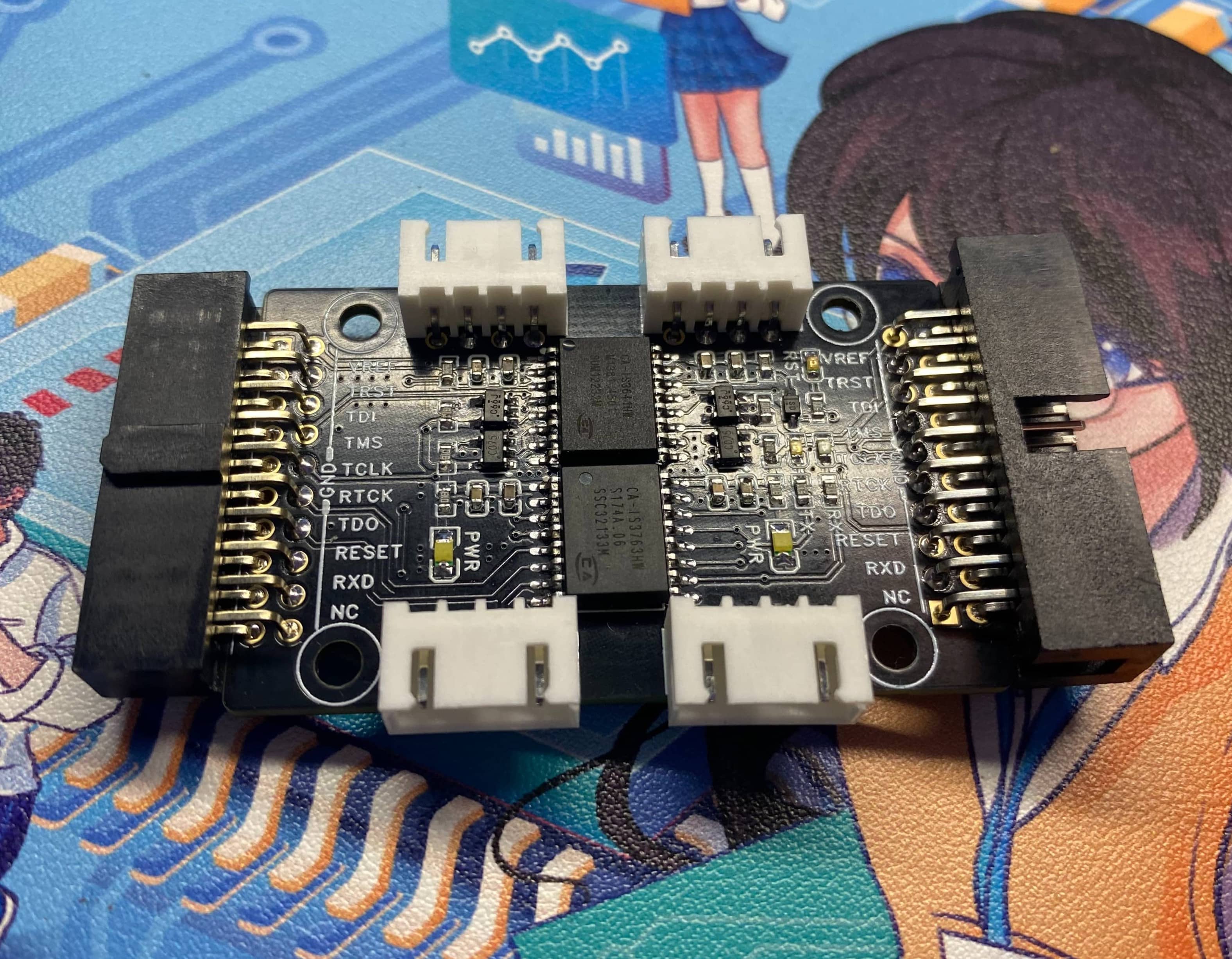
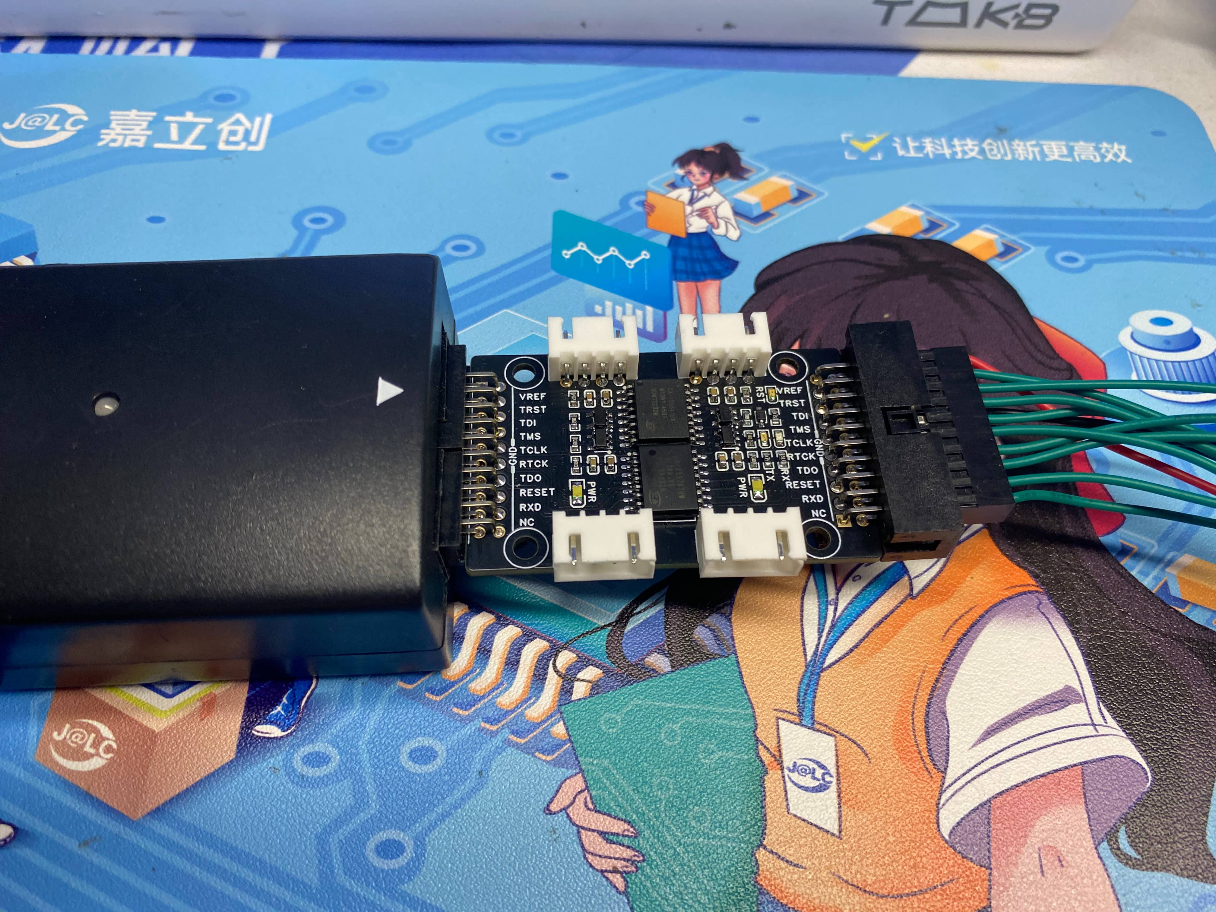
Physical Demonstration
Precautions
1. When soldering, please pay attention to the soldering order to ensure the power supply is correct and to avoid burning out subsequent circuits! The soldering order should follow the principle of from shortest to smallest, and from inside to outside.
2. The circuit has been verified. Solder according to the component parameters in the schematic diagram. It is recommended to prioritize soldering the main controller, which is more difficult to solder; a heated soldering station is recommended
. 3. When using board cleaning fluid, be careful not to touch the buttons, as corrosion will make them difficult to use.
4. It is recommended to use the schematic diagram parameters; the BOM table contains errors.
Acknowledgements
Thank you for your patience in reading. Given my limited technical level, if there are any omissions or errors, please provide valuable feedback.
This issue's open-source materials are analyzed and referenced in principle by the following experts (in no particular order):
1. Jlink-SWD Isolation
2. Isolation DAP-Link Debugger Based on AT32F415
3. JTAG High-Speed Isolation
4. [Four-Layer Board] STM32-Based DIY JLink_V9 ARM Emulator Version 2.0
5. Enabling VCOM (Virtual Serial Port) Functionality in Jlink v9
6. Jlink Official Driver Website
7. The Most Comprehensive Definition of JTAG and SWD Interfaces in History / A Boon for STM32/STM8 Engineers / JTAG to SWD Interface Simulation / Say Goodbye to Messy Emulation Cables / Finally, JTAG/SWD Explained Clearly


 京公网安备 11010802033920号

 1200CG1G502A3GB


