My initial motivation for creating
this was that my computer only had one Thunderbolt 4 port. Although I bought a Xiaomi 5-in-1 docking station (as shown in the picture)

, I still didn't have enough ports because I needed to connect too many USB devices. So, I had the idea of making my own hub splitter. Since I didn't have high speed requirements, I chose the SL2.1A hub chip, which supports USB 2.0. However, I felt that simply making a hub splitter and placing it on my desk would be too monotonous. Rather than investing in the production cost, I thought it would be better to just buy one. So, I wondered if I could expand the functionality of the hub. By chance, while browsing the LCSC open-source hardware platform, I saw the basic Dial project open-sourced by the developer morempty, which immediately attracted me. Since the SL2.1A supports one-to-four, I could use one of the ports to make a dial. I spent some time studying the basic dial, redesigning the board, and verifying it. Thus, this project came about. After obtaining permission from morempty, I open-sourced it. This is my first open-source project.
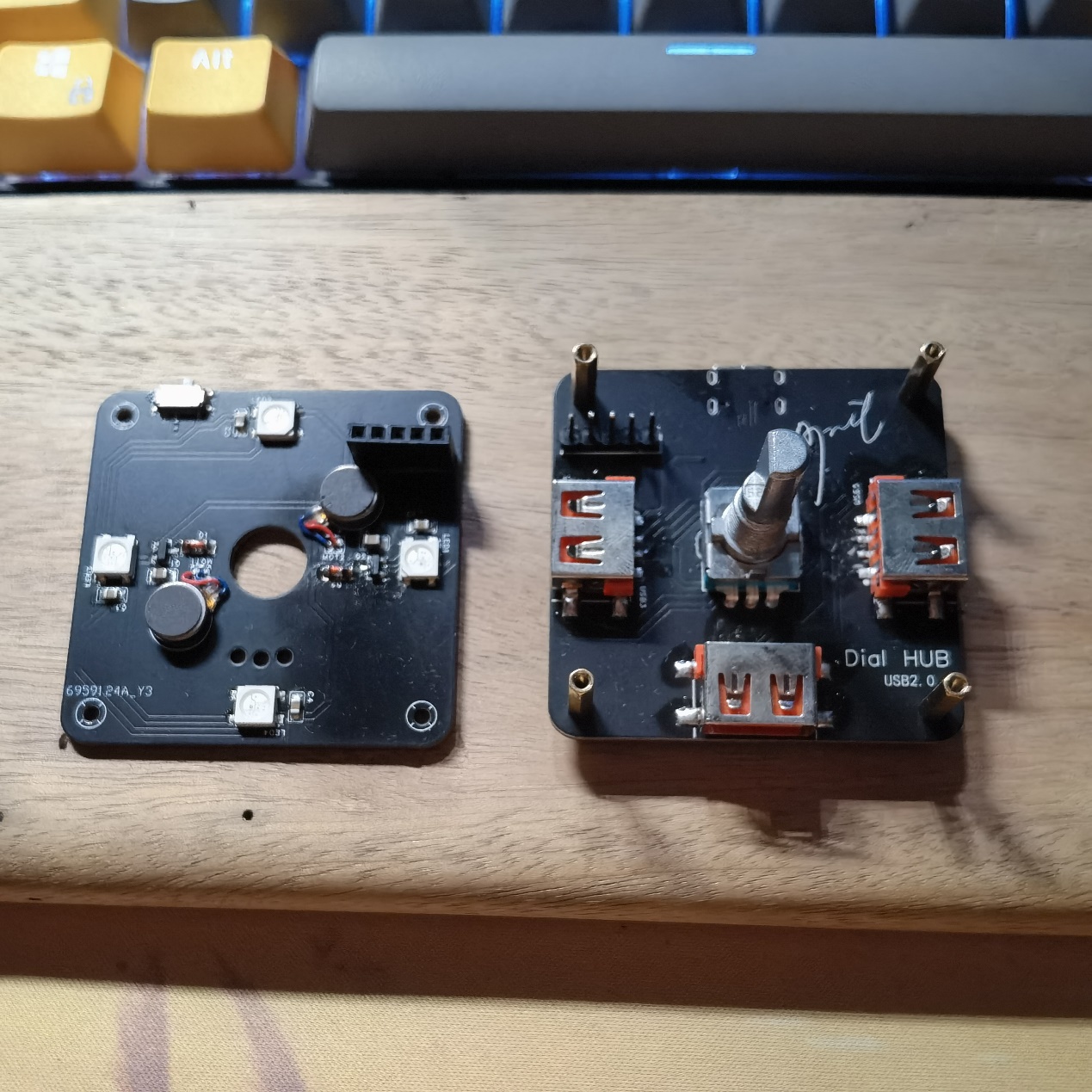
For the motherboard demonstration
, I first created a basic version without being sure if it would be successful, removing the RGB and vibration circuitry from the basic dial (as shown in the image).

Originally, this project would have ended after successful verification, but I encountered a problem—the part highlighted in red in the image. Initially, I planned to design a 3D-printed casing, so I extended the USB-A port slightly. This caused a problem: when soldering the SMD USB-A connector with a soldering iron, it was difficult to position correctly and easily soldered crookedly. Also, without RGB, the 3D-printed casing might not look good. Furthermore, the price of 3D printing is too high for an amateur electronics enthusiast like myself. Therefore, I created a second version, addressing all the aforementioned issues
. The current "Lighting and Vibration Extension" (now renamed "Pro") has optimized the wiring and component placement. Considering that some people may not like lighting and vibration, I have separated the lighting and vibration functions and placed them on the cover plate. They are connected to the motherboard via pin headers and sockets for easy installation and removal (as shown in the picture).
The four corners are fixed with M2*11+3 studs because the pin headers and sockets I purchased fit together exactly 11mm. If you do not plan to use lighting and vibration or use DuPont wires for connection, you can use M2*7~8 studs for fixing. Note that if you use M2*11 studs, it is recommended to purchase an EC11 encoder with a shank length of 20mm. If you use M2*7~8 studs, it is recommended to purchase an EC11 encoder with a shank length of 15mm.
Some points to note during assembly (soldering tools: heating table + soldering iron):
First, the header pins. Most header pins are too long for a 1.6mm PCB, so for flatness, trim them appropriately with pliers or nail clippers before soldering. Second, it's best to solder the header pins onto the cover plate, as the header pins are much harder to trim than the header pins.
Next, the soldering order is recommended: main components of the motherboard (excluding encoder, header pins, and USB-A interface) → components of the cover plate (including header pins) → USB-A interface on the motherboard → header pins and encoder (the header pins need the cover plate's header pins for positioning during soldering). Note that M2*11+3 studs are needed for fixing and positioning during the soldering of the header pins and encoder!
Do not solder 0Ω resistors with the symbol R4 at this time!
Knob Function Description (Default Firmware Version V1.32):
Morempty has described the knob functions in his project, with a fairly detailed description of the dial function. I won't go into too much detail here, but I will provide a link to the "Bare Dial" project later, where you can learn about the functions, flashing methods, and download the firmware. There is also a multimedia mode in the firmware that isn't described in detail, but here's a brief description:
In dial mode, a six-click rotation of the knob enters multimedia mode (you'll see the lights rotating counter-clockwise). Similarly, a six-click rotation in multimedia mode returns to dial mode (the lights rotate clockwise).
In multimedia mode, rotating the knob adjusts the volume, a single click pauses or plays a song, a double click skips to the next track, and a triple click skips to the previous track.
A five-click rotation in multimedia mode adjusts the brightness of the RGB lights or turns them off.
Some EC11 encoders may be reversed in dial mode; in this case, you can enter multimedia mode. In multimedia mode, an eight-click rotation changes the EC11's operating direction, and a six-click rotation returns to dial mode.
Special thanks
to morempty for the open-source hardware materials and 生菜 for the firmware resources.
Regarding third-party sellers (to paraphrase 生菜)
, I have a suggestion: the author hopes buyers will post reviews with pictures in this comment section.
If sellers become profitable enough, could they consider tipping the author to help with future development and improvements?
Of course, selling 5 sets or less is fine; from what I understand, most sellers are students, and I support them recouping some costs.
Perhaps for sales exceeding that, a 2 RMB tip for each set sold could be given to the author? (I would pass this on to 生菜 and morempty, I won't use it myself.) More than that is unnecessary; otherwise, the cost will be passed on to the buyer, reducing competitiveness.
Related Links
: Original Dial Project Link: [Spark Project] Dial - JLCPCB EDA Open Source Hardware Platform (oshwhub.com)
Regarding the BOM,
I feel that some components in the BOM exported by JLCPCB EDA are not accurate. Basically, buying according to the schematic I provided and my description above should not be a problem. There are only a few special ones, which I have listed below. Purchase according to your needs:
M2*4 screws
, M2*4 studs or M2*5 studs,
M2*11+3 studs,
straight-edge USB 2.0 connector, AF female (SMD four-pin full surface mount)
, 1A 8V surface mount, SMD self-resetting fuse,
all surface mount components are packaged in 0805,
vibration motor model is 0827,
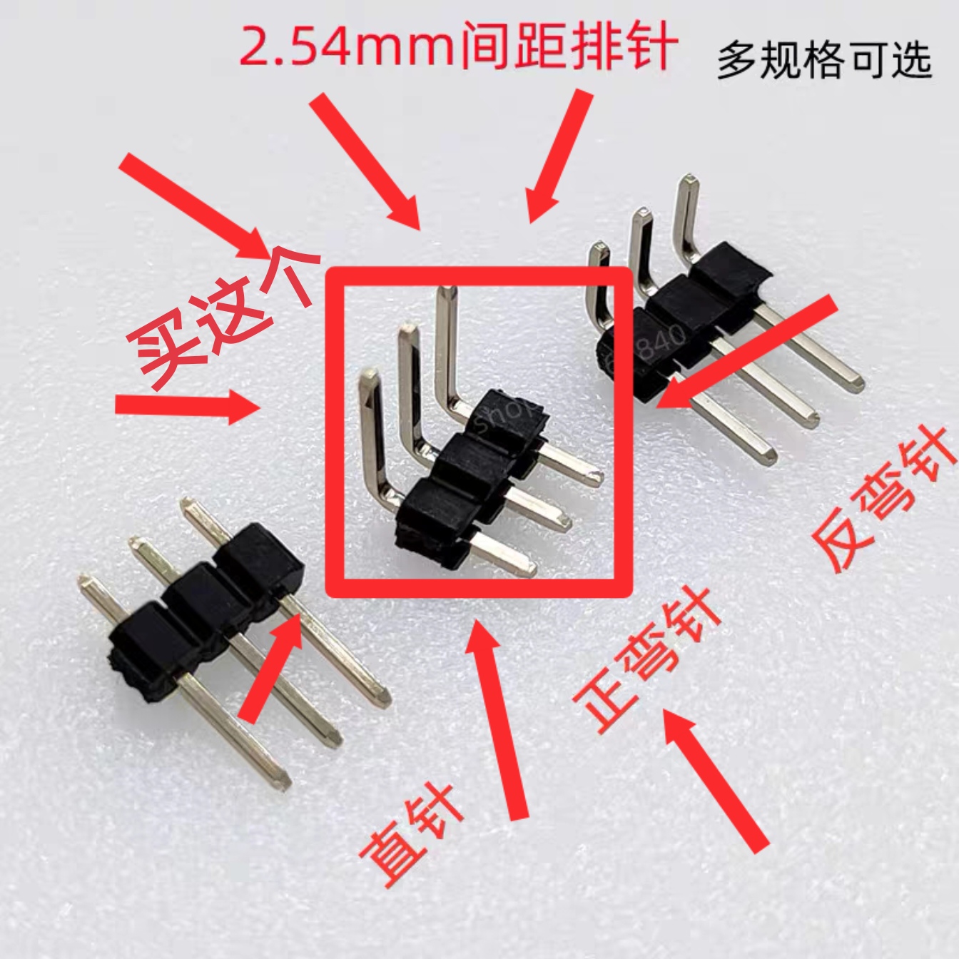
TTL version uses 7-pin positive bend single row header, as shown in the picture.
If you are still unclear, you can send me a private message to ask. If there are many people replicating and there is demand, I will rewrite the BOM.
Version Update
2023.10.20 Update:
Optimized some wiring details;
modified some project names;
added TF card reader version. (Unverified; feedback is welcome if anyone has verified it, and further optimization will be implemented in future versions.)
There were also plans to optimize the cover plate, but considering the difficulty and high cost of sourcing the necessary components, which would unnecessarily increase costs, this plan has been temporarily abandoned.
Update 2023.11.01:
Added a TTL serial port version, based on the CH340C design; (Unverified, feedback is welcome).
Uploaded the 3D model file (.step format) of the universal base, which can be ordered on JLCPCB's 3D Monkey platform. The model is shown in the image.

Uploaded the serial port version driver file; the default is the Windows version. For other versions, please download them from the official website. Driver link: Driver Program - Nanjing Qinheng Microelectronics Co., Ltd. (wch.cn)
V1.1 Version Finished Product Demonstration

and Operation Video.


 京公网安备 11010802033920号

 WJ1101CS53VDC.45


