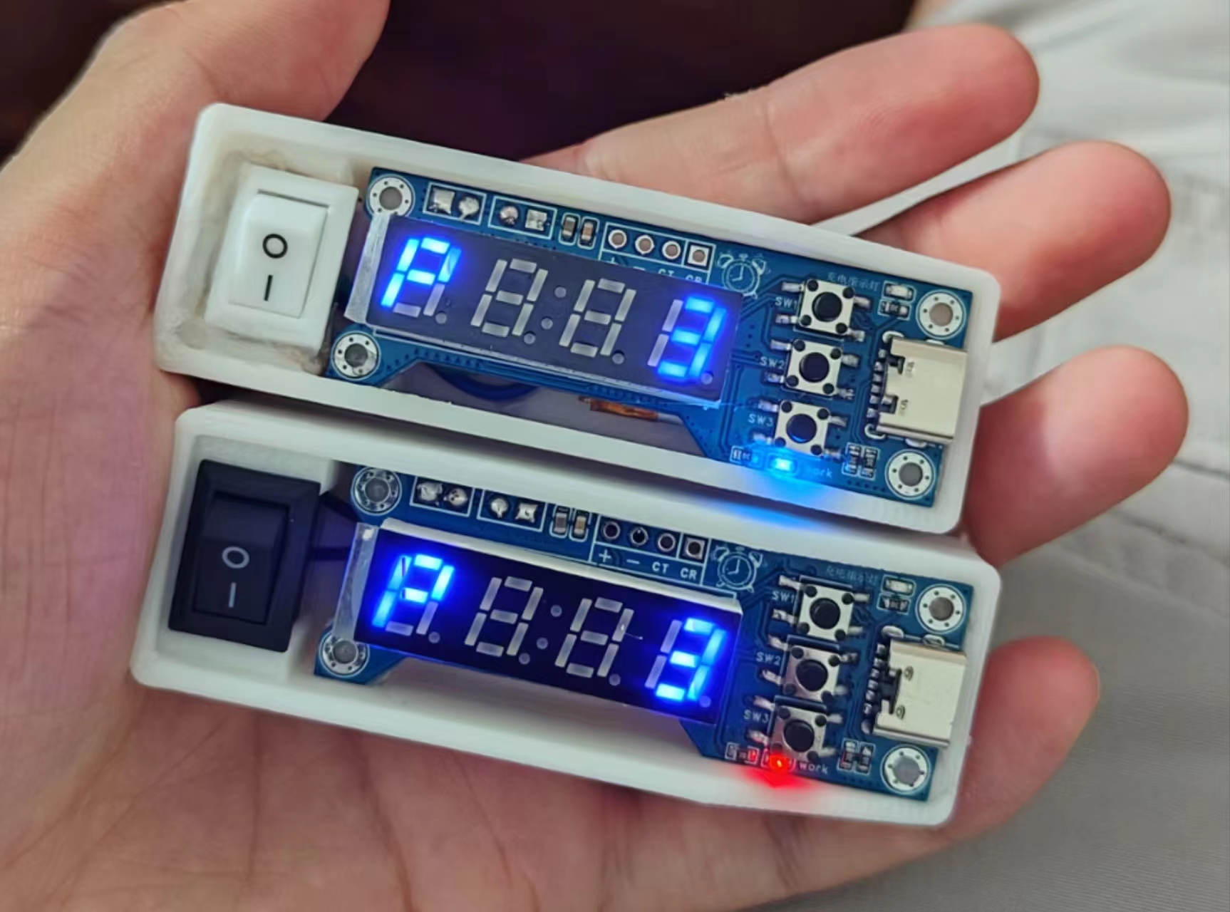
Essentially, it's a timer with a ramen noodle lid, hence the name "ramen noodle timer" (self-deprecating humor).
The device provides a countdown
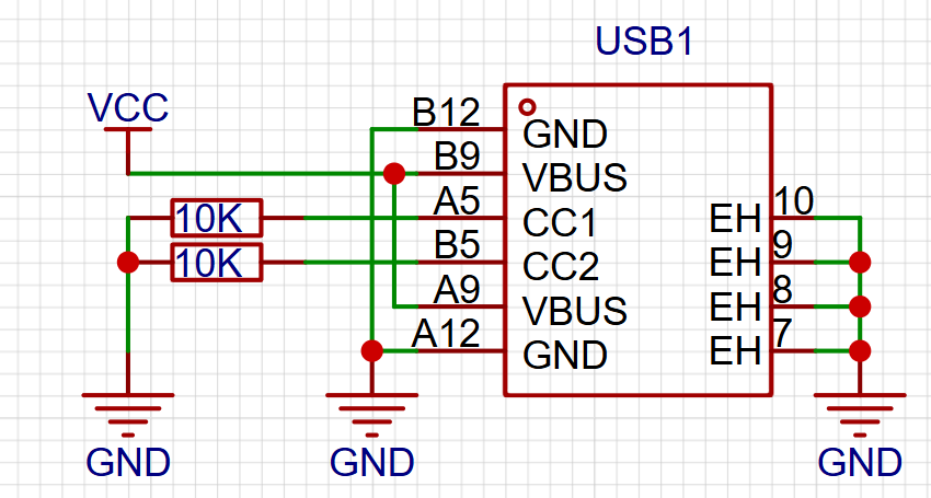
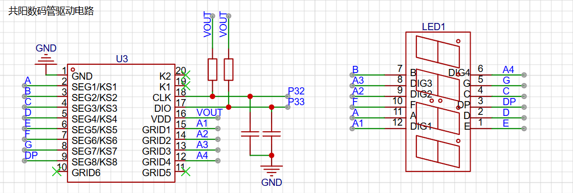
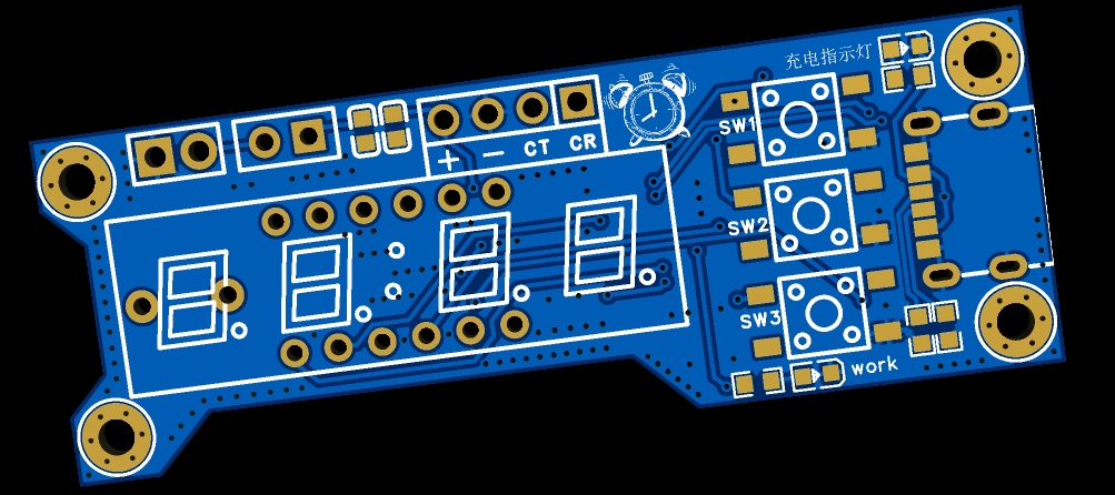
function, sounding an alarm when the time is up. It has a lithium battery and is portable. The device features a 120mAh lithium battery that can be charged via a Type-C port. Note that the CC1 and CC2 pins require external pull-down pins. The device uses a TP4054 chip for charge/discharge protection of the lithium battery. The display module uses a four-digit LED display and a TM1637 driver chip. It has three buttons for "increment/decrease" and "start/stop timing," located vertically on the right side of the LED display. Two status indicator lights are present: an external power input indicator that illuminates when there is external power input to the Type-C port, indicating that the battery is charging; and a VOUT output indicator controlled by an external switch. When the switch is closed, the device starts working; otherwise, it does not start. The VOUT status light illuminates when the device starts. Interface Description: The device PCB has three sets of interfaces, arranged horizontally above the digital tube. The image below shows the front and back of the PCB. The leftmost interface is the battery interface; connecting a lithium battery to this interface provides power to the device. Next to it is the external switch interface; connecting the switch to this interface enables power on/off switching. The rightmost interface is the programming interface, used for chip programming. This device uses the STC8G1K08A chip; please use a compatible serial programmer for programming. The program is developed using STC-ISP + Keil5 + VS Code. A hex file is provided in the attachment. tm1637.c / tm1637.h provide the digital tube display control function. main.c is the main program file. ST8HGH is the header file. #include "STC8G.H" #include "INTRINS.H" #include "tm1637.h" /** * Pin definitions */ sbit Buzz_IO = P5^4; // Buzzer /** * Variable definitions */ unsigned char mode_flag = 0; // Default is parameter setting mode unsigned char data_min = 3; // Timer value unsigned int back_time_s = 0; // Countdown value unsigned char isok = 0; // Countdown end flag /******************System Initialization**************** */ void System_Init(){ P5M0 |= 0x10; P5M1 &= ~0x10; // Buzz_IO set to push-pull output Buzz_IO = 0; P3M0 &= ~0x0c; P3M1 &= ~0x0c; P3M0 &= ~0x03; P3M1 &= ~0x03; P5M0 &= ~0x20; P5M1 &= ~0x20; } /******************System Initialization**************** */ /******************Button Monitoring**************** */ #define Button1 0 #define Button2 1 #define Button3 2 void ButtonClick(unsigned char button){ switch (button) { case Button1: // Increase if (mode_flag == 0) { data_min += 1; if(data_min > 99){ data_min = 99; } } break; case Button2: if (mode_flag == 0) { mode_flag = 1; // Enter countdown mode back_time_s = data_min * 60; }else{ mode_flag = 0; // Parameter mode back_time_s = 0; } break; case Button3: // Decrease if (mode_flag == 0) { data_min -= 1; if(data_min data_min = 1; } } break; default: break; } } void keyCheckLoop(){


P55 = P30 = P31 = 1; // Pull up the button
if(P55 == 0){
ButtonClick(Button3);
while(P55 == 0);
}
if(P30 == 0){
ButtonClick(Button1);
while(P30 == 0);
}
if(P31 == 0){
ButtonClick(Button2);
while(P31 == 0);
}
}
/******************Button Monitoring**************** */
/******************Countdown Module**************** */
void Delay300ms(void) //@11.0592MHz
{
unsigned char data i, j, k;
_nop_();
_nop_();
i = 13;
j = 156;
k = 83;
do
{
do
{
while (--k);
} while (--j);
} while (--i);
}
void stopCheck(){
unsigned char number = 0;
if (isok == 1) // Timing ends
{
for (number = 0; number
{
Buzz_IO = 1;
Delay300ms();
Delay300ms();
Buzz_IO = 0;
Delay300ms();
Delay300ms();
Buzz_IO = 1;
Delay300ms();
Delay300ms();
Buzz_IO = 0;
Delay300ms();
Delay300ms(); Buzz_IO =
1 ; Delay300ms(); Buzz_IO = 0 ; Delay300ms ( ) ; Delay300ms( ) ; Timer0_Isr(void) interrupt 1 { timer1_number++; if (timer1_number >= 20) // Triggered once per second { timer1_number = 0; if (mode_flag == 1) { back_time_s -= 1; if(back_time_s == 0){ isok = 1; } } } } void Timer0_Init(void) //50 milliseconds@12.000MHz { AUXR &= 0x7F; //Timer clock 12T mode TMOD &= 0xF0; //Set timer mode TL0 = 0xB0; //Set timer initial value TH0 = 0x3C; //Set timer initial value TF0 = 0; //Clear TF0 flag TR0 = 1; //Timer 0 starts timing ET0 = 1; //Enable timer 0 interrupt EA = 1; //Enable global interrupt
}
/******************Countdown Module**************** */
/******************Digital Tube Display**************** */
void SHUMA_DISPLAY(){ // Call this method to update the display interface
switch (mode_flag)
{
case 0: //Parameter setting interface
if (data_min
{
TM1637_Display(19,21,21,data_min);
}else{
TM1637_Display(19,21,data_min/10,data_min%10);
}
break;
case 1: //Countdown running interface
TM1637_DisplayInt(back_time_s);
break;
default:
break;
}
}
/******************Digital Tube Display**************** */
void main(){
System_Init();
Timer0_Init();
while(1){
SHUMA_DISPLAY(); //Interface display
keyCheckLoop(); //Key detection
stopCheck(); //End monitoring
} To program the serial programmer , you need some basic STC knowledge; programming itself shouldn't be a problem.
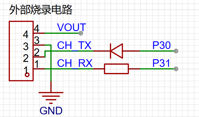
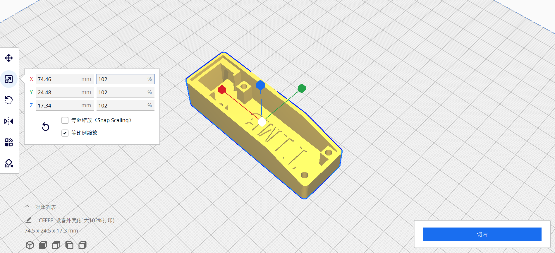
CH_TX / CH_RX represent the TX / RX pins of the serial programmer. Regarding the 3D casing: please expand the casing to 101% or 102% when printing.


 京公网安备 11010802033920号

 3PMT15A


