Note: Commercial use of this open-source product is prohibited. The source code still has some issues and will be uploaded later with a board update.
The weather API in the previous version is no longer working; a new firmware has been uploaded. Please use the new firmware. This version still has bugs and is currently developing new code using Arduino. Please wait!
I. Team Introduction:
II. Name:
III. Design Summary:
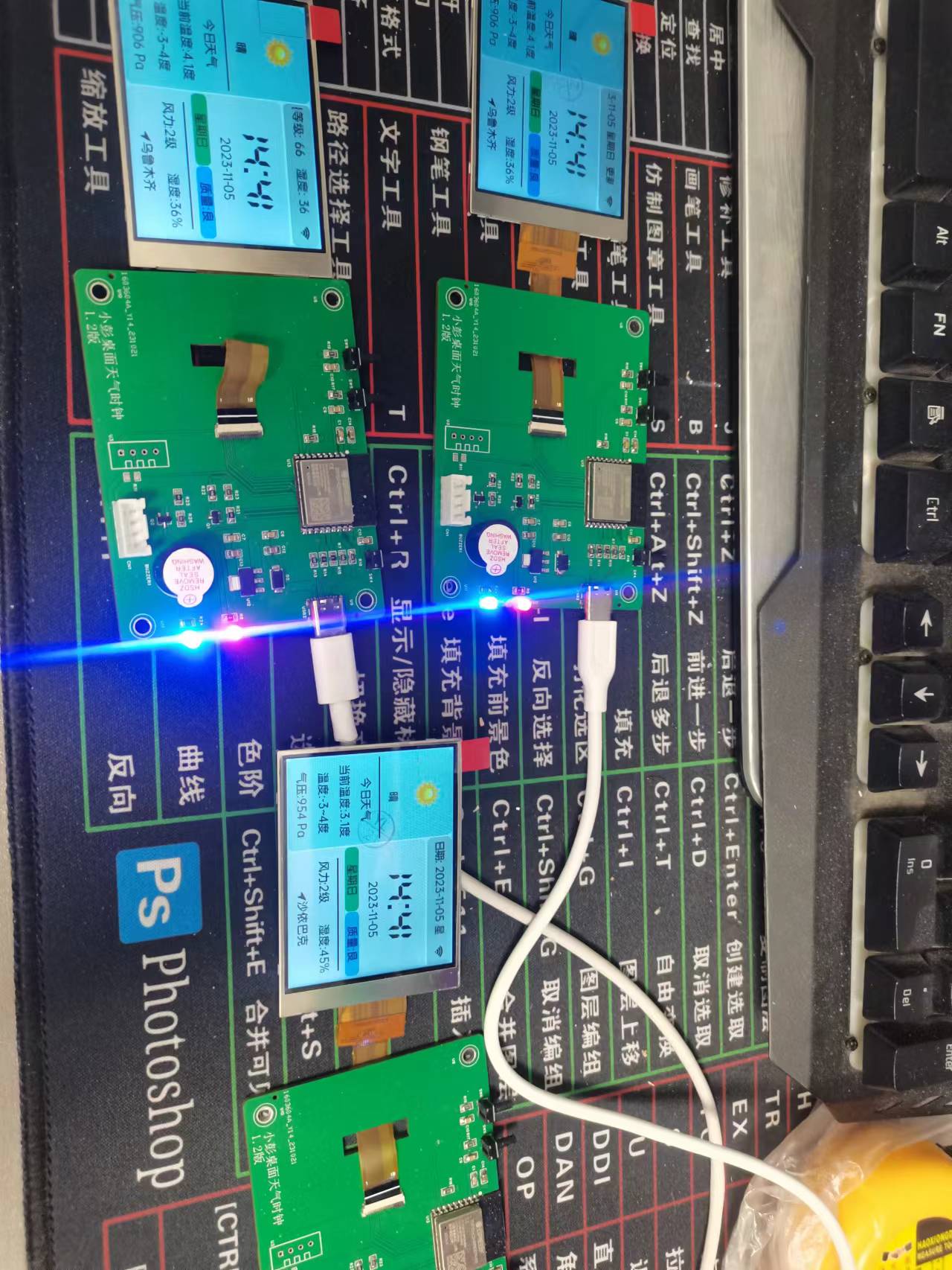
A desktop weather clock developed using the Espressif ESP32C3.
Main control chip: Espressif ESP32C3 4M.
Code voice: luatos from HeZhou.
1. Web network configuration: For first-time use, connect your phone to the XPZNIOT WiFi network. Enter 192.168.4.1 in your phone's browser to access the network configuration interface (blue light flashes before initial configuration, solid blue light after successful connection);
2. Real-time weather: Automatically restarts after network configuration (blue light flashes when acquiring weather data, solid blue light after successful acquisition), acquiring network time and real-time weather (current temperature, highest and lowest temperatures, air pressure, reminders, implementation time, day of the week, air quality, temperature, humidity, location, etc.);
3. Calendar function: Nothing much to explain;
4. Information function: Just some author information, nothing much to introduce;
5. Button function: Three buttons: page up, restart, and screen brightness.
6. Buzzer: Currently, only button clicks produce a sound.
7. LED Indicator: A solid red light indicates power-on; a flashing blue light indicates network connection or weather alert.
8. Future Functions: Alarm clock, sedentary reminder, work reminder, hourly time announcement, and simple voice control.
IV. Display Screen Connection
[Taobao] https://m.tb.cn/h.5BjuH1B9soo3rUL?tk=rErvWK4FErO CZ3458 "2.8-inch TFT LCD screen, IPS full-viewing angle SPI serial port screen, ST7789 capacitive screen, 18PIN" Click the link to open directly or search on Taobao.
V. Code and Shell Files
Import and download the code to the chip using HeZhou's Luatools (tutorials are available online if needed).
The shell is for reference only; you can modify the studs if necessary.
Specific details can be downloaded from the attachment.
VI. Image Display
The intelligent heated glove system is designed with the following main functional modules:
heating module, heart rate and blood oxygen monitoring module, posture detection module, lighting and warning light module, BLE wireless Bluetooth communication module,
main controller: STM32F103C8T6,
power supply module: equipped with a rechargeable lithium battery.

Intelligent Heated Gloves with Heart Rate Detection Function
Medical Instrument: Principles and Design Course Design Report
Bilibili Demonstration Video: https://www.bilibili.com/video/BV12vgYesESY/
2024
Table of Contents
I. Introduction 2
II. System Design Scheme 3
III. Hardware Design 4
3.1 Power Supply Module Design 4
3.1.1 TP4056 Chip 4 3.1.2
SX1308 Chip and ME6212C33M5G Chip 4
3.2 Main Control and Sensor Integration Board Design 6
3.2.1 MPU6050 Chip 6
3.2.2 MAX30102 Module 7
3.2.3 Overall Idea 8
3.2.4 Design Concept 8
3.3 Hardware System Block Diagram 9
IV. Software Design 9
4.1 Overall Software Design 9
4.2 Main Control Software Design 10
4.2.1 Instruction Acquisition and Parsing 10
4.2.2 Heart Rate and Blood Oxygen Measurement 11
4.2.3 MPU6050 Status Judgment 11
4.24 Constant Temperature Heating 12
4.25 Data Packaging and Transmission 13
4.26 Logic Diagram 15
4.3 Upper Computer Software Design 16
4.31 Introduction to Visual Interface 16
4.32 Receiving and Unpacking Data 16
4.33 Configuration and Sending Commands 18
4.34 Upper Computer Logic Diagram 19
V. Result Testing 19
5.1 LED Strip 19
5.2 Heart Rate and Blood Oxygen 20
5.3 MPU6050 21
5.4 Heating 21
VI. Appendix 21
I. Introduction
1.1 Background and Significance of the Topic
With the improvement of living standards, people's needs for personal protective equipment are becoming more diverse. However, in outdoor work and sports in low-temperature environments, traditional warm gloves often cannot meet users' dual needs for comfort and functionality. Intelligent heated gloves have become the best solution to this problem.
1.2 Current Development Status and Trends
Currently, intelligent heated gloves on the market usually adopt advanced electric heating technology, powered by a built-in battery, to achieve continuous heating of the hands. These gloves are typically equipped with intelligent control systems that can adjust the temperature according to the user's needs, ensuring that the hands are always kept within a suitable temperature range.
The development trend of intelligent heated gloves in recent years has mainly focused on improving heating efficiency, enhancing user experience, and expanding application scenarios. For example, some new heated gloves use air heating technology, where air pumped in by a micro-pump transfers heat through heat exchange, providing users with continuous and uniform heat. This technology not only improves heating efficiency but also helps protect users from the harm of extreme cold environments.
1.3 Practical Content
After reviewing various materials on intelligent gloves and conducting preliminary market research, we believe that intelligent gloves can be uniquely designed according to different user needs. We decided to design an intelligent heated glove for workers in cold environments. It should have a rechargeable module to continuously power the device for a period of time, and it should also have functions for monitoring the user's physical condition, as well as remote control of the device and display of the user's physical data.
1.4 Market Prospects
The application prospects of intelligent heated gloves are broad. In addition to traditional outdoor work and sports fields, it can also be extended to professional fields such as medical rehabilitation, military, and aerospace. For example, in the field of medical rehabilitation, intelligent heated gloves can be used to assist in the treatment of hand injuries or diseases, helping patients restore hand function. In the military field, smart heated gloves can provide soldiers with extra warmth and protection, improving their survivability. In the aerospace field, smart heated gloves can provide pilots with a more comfortable operating environment and reduce fatigue during flight.
In summary, smart heated gloves are not only a technologically innovative product but also a practical tool that meets the needs of modern society. Their development and popularization will bring many positive impacts. With the increasing demand from consumers for personalized and intelligent products, this type of product is expected to become a new consumer hotspot.
II. System Design Scheme
The smart heated glove system design includes the following main functional modules:
Heating Module: Employs constant temperature control technology to keep hands warm through built-in heating elements.
Heart Rate and Blood Oxygen Monitoring Module: Integrates a MAX30102 sensor to monitor heart rate and blood oxygen levels in real time.
Attitude Detection Module: Uses an MPU6050 sensor to monitor hand posture and movement.
Illumination and Warning Light Module: Integrates LED light strips on the glove for illumination and warning functions.
Wireless Bluetooth Communication Module: Enables communication between the glove and a host computer (such as a mobile phone) via a BLE Bluetooth module.
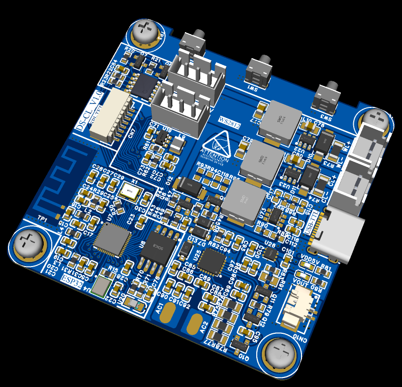
Power Supply Module: Equipped with a rechargeable lithium battery, supporting Type-C interface charging, using a TP4056 chip for charging management, an SX1308 chip for voltage boosting, and an ME6212C33M5G chip for voltage regulation.
The entire system is managed and coordinated by a main control board (STM32F103C8T6) to ensure the effective operation of each module and real-time data transmission.
III. Hardware Design
3.1 Power Supply Module Design
3.1.1 TP4056 Chip The
TP4056 is a linear charger chip specifically designed for single-cell lithium-ion batteries. It uses a constant current/constant voltage charging method and can provide a programmable charging current of up to 1000mA.
When the chip power supply voltage is less than 3.6V, the chip is in shutdown mode, and both LEDs are off. When the power supply voltage is greater than 3.6V and the battery voltage is less than 2.9V, the chip is in pre-charge mode, with a charging current of one-tenth of the set current. When the battery voltage exceeds 2.9V, it enters constant current charging mode, with the charging current set through the resistor on the PROG pin. When the battery voltage reaches 4.2V, it enters constant voltage charging mode, maintaining the charging voltage at 4.2V. When the charging current drops to one-tenth of the set current, the charging cycle ends, the charging completion indicator lights up, and the charging indicator turns off. If the battery voltage drops below 4.1V, the chip will re-enter constant current mode to continue charging.
3.1.2 SX1308 Chip and ME6212C33M5G Chip The
SX1308 is a fixed-frequency current-mode boost converter in an SOT23-6 package, operating at frequencies up to 1.2MHz, allowing for the selection of smaller external inductors and capacitors. The chip features a built-in soft-start function to reduce inrush current during startup. Under light loads, the SX1308 automatically switches to Pulse Frequency Modulation (PFM) mode to reduce power consumption. Furthermore, the SX1308 includes input undervoltage lockout, current limiting, and overheat protection features, contributing to improved system stability and safety.
The other chip, ME6212C33M5G, is mainly used in electronic devices requiring a stable 3.3V output voltage.
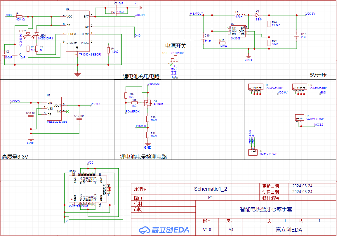
[Power supply protection module schematic diagram,
circuit board schematic diagram,

power supply protection module physical image]
3.2 Main Control and Sensor Integration Board Design
3.2.1 MPU6050 Chip The
MPU6050 is a sensor integrating a 3-axis gyroscope and a 3-axis accelerometer, providing detailed data on the device's motion status. It helps users understand the device's motion by measuring the angular velocity and acceleration along three spatial axes (X, Y, and Z axes). The gyroscope section measures angular velocity by detecting the Coriolis force caused by rotation. The accelerometer section measures the acceleration along each axis during the device's acceleration process.
This chip internally has a 7-channel 16-bit ADC conversion circuit, including 3 channels for the gyroscope, 3 channels for the accelerometer, and 1 channel for an internal temperature sensor. The data converted by the ADC is processed by a digital motion processor (DMP) and then stored in a FIFO. The microcontroller controls the MPU6050 by reading and writing to its internal registers. We primarily use it to acquire the instantaneous three-axis acceleration of the glove. By setting a certain safety threshold, if the acquired acceleration exceeds the threshold, it indicates that the user is in a rapid movement, potentially posing a fall or other risk, and a warning should be issued.

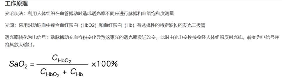
3.2.2 MAX30102 Module The
MAX30102 is an integrated pulse oximeter and heart rate monitor biosensor module manufactured by Analog Devices. It includes multiple LEDs, photodetectors, optical devices, and low-noise electronic circuitry with ambient light suppression. Commonly used in wearable health devices, it provides highly sensitive pulse oximetry and heart rate monitoring.
Its working principle is based on the absorption spectrum characteristics of hemoglobin. It uses red and infrared LEDs to illuminate the skin and collects the reflected light signals through a photodetector. By analyzing the difference in absorption of red and infrared light by oxyhemoglobin (HbO2) and hemoglobin (Hb), blood oxygen saturation can be calculated. Simultaneously, the heart rate can be calculated through the periodic changes in the reflected light signal.
3.2.3 Overall Design The main
control uses an STM32F103C8T6 chip, equipped with an MPU6050 accelerometer chip, integrating a MAX30102 module, a BLE wireless Bluetooth module, and two DS18B20 temperature sensors. This glove can measure heart rate, determine simple postures, acquire temperature, communicate with a host computer, and control peripheral devices.
3.2.4 Design Concept
Low temperatures significantly affect the human body's heart rate and blood oxygen levels. In low-temperature environments, the human body constricts peripheral blood vessels to maintain body temperature, increasing the burden on the heart's pumping action, which can easily lead to increased blood pressure and increased venous return. These changes pose a severe challenge for patients with cardiovascular diseases. Low temperatures can also cause sympathetic nerve excitation, increasing heart rate, blood pressure, systemic vasoconstriction, increased peripheral resistance, increased myocardial oxygen consumption, and a greater likelihood of thrombus formation causing acute vascular obstruction, thereby increasing the risk of acute myocardial infarction. Monitoring heart rate and blood oxygen in cold weather is crucial for preventing cardiovascular disease and maintaining health. These measurements can be conveniently performed using professional medical equipment or smart wearable devices, allowing for timely and necessary health management measures.
Furthermore, cold weather can make roads slippery, increasing the risk of slips and falls for outdoor workers, potentially leading to injuries including fractures and fainting.
Wearing our gloves ensures that nerve endings remain warm, allowing for normal work even in cold weather. Users can check their heart rate and blood oxygen levels on their phones when feeling unwell for preventative purposes, and the flashing indicator light in case of an accidental fall attracts attention and facilitates timely assistance.
3.3 Hardware System Diagram

IV. Software Design
4.1 Overall Software Design
First, the host computer sends commands to activate the corresponding functions of the device. The main control board drives and reads the values of each sensor according to the commands, and the control board activates high-power peripherals. Simultaneously, a timer sends data packets. The host computer then unpacks the data packets to display the various data.
4.2 Main Control Software Design
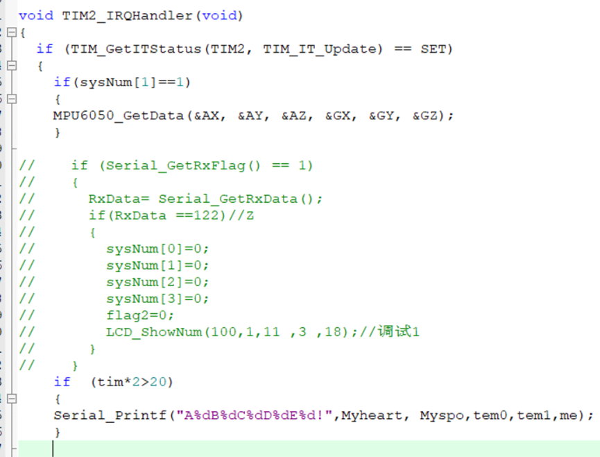
4.21 Instruction Acquisition and Parsing
The received characters are converted into decimal numbers using the corresponding array, and a four-digit status code is obtained through a bit separation function.

4.22 Heart Rate and Blood Oxygen Measurement
Codes are too numerous to show here.
4.23 MPU6050 Status Judgment
Data from the MPU6050 module, including three-axis acceleration and three-axis gyroscope values, is read via IIC communication. Data processing yields the results.
The absolute values of the three-axis acceleration and three-axis angular velocity are taken separately and then summed to obtain two total values. Judgment is made based on the magnitude and change of the total values, which can solve the interference caused by different initial acceleration values due to different initial positions of the gloves on the body.

4.24 Constant Temperature Heating
and Flipping I/O Two heating elements are controlled by two temperature sensors to achieve temperature control. (Due to power output limitations, only one heating element can operate at a time to ensure overall stability). Heating is performed in a short-duration, multiple-times mode.

4.25 Data Packaging and Transmission
Target data is packaged and transmitted periodically using a timer.

4.3 Host Computer Software Design
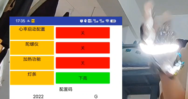
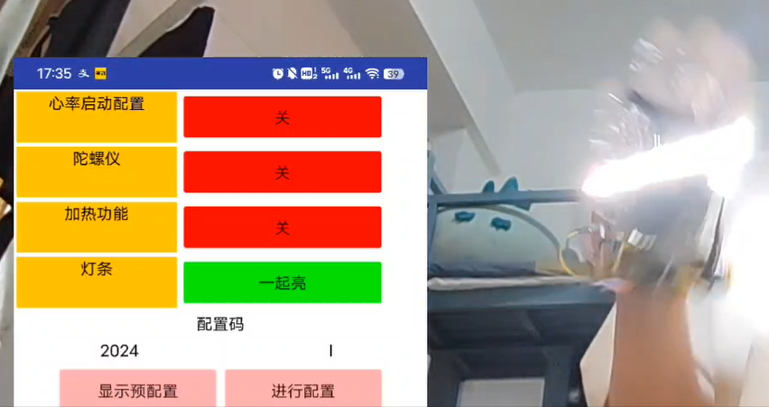
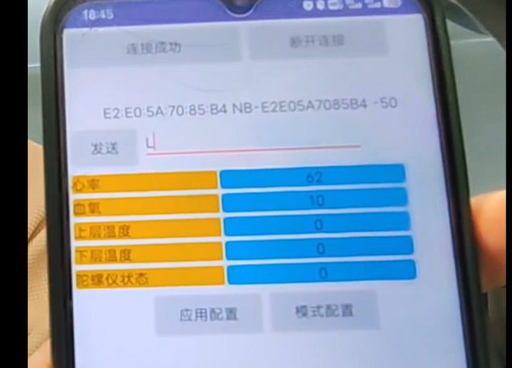
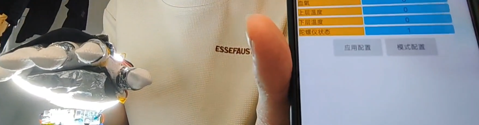
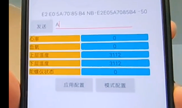
4.31 Introduction to the Visual Interface

4.32 Receiving and Unpacking Data:

Different data are separated by different letters, so identifying the corresponding letter allows unpacking the corresponding data.
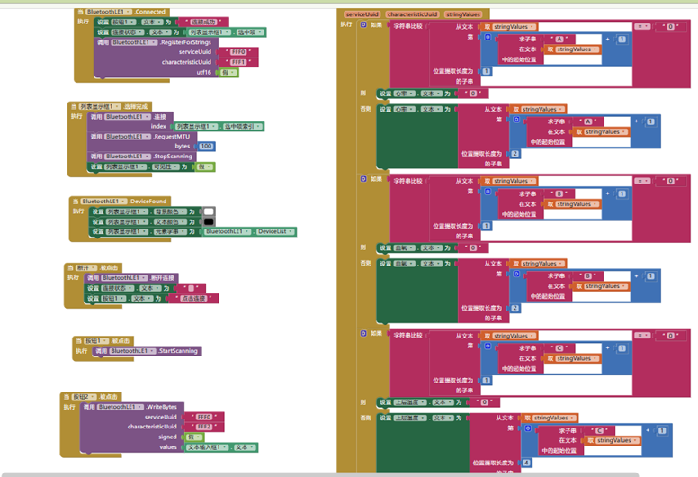
4.33 Configuration and Command Sending:
First, establish a Bluetooth connection, then configure feature quantities, combining the feature quantities into a four-digit number. Find the letter represented by this four-digit number and send that letter.

4.34 Host Computer Logic Diagram

V. Result Testing
5.1 LED Strip
5.2 Heart Rate and Blood Oxygen
Detection: Error-free, accuracy is generally accurate. However, because it is a wrist measurement, the error will be larger compared to finger measurement due to sensor limitations. (Blood oxygen is a minor bug; a three-digit number will display as a two-digit number, when it is actually 100).
5.3 MPU6050
successfully detected the hand-turning motion.
5.4 Heating
Temperature Display: Normal, and the temperature rises slowly.
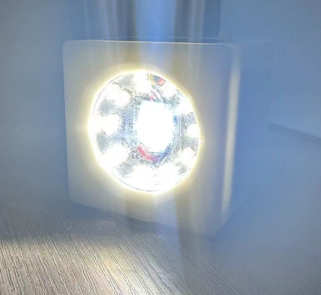
This is a multi-functional LED fill light. The LED light board features one WS2812 RGB color LED with 16 LED beads, offering adjustable color for different scenarios; one warm light LED with a 10-series-2-parallel configuration; and one cool light LED with 38V COB beads.
I. Product Introduction This is a multi-functional LED fill light. The LED light board features one WS2812 RGB color LED with 16 LED beads, allowing for color adjustment for different scenarios; one warm light LED with a 10-series-2-parallel configuration; and one cool light LED with 38V COB beads. The control board has two boost LED current drivers and three buttons for switching light modes and adjusting LED height.
II. Board Functions 1. Powered by a single 3.7V 1000mA lithium battery. 2. Two WS2812 LED bead interfaces for RGB color illumination, with adjustable color and brightness. 3. One warm light LED dimming driver for warm light fill light and general illumination, using a 10-series-2-parallel configuration, estimated at 40V, 200mA. 4. One cold-light LED dimming driver for cold-light supplementary lighting and general illumination, using a single COB LED, 38V, 200mA. 5. Features a push-button switch for mode switching, UP and DOWN buttons for brightness adjustment. 6. The board is designed for a 5W receiving circuit, enabling wireless charging of the lithium battery. Currently, the project uses a Type-C wired charging method. 7.
The main control board of the board uses an ESP32 chip for control, and can be expanded to support WLED control mode.
III. Effect diagram of LED board + control board:
1. 3D view and physical image of the front of the LED board PCB (Note that my circuit uses 40V COB LEDs, which is the one used in the physical product. Single LEDs cannot be used in this project; the control circuit needs to be changed to a single LED step-down driver).

2. 3D view and physical image of the LED control board PCB .
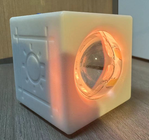
4. 3D photo of the casing (casing size is 65mm*65mm*65mm) .
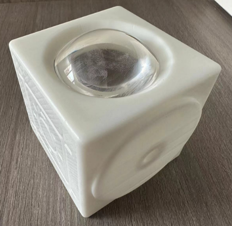
4. Physical photo


. IV. Circuit description and usage introduction: 1. This project consists of an LED board + LED control board. The LED board is made of aluminum substrate for easy heat dissipation of the LEDs. The board has 16 5050 WS2812 LEDs; one 40V, 200mA COB LED for cool light; and 10 series 2 parallel warm white 2835 LEDs, totaling 20.
2. Two WS2812 interfaces, using XH2.5 connectors. These are directly plugged into the control board. Currently, only one channel is needed on the LED light board, with 16 LEDs. This allows for different colors, brightness levels, or ambient lighting effects.

3. The project uses the SY7301 chip for both warm and cool light. This chip is an LED current driver chip. The SY7301A features a boost DC/DC converter to provide precise, constant current to drive the LEDs. Operating at a fixed switching frequency of 1MHz, it allows the use of small-value external ceramic capacitors and inductors. The series-connected LEDs are driven by a regulated current set by an external resistor. The SY7301A is ideal for driving up to 10 white LEDs in series or up to 40V.
Therefore, two channels are provided for warm and cool light control circuits, enabling switching between warm and cool light and brightness adjustment.

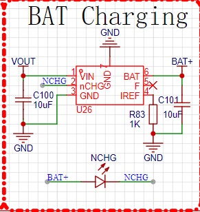
4. Single-cell lithium battery power supply, using SGM40560 charging IC, battery capacity is 1000mA, currently using Type-C charging (the circuit also reserves a wireless charging RX solution, which can be changed to wireless charging in later versions). A
SY7069 single-cell lithium battery boost IC is used to power the WS2812, providing power for both cool and warm light.
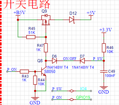
5. The board's switch circuit: when the switch is pressed, IO4 detects the button action. Hardware-wise, the p-MOS conducts, and after the MCU powers on, it pulls IO19 high, forming a self-locking mechanism.
6. 3D shell design: (The shape includes a lens, specifications are as follows.)
7. The lamp's top cover uses an acrylic cover plate, also printed by JLCPCB. Below are the acrylic printing specifications. Additionally, the PCB project file also contains the printed pattern, all open-source on the project platform. (The right side shows a color screen to be added later, a requirement for upgrades; updates are available. The color screen will display color, battery level, etc.)
V. Product test video.
 V. Code and Shell Files
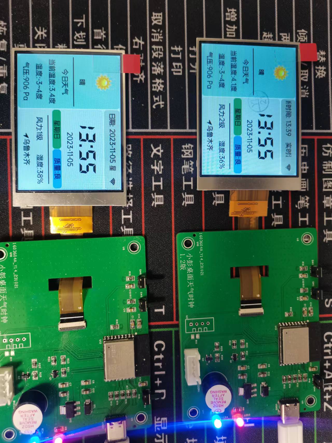
 [Power supply protection module schematic diagram,
  3.2.2 MAX30102 Module The
  IV. Software Design


 京公网安备 11010802033920号

 MI-QC6TW-MUY


